Hitting the spot
As optical components find their way into increasingly complex setups, designers and researchers are faced not only with the need to know more about optical theory, but also with the need to know more about the practice of optical positioning. Because optical positioners are used to facilitate the alignment of the optical components in a system, it follows that choosing the right parts will have a significant impact on both system price and performance.
The key to selecting the appropriate optical positioning components is to determine the performance that is required, the number of positioners that are needed, and the types of positioners that are available.
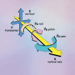
Figure 1: A three-dimensional system has six degrees of freedomthree linear and three angular.
A good place to start is to determine the number of degrees of freedom required to align the system. A degree of freedom is a unique movement used to position a three-dimensional object. For each dimension in 3-D space there is one linear and one angular degree of freedomsix degrees of freedom total. In Cartesian coordinates, the linear motions are usually referred to as x, y, and z, and the angular motions are typically θx , θy , and θz (see figure 1). These angular motions also are referred to as roll, pitch, and yaw respectively.
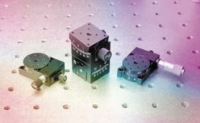
Figure 2: Rotation stages or goniometers introduce pure angular adjustment. (Melles Griot)
A positioner is designed to provide adjustment in one or more degrees of freedom. Translation stages provide linear motion for applications such as focusing and centering; tilt stages provide angular motion for applications such as optical-axis orientation; height-adjustable stages provide linear vertical adjustment; and goniometers and rotary stages provide pure angular adjustment (see figure 2). In many cases, several stages, each providing a single degree of freedom are stacked to provide multiple motions.
alignmentThe three most common alignment problems are aligning an axis to a fixed point (e.g., a laser to a detector), aligning a point to a fixed axis (e.g., a ball lens to a laser), and aligning two axes with respect to each other (e.g., a collimator to a laser). For each of these configurations, there is a minimum number and type of positioners needed to facilitate the alignment.
Aligning an axis to a fixed point: A minimum of two linear adjustments or two angular adjustments is required. For the special case in which the angular adjustment rotates about the axis of linear translation, one linear adjustment and one angular adjustment can be used.
Aligning a point to a fixed axis: This problem requires at least two linear adjustments. Although it would seem that aligning a point to a fixed axis would require the same number and type of positioners as would aligning an axis to a fixed point, this is not the case since angular adjustments are meaningless to a nondimensional object such as a point. For maximum precision, the two linear adjustments should be orthogonal to each other and to the fixed axis.
Aligning two axes: This problem requires at least two linear adjustments and two angular adjustments. This is the most difficult alignment operation because adjusting the angle of an axis will simultaneously produce an unwanted translation effect. The process for aligning two axes requires, first, that the axes be made parallel to each other using the angular adjustments and then collinear using the translation adjustments. If focusing is required in conjunction with an axis-to-axis alignment, a third linear adjustment must be added to the system. This focus positioner, a translation stage, should be oriented parallel to the optical axis.
The preceding examples indicate the minimum number and type of adjustments needed to align a specific type of system. Many cases, however, require additional positioners, particularly when a single positioner cannot meet all of the performance requirements of a specific degree of freedom. For example, if focusing a lens requires both long-range and high-resolution adjustments on the same axis, it is difficult to find a single translation stage that can meet both requirements. Long-range positioners typically have relatively poor resolution, and high-resolution positioners typically operate only over a short range. Consequently, the best solution is to use two separate positioners: one for coarse (long-range) adjustment and another for fine (high-resolution) adjustment.
resolving positionFrom the previous example, it is easy to see how the performance of an optical positioner can affect the selection of positioning components in an optical system. It is therefore necessary to have an understanding of the most common performance parameters associated with optical positioners: range, load capacity, resolution, and error.
Although the meaning of range and load capacity are self-evident, the meaning of resolution and error need clarification. Resolution is defined as the smallest move that can be made by a positioner. For manual positioners, resolution is heavily dependent upon the skill of the operator. Some people with extreme manual dexterity may be able to operate a positioner with significantly more resolution than others. Since most positioners are adjusted by rotating an actuator like a micrometer or a thumbscrew, the only way to make resolution in manual positioners non-user-dependent is to establish a reasonable minimum rotation on the actuators. To specify resolution, most manufacturers of manual positioning components assume a minimum actuator rotation somewhere between 1° and 5°.
For automated positioners like those incorporating stepping motors, the resolution is defined mechanically by motor-step size. In this case, each movement of a positioner is an integer multiple N of the resolution. This means that a positioner with a resolution of 5 µm, for example, can only locate an object N X 5 µm away from its starting point5 µm, 10 µm, 15 µm, 20 µm, etc. The more important implication is that this positioner cannot move an object to a location other than an integer multiple of 5 µm away from its current position. Thus a move to a position 8 or 43 µm away, for example, would be impossible for this component. Clearly, the components selected for a system must have resolution to match or exceed the system requirements.
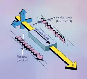
Figure 3: For linear motion, error terms are quantified as straightness of travel and flatness.
Like resolution, error is a measurement that reveals the performance limitations of a positioner. The most useful and frequently encountered error terms are straightness of travel, angular deviation, wobble, and eccentricity. Straightness of travel for a linear one-axis positioner is a measurement of nonintended linear movement along the other two linear axes. For example, 2.5 cm of intended linear travel along the x-axis might yield 10 µm of unintended linear travel along the y-and z-axes (see figure 3). Straightness of travel for the positioner, therefore, would be reported at 10 µm.
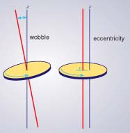
Figure 4: For rotational motion, the error terms are quantified as wobble and eccentricity.
For a rotary stage, the straightness of travel equivalent is a term called eccentricity. Eccentricity is a linear displacement of the mechanical center of the stage from the axis of rotation and is sometimes called runout (see figure 4).
Angular deviation is a counterpart to straightness of travel in that it is a measure of unintended angular changes over the travel range of the linear positioner. Angular deviation covers all three of the angular degrees of freedom: pitch, yaw, and roll. For an angular positioner like a rotary stage, the applicable error measurement is wobble. Wobble is the unintentional tilting of the axis about which the positioner is rotating. This error manifests itself as an angular and linear movement in the component being positioned.
It is important to note that all angular errors have the potential to create linear errors above and beyond those contributed by straightness of travel. The name for this phenomenon is Abbe error, and it is defined as a linear deviation combined with a lever arm. The longer the lever arm, the larger the Abbe error and vice versa. It is therefore good practice to keep this lever arm as short as possible by keeping the stage and component in close proximity.
There are many factors to consider in selecting the best optical positioner for an application. Although it can appear complex at first, taking a close look at the characteristics of the optical system being designed and matching those characteristics to the performance level of available positioners can eliminate many of the variables, resulting in a successful implementation. oe
Rick Sebastian is product manager of optical mechanical hardware at Melles Griot, Inc., Irvine, CA.