|
EG&G Photon Counter
Single Photon Counting Modules (SPCM)
The SPCM-AQ-1XY utilizes a unique silicon avalanche photodiode which has a circular active area. The peak photon detection efficiency over a 180 µm diameter exceeds 70% at 700 nm. If a larger detection area is required, the SPCM-AQ-2XY has a peak photon detection efficiency over a 475 µm diameter that exceeds 35% at 630 nm. The photodiode is both thermoelectrically cooled and temperature controlled, ensuring stable performance despite changes in the ambient temperature. The SPCM-AQ-1XY module utilizes a patented "active quench" circuit which can count to speeds exceeding 10 million counts per second. The SPCM-AQ-2XY can achieve 7 million counts per second. There is a "dead time" of 30 ns between pulses and single photon arrival can be measured with an accuracy of 300 ps FWHM. The SPCM-AQ require a +5 volt power supply (a mating cable is supplied with each module). A TTL pulse, 2 Volts high in a 50 W load and 9 ns (SPCM-AQ-1XY) or 40 ns (SPCM-AQ-2XY) wide is output at the rear BNC connector as each photon is detected. To avoid a degradation of the module linearity and stability, the case temperature should be kept between 10ºC and 35ºC during operation. Applications include: LIDAR, Photon Correlation Spectroscopy, Astronomical Observations, Optical Range Finding, Adaptive Optics and Ultra Sensitive Fluorescence.
Notes: 1) Absolute maximum ratings: 2) Connection to incorrect voltage or reverse voltage may destroy the module. The warranty is invalid where such damage occurs. 3) These modules are not qualified for shock or vibration other than normal instrumentation environments. 4) The module dissipates a mean power of 3.5W, and a maximum power of 8W at high count rates and 35ºC. Adequate heatsinking must be provided by clamping the module to a suitable heatsink via the ¼"-20 blind nuts in the module base. For the specified performance, the module case temperature must not exceed 35ºC. 5) Bistability of the dark count. On a small percentage of delivered modules, bistability of the dark count has been observed. Research indicates that this bistability is probably due to transitions at a single impurity site between a lower energy and a high energy state. The phenomenon is seen as an abrupt change in the dark count rate, e.g. 350 to 390 c/s, and the dark count switches between the two states at a rate which depends on the detector temperature. Multilevel switching has also been observed, where more than one impurity site is switching. Also, the SPCM-151 and the SPCM-161 have a maximum count rate of 5Mc/s. 6) EG&G performs a 6 hour screen on temperature stability which includes dark count; this test also screens for bistability and multistability. Longer term bistability would not be detected by this test because the phenomenon is related to fundamental semiconductor physics and is outside EG&G's control. Warranty claims will only be entertained if the high level of the dark count exceeds the "max" level in the specification. 7) In the dark, the module generates random counts that follow a "Poission" distribution. In a Poissonnian process the standard deviation (s) is equal to the square root of the average counts. In this specification the "dark count variation" refers to the stability of the average count of the module. 8) The actual photon rate could be calculated using the following equation: ACF = [(OMCR x CF) - DC]/PDE The theorical value of the Correction Factor follows this equation: CF = 1/[1-(tD x CR) The deviation from an ideal linear system is another way of looking at the saturation effect. The following equations show how to calculate this departure from the linearity: Linearity = [OMCR/(PhotonsActual Count Rate x PDE) + DC] - 1 = (1/CF) - 1
Fiber Connector Option - Ordering Guide 1 The SPCM-AQ-WXY-FZ has an "FC" fiber optic receptacle prealigned to the optical detector. Optical fibers with an FC connector on one end are available separately (See Ordering Guide 2). The photon detection efficiency of connectorized modules is about 90% of that quoted for standard modules. Fiber Shielding - When used with optical fibers, both the fiber itself and the connector shrouds must be completely opaque; if not, stray light will increase the count rate. The SPCM-QCX pigtails conform to the requirement (See Ordering Guide 2).
Gating Option - Ordering Guide 1 The gating option is useful when you are looking for a signal that occurs only in a small time frame window. Also, in some applications the background light flux is higher than the signal. In this case, the gating option could be used to improve the S/N ratio by opening a window only when the light signal is present. The module may be gated by applying a TTL "high" level to the module Pin 4.
Figure 1 - Typical Photon Detection Efficiency vs Wavelength.
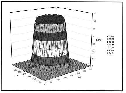
Figure 2 - Typical SPCM-AQ-1XY Photon Detection Scan @ 650 nm.
Figure 3 - Typical SPCM-AQ-2XY Photon Detection Scan @ 650 nm.
Figure 4 - Typical Correction Factor.
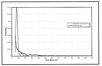
Figure 5 - Typical After Pulse Probability.
Figure 6 - Optical Power vs Number of Photons at Various
Wavelengths
Saturation At higher incoming light levels, the count decreases. The count at which the output rate starts to decrease is called the saturation point. As an extreme example, if the module is exposed to intense light, the count rate will fall to zero. Consequently, in certain applications, some tests should be performed by the operator to ensure that a low count rate is not caused by detector saturation. Some precaution shall be taken to avoid any damage of the SPCM module: first, do not expose the detector to room light when the module is being powered up. Secondly, do not power up the module when the detector is exposed to a photon rate above 1Mc/s.
Timing Resolution If the 300 ps FWHM (SPCM-AQ-1XY) timing resolution is inadequate, then the SPCM-PQ- CD2027 is currently available with a lower timing resolution. Call the factory for details.
Light Emission During Photon Detection One peculiarity of silicon avalanche photodiodes is that as an incoming photon is detected, a small amount of light is emitted from the avalanche region. The light emitted has a broad spectral distribution. In most cases this is not a problem. However, it can cause some confusion if another detector is monitoring light, or if the optical system is such that light emitted from the SPCM-AQ is reflected back on itself. If these photons return after more than 30 ns after the initial event, then they will be detected.
Safety The SPCM-AQ contains a high voltage power supply. All internal settings are preset; there are no user adjustments. Units which appear defective or have suffered mechanical damage should not be used because of possible electrical shorting of the high voltage power supply.
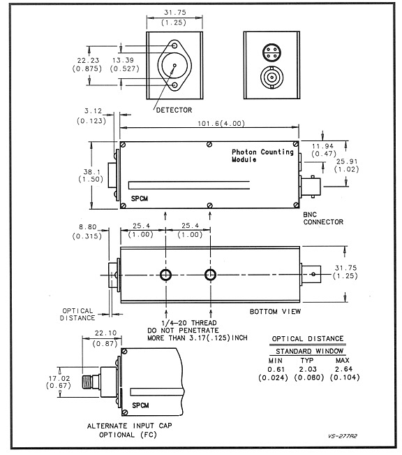
Figure 7
Figure 8
Figure 9 - Electrical Connections
Note: The shield must be connected to the ground wire at the power supply end. This has been done in the 1 meter cable supplied. The digital output pulse, ³ 2.0V, should be terminated with a 50 W load to avoid distortion and ringing. A 1.0V triggering level is recommended.
| ||||||||||||||||||||||||||||||||||||||||||||||||||||||||||||||||||||||||||||||||||||||||||||||||||||||||||||||||||||||||||||||||||||||||||||||||||||||||||||||||||||||||||||||||||||||||||||||||||||||||||||||||||||||||||||||||||||||||||||||||||||||||||||||||||||||||||||||||||||||||||||||||||||||||||||||||||||||||||||||||||||||||||||||||||||||||||||||||||||||||||||||||||||||||||||||||||||||