- Research
- Open access
- Published:
MDP-based handover policy in wireless relay systems
EURASIP Journal on Wireless Communications and Networking volume 2012, Article number: 358 (2012)
Abstract
Wireless relay transmission has been considered as a supplementary technology for future wireless communication system, and handover is a key element in wireless relay transmissions to support users’ mobility. Handover failure will result in the forced termination of an ongoing call, and a good handover scheme will provide good system performance. This article focuses on the handover decision problem in wireless relay transmission systems. Initially, the architecture of a single-cell relay system is introduced. The handover decision problem is formulated as a Markov decision process (MDP). In the proposed model, a profit function is used to evaluate the quality-of-service of the chosen serving node, and a cost function is used to model processing load and signaling cost. Based on the profit and cost functions, the reward function is formulated. Moreover, the objective is to maximize the expected total reward per connection. The value iteration algorithm is employed to determine the optimal handover policy. Furthermore, the analysis is generalized to multi-cell relay systems. Numerical results show that the proposed MDP-based handover policy is well behaved in wireless relay systems.
1 Introduction
Recently, wireless communications have been developing very rapidly from code division multiple access to orthogonal frequency division multiple access (OFDMA) techniques [1–3]. As the fast growing of users’ demands, the new generation wireless communication systems will provide high data rate and wide coverage. However, due to the restriction of scarce spectrum resources, the spectral efficiency of the new generation wireless communication systems is very limited [4]. The relay transmission, which deploys multiple relay nodes between a source node and a destination node, has attracted much attention in recent years. Due to its great potential to improve spectral efficiency and coverage area, relay transmission has been considered as a supplementary technology for the new generation wireless communication systems. As a result, the IEEE 802.11 Task Group and 802.16 Task Group are actively working on the standardization of relay transmission protocols [5, 6].
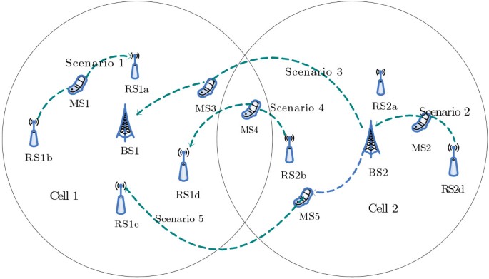
The basic idea of wireless relay transmission was introduced by van der Meulen [7], and was comprehensively studied by Cover and El Gamal [8]. So far, wireless relay transmission has been investigated in various aspects, including information-theoretic capacity [9, 10], diversity [11], outage performance [12], network coding [13], and power allocation [14, 15]. It should be noted that handover [16, 17], which provides the seamless mobility, is also an important issue in wireless relay systems. In conventional cellular systems, handover occurs only when a mobile station (MS) moves to different cells or different sectors of the same cell. However, the introduction of relay stations (RSs) in cellular systems creates additional handover scenarios. Figure 1 depicts diverse handover scenarios in wireless relay systems [18]. In scenario 1, an MS performs handover between two different RSs in the same cell. In scenario 2, an MS changes its communication node from a base station (BS) to the RS of the same cell, or vice versa. Scenario 3 is exactly the same as the inter-BS handover in the conventional cellular systems. In scenario 4, an MS performs handover from an RS to the RS of different cells. Scenario 5 is the process of an MS moves from a BS to the RS of different cells. Each mobile connection may experience a number of handovers during its lifetime connection. An efficient handover decision policy is beneficial to the system performance. Therefore, the handover is an important problem in wireless relay transmission systems. Recently, the handover schemes in wireless relay transmission systems have been defined in the base line document for the draft standard of IEEE 802.16j [6].
The handover policies for wireless communications have been reported in some literatures. Stemm and Katz [19] proposed a vertical handover scheme, where the handover decisions only depend on the presence or absence of beacon packets. A series of researches about handover based on the received signal strength have been carried out. In [20], the handover algorithms based on the received signal strength were reviewed, and advanced techniques (such as hypothesis testing, dynamic programming, and pattern recognition based on neural networks or fuzzy logic) were mentioned. An adaptive timer handoff (ATHO) algorithm was proposed in [21], which was based on the received signal strength with a hysteresis timer to adapt the ping-pong effect in mobile communication systems. In [22], a practical approach based on GSM measurement data was employed, and a handover algorithm was proposed to improve the handover performance. Jiang et al. [23] proposed a novel scheme using uplink and downlink signals for intra multi-hop relay BS handover with transparent RS. In [24], an optimization handover scheme for mobile users was proposed to minimize the delay and maximize the throughput by employing a dwell-timer. Although all above works have investigated the handover problems in wireless systems, the link quality conditions are only taken as the handover decision criteria, and the quality-of-service (QoS) and the processing load during handovers are not considered. To the best of the authors’ knowledge, few previous studies take the QoS and processing load together as the handover criteria in wireless relay systems.
In this article, we focus this study on a handover policy in wireless relay systems. At first, a relay transmission system with a single cell is introduced. In order to obtain better system performance, the adaptive modulation and coding schemes are employed. Furthermore, the available transmission rates for both the direct transmission and relay transmission links have been analyzed. Due to the mobility of MSs, a handover decision problem is then considered, which is formulated as a Markov decision process (MDP). After that, a profit function is used to evaluate the QoS of the chosen serving node, which represents the benefit that the MS can gain by choosing a serving node (i.e., the BS or some RS). The cost function is also considered, which captures the processing and signal load incurred when the connection switch the current serving node to another. Based on the profit and cost functions, the reward function is formulated. The objective of the handover problem is to maximize the expected total reward per connection. An optimal MDP-based handover decision policy is proposed by employing the value iteration algorithm (VIA). Furthermore, the proposed MDP-based handover policy is generalized to multi-cell relay systems.
The remainder of this article is organized as follows. The system model is described in Section 2. Section 3 formulates the handover decision process as an MDP, after that the optimality equations and the VIA are proposed. Extensions to multiple cell systems are discussed in Section 4. Numerical results are presented in Section 5 before conclusions are drawn in Section 6.
2 System model
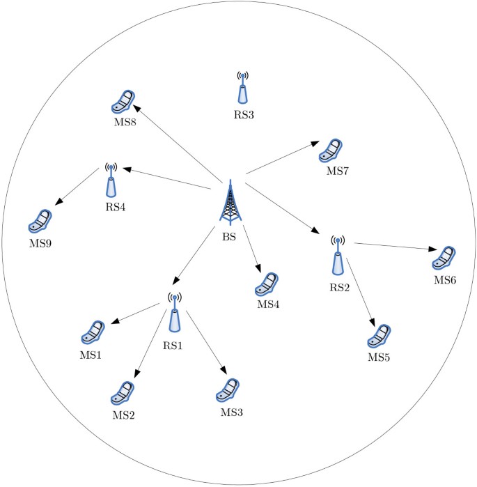
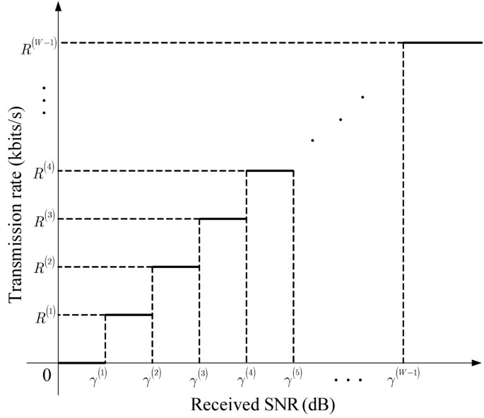
Consider the downlink transmission of a single-cell relay system, which is composed of one BS, M RSs, and multiple MSs, as shown in Figure 2. The BS can communicate with MSs directly or with the help of one RS. Depending on whether the BS communicates with MSs directly or with the help of RS, the transmissions can be classified into direct transmission and relay transmission. Moreover, the transmit power of BS (RS) is equally distributed to its serving MSs. Here, each MS is assumed to operate in a pre-assigned orthogonal channel, such as non-overlapping time/frequency slot. This assumption holds for most practical systems such as time division multiple access, frequency division multiple access (FDMA), and OFDMA systems [25]. Therefore, no inter-channel interferences exist among all MSs. In order to maximize system performance, the adaptive modulation and coding schemes are employed. Assuming that the BS or RSs can transmit data to the MS with W − 1 nonzero fixed transmission rates, which can be denoted as R(1),…,R(W−1). Without loss of generality, we suppose that R(W−1) > ⋯ > R(1) > 0. If zero is regarded as one special transmission rate, the set of downlink transmission rates can be denoted as Λ = {R(0}R(1),…,R(W−1)), where R(0) = 0. To guarantee the receiving accuracy of certain downlink transmission rate, it is expected that the received signal-to-noise ratio (SNR) must be no less than the target SNR. For a downlink transmission rate R(ω)(ω=0,1,…,W−1), the corresponding target SNR is denoted by γ(ω). Obviously, these target SNRs should satisfy
When the received SNR γ∈[γ(ω),γ(ω + 1)), the transmission rate can be determined by R(ω) at most. Mathematically, given a received SNR γ, the transmission rate r can be obtained by
where U(t−t0) is the Heaviside unit step function defined by
Note that the relationship between the received SNR γ and the transmission rate r can be seen in Figure 3.
For the direct transmission case, an MS can receive signal from the BS directly. The received downlink signal y0 can be expressed as
where P0 denotes the total transmit power of the BS, N0 is the number of MSs served by the BS, x0 is the transmitted information symbol with unit energy at the BS, G0 is the channel gain between the BS and the MS, and z0is the additive white Gaussian noise. Without loss of generality, we assume that the noise level is the same for all links and is denoted by σ2. Then, the directly received SNR γ0 can be expressed as
Therefore, in this case, the maximum transmission rate r0 can be obtained by
For the relay transmission case, we concentrate on the BS–RSm–MS link. In this case, the transmission consists of two phases. In phase 1, the BS first transmits the information to RS m, which is selected to relay the information. Therefore, the received signals at RS m can be expressed as
where is the number of the RSs served by the BS in phase 1, is the channel gain between the BS and RS m, is the received additive white Gaussian noise. Therefore, the received SNR at RS m can be derived as
Therefore, the transmission rate on the link between the BS and RS m can be obtained by
In phase 2, amplify-and-forward relay transmission strategy is employed [26], that is, RS m amplifies with transmission power and forwards it to the MS, where P m is the total transmit power of RS m and is the numbers of MSs served by RS m in phase 2. Accordingly, the received signal of the MS can be expressed as
where
is the unit-energy transmitted signal that RS m received from the BS in phase 1, is the channel gain between RS m and the MS, and is the received noise at the MS. Then, in this phase, the received SNR at the MS can be expressed as
Accordingly, the transmission rate in phase 2 can be obtained by
Finally, the available transmission rate on the BS–RSm–MS link can be determined as
where the coefficient 1/2 is due to the fact that cooperative transmission uses half of the resources (e.g., time slots, frequency bands, orthogonal codes).
Due to the mobility, each MS will monitor the whole system all the time and has the choices of communicating directly with the BS or with the help of one RS, which involves the handover decision problems. The following section will solve this handover problem using MDP.
3 MDP-based handover decision
MDP, also referred to as stochastic dynamic programs or stochastic control problems, are models for sequential decision making when outcomes are uncertain. The MDP model consists of decision epochs, states, actions, rewards, and transition probabilities [27]. Choosing an action in a state generates a reward and determines the state at the next decision epoch through a transition probability function. Policies or strategies are prescriptions of which action to choose under any eventuality at every future decision epoch. Decision makers seek policies which are optimal in some sense. MDP has already been successfully used to solve a variety of problems, including finance [28], admission control [29], mobility-related issues in the areas of mobile communications, and in wireless sensor networks [30, 31]. Therefore, MDP is a promising candidate in solving the handover control problems in wireless relay systems.
In the following, we will describe how the handover decision problem is formulated as an MDP. Then, the optimality equations and the VIA are introduced. To facilitate the description, in the following, the BS and all RSs are also called as serving nodes. Specially, the serving node 0 refers to the BS and the serving node m (m =1,…,M) refers to RS m.
3.1 Decision epoch, action, and state
Referring to Figure 4, the sequence T = {1,2,…,Q} represents the time of successive decision epochs, and the random variable Q denotes the time that the connection terminates. At each decision epoch, the MS has to decide whether the connection should use the current serving node or choose another serving node based on its current state. In this article, the state space of an MS is denoted by S, and the number of states that an MS can possibly be in is finite. The state of the MS contains information such as the current serving node that the MS connects to, and the available transmission rates that all serving nodes offer. Specifically, the state space can be expressed as follows
where “×” denotes the Cartesian product, {0,1,2,…,M} denotes the set of current serving nodes that the MS connects to, R0denotes the set of the available transmission rates on the direct transmission link, and R m (m=1,…,M) denotes the set of the available transmission rates on the BS–RSm–MS link. Obviously, it can be known that R0 = Λ. Furthermore, according to Equation (14), R m can be derived as
Based on the current state, the MS has to choose an action at each decision epoch. Considering the MS can only select a serving node from the BS and all RSs, the action set can be defined as , where A consists of all the serving nodes that MS can handover to.
3.2 Transition probability
Let vector s (t) = [i,r0,r1,…,r M ] denote the state of the MS at the t th decision epoch, where i denotes the current chosen serving node, r0denotes the current available transmission rate on the direct transmission link, r m (m=1,…,M) denotes the current available transmission rate on the BS–RSm–MS link. Based on the current state s(t), if the chosen action is a(t)=j, the probability transition function that the next state is given by
where denotes the transition probability of the transmission rate of the serving node m. Although all serving nodes are collected in the system, the transmission rate of each serving node is only rely on the number of users supported by the serving node and the channel gain between the node and the MS. Therefore, the transition probability of the transmission rate of each serving node in Equation (17) is assumed to be independent with each other. Specially, if the values of the transmission rates are guaranteed for the duration of the connection, the transition probability in this special case can be expressed as
Note that the functions (17) and (18) are Markovian because the state transition probability only depends on the current state and action but not on the previous states.
3.3 Reward function
Let z(s(t),a(t)) denote the reward that the MS receives after the tthdecision epoch. In this section, the reward function is defined as
where f (s (t) , a (t)) is the profit function and reflects the QoS provided by the chosen serving node at the tth decision epoch. g (s (t) , a (t)) denotes the cost function, which captures the processing and signal load incurred when the connection switch the current serving node to another.
Given the current state s (t) = [i,r0,r1,…,r M ], where i denotes the current serving node used by the connection, r m denotes the available rate provided by serving node m. At each decision epoch, based on the current state s(t), the MS should choose an action a(t)∈A. Therefore, the profit function can be defined as
The profit function (in terms of transmission rate) can be assessed as follows. Given that the MS is currently connecting to serving node i, if serving node i is the one which supports the highest rate among others and the chosen action a (t) = i, the profit is set to be 1, otherwise, the profit is set to be 0. However, when serving node i is not the one which supports the highest rate, the profit that it can obtain is represented by a fraction, in which the numerator is the MS’s actual increase of rate by choosing action a (t) in state s (t), and the denominator is the MS’s maximum possible increase of rate.
The cost function g (s (t),a (t)) is defined as
It can be known from Equation (21) that, when the new serving node a (t) is the same as the current serving node i (i.e., a (t) = i), there is no handover happens, and thus the cost is set to be zero. However, when the new serving node a (t) is different from the current serving node i (i.e., a (t) ≠ i), the handover will happen, and the cost in this case is set to be Ki,a(t). Note that Ki,a(t) denotes the switching cost from the current serving node i to the new serving node a (t). The value of Ki,a(t) depends on several factors, such as the types of handover and the current traffic load on the serving node.
3.4 Expected total reward
A decision rule prescribes a procedure for action selection in each state at a specified decision epoch. Deterministic Markov decision rules are functions δ (t) : S → A, which specify the action choice a (t) when the system occupies state s (t) at the t th decision epoch. A policy Π = (δ (1) , δ (2) ,…,δ (Q)) is a sequence of decision rules to be used at all decision epochs.
Let vΠ(s(0)) denote the expected total reward from the first decision epoch until the handover decision period elapses, given that the policy Π is used with an initial state s(0). We have
where denotes the expectation with respect to policy Π and initial state s(0), and E Q denotes the expectation with respect to random variable Q. Note that a different policy Π and initial state s(0) will change the chosen action a(t). This will also cause a different transition probability function P [ s (t + 1])| s (t), a (t)| to be used in the expectation . The random variable Q, which denotes the connection termination time, is assumed to be geometrically distributed with mean 1/(1−λ)[32]. That is
Therefore, Equation (22) can be further written as
Since , by interchanging the order of the summation, we have
where λ∈[0,1) is the discount factor of the model.
Our optimization problem is to maximize the expected total discounted reward. The Π∗ is defined to be the optimal policy in π if for all Π ∈ π. A policy is said to be stationary if δ (t) = δ for all t. A stationary policy has the form Π = (δ,δ,…,δ). For convenience, Π is denoted as δ. Our objective is to determine an optimal stationary deterministic policy δ∗, which maximizes the expected total discounted reward given by Equation (25).
3.5 Optimality equations and the VIA
In this section, the optimality equations which maximize the expected total reward are proposed, and following that, a VIA is used to determine a stationary optimal handover policy.
Let v(s) denote the maximum expected total reward, given the initial state s. That is
Referring to [27], the optimality equations can be written as
where s′ denotes the next state while we select action a in state s. The solutions of the optimality equations correspond to the maximum expected total reward v(s) and the MDP optimal policy δ∗(s). Note that the MDP optimal policy δ∗(s) indicates the decision as to which node to choose from, given that the current state is s.
The VIA [27, 32] is employed in this article to determine a stationary deterministic optimal policy and the corresponding expected total reward. The stepwise procedures of the VIA algorithm are described as follows:
-
Step (1): Set v0(s) = 0 for each state s. Specify ε>0 and set k=0 .
-
Step (2): For each state s, compute vk + 1(s) by using
-
Step (3): If ∥vk + 1−vk∥<ε(1−λ)/2λ thenGo to Step (4).ElseLet k=k + 1, and return to Step (2).EndIf
-
Step (4): For each state sεS, compute the stationary optimal policy by using
-
Step (5): Stop.
In the VIA, the normal function ∥·∥ is defined as ∥v∥ = max|v(s|) for s ∈ S. Note that the VIA is convergent because the operation in Step (2) corresponds to a contraction mapping. Each iteration of the VIA is performed in O (|A)|S|2|, i.e., the convergence rate of the VIA is linear.
A stationary deterministic optimal policy table can be created according to this algorithm. The MSs are assumed to periodically receive information from the serving nodes. The advertised information from each serving node may include, among other parameters, the achieved transmission rate and the handover cost. In each time of period, the MSs decide whether the connection should use the current serving node or reroute to another serving node according to the stationary deterministic optimal policy table.
4 Extensions to multiple cell systems
The proposed MDP-based handover policy can be generalized to multi-cell systems. Assuming that there are E cells in the system, and each cell has one BS and N RSs. Let us define B e (e=1,2,…,E) as the BS in cell e, and define as the RS n in cell e. Then, the directly received signal-to-interference-plus noise ratio (SINR) provided by BS e can be expressed as
where is the total transmit power of BS e, is the number of nodes (i.e., MSs in direct transmission case) served by BS e, and is the channel gain from BS e to the MS, denotes the inter-cell interference (ICI). Therefore, in this case, the actual available maximum direct transmission rate can be obtained by
For the relay transmission case, the SINR at RS n of cell e in phase 1 can be derived as
where is the number of nodes (i.e., RSs in phase 1 of the relay transmission case) served by BS e, is the channel gain between the BS and RS n in cell e, and is the ICI. Then, the transmission rate on the BS- link in cell e can be obtained by
Similarly, in phase 2, the received SINR on the -MS link in cell e can be expressed as
where is the total transmit power of RS n in cell e, is the number of MSs served by RS n in cell e, and are the channel gain and ICI from RS n to the MS in cell e. Then, the transmission rate on the -MS link in cell e can be obtained by
Therefore, the available rate of the MS on the BS e ––MS link can be expressed as
According to MDP, the action set can be defined as , and the state space can be expressed as
where denotes the set of the available transmission rate of the BS in cell e, and denotes the set of the available transmission rate of RS n in cell e.
Similar to the single-cell system, the handover decision policy can be determined by VIA. Note that, the introduction of multiple-cell systems will result in the increase of the state space of MDP. Obviously, computational complexity will increase accordingly.
5 Numerical results
In order to evaluate the performance, it is desired to compare our proposed MDP-based handover policy with other policies through computer simulations. Unfortunately, to the best of the authors’ knowledge, few previous studies take the QoS and processing load together as the handover criteria in wireless relay systems. Here, a nearest distance handover policy and a biggest channel gain handover policy are taken as the comparative policies. In the nearest distance handover policy, each MS chooses the nearest serving node at each decision epoch. In the biggest channel gain handover policy, the serving node to be selected in each decision epoch is the one that has the biggest channel gain. Then, under the same simulation environments, the numerical results of the proposed MDP-based handover policy are compared with the nearest distance handover policy and the biggest channel gain handover policy.
A single-cell wireless relay system is used as the test system. In the system, all serving nodes and MSs are located in a square area with 2000-m side length. Specifically, the BS is located in the center of the cell and its coordinate is set to be (0 m, 0 m). To simplify the dimension of the state space, four RSs are configured in the cell, which are located at (600 m, 0 m), (0 m, 600 m), (−600 m, 0 m), and (0 m, −600 m), respectively. The initial positions of all MSs are randomly generated in the cell. A mobility pattern is employed for each MS, i.e., the speed of each MS follows uniform distribution in the range of [0,3] m/s, and the direction of each MS is uniformly distributed in the range of [0,2Π. To ensure that each MS always locates in the coverage of the cell, once the MS arrives at the boundary of the cell, we let the MS moves along the reverse direction of the current direction. Referring to [33], the channel gain is modeled as Y/L(l), where Y accounts for the loss of shadow fading and follows a lognormal distribution with variance . L(l) is the path loss between the transmitter and the receiver, and can be calculated from 10log10L(l)=128. 1 + 37. 6log10l, where l (in kilometers) represents the distance between the transmitter and the receiver. The background noise level is set to be −104 dBm. In the simulation, the set of the modulation and coding schemes consists of 1/2-BPSK, 1/2-QPSK, 2/3-QPSK, 5/6-QPSK, 1/2-16QAM, and 2/3-16QAM, where their thresholds of SNR maintaining the target BER of 10−3can be found in Table 1[34]. Then, the set of downlink transmission rates can be denoted as
where the symbol rate c is set to be 640 ksymbols/s. Moreover, we use a simulation-based method to estimate the state transition probability. For more detailed description of this method, the readers can refer to [32]. The other simulation parameters of the system are summarized in Table 2. In the following, the system transmission rates (i.e., the average transmission rates of every MS) and the expected total reward per connection will be used as the performance metrics.
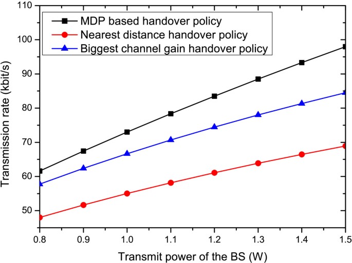
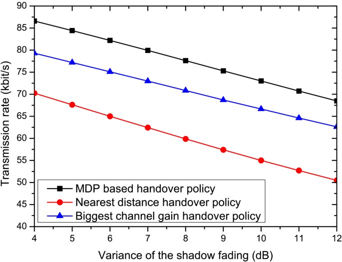
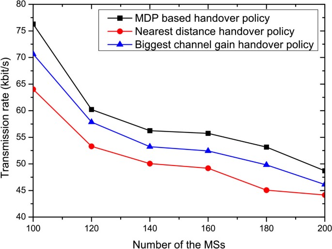
Figures 5, 6, and 7 illustrate the system transmission rates of the three policies in different scenarios. Specifically, Figure 5 plots the system transmission rates versus the transmit power of the BS, where the transmit power of each RS is set to be 10 mW and the number of MSs in the cellular is set to be 100. It can be observed that, with the increase of the transmit power of the BS, the received SNR of each MS will also increase. Accordingly, a better adaptive modulation and coding scheme will be selected, which results in a greater system transmission rate. Moreover, it can be found that the transmission rates of the proposed MDP-based handover policy are always greater than that of the nearest distance handover policy and the biggest channel gain handover policy, actually, about more than 25 and 10%, respectively. That is to say, the performance of handover has been improved by employing the proposed MDP-based handover policy in wireless relay systems.
Figure 6 shows the relationship between the system transmission rates and the variance of shadow fading. In this simulation, there are 100 MSs in the system, the transmit power of each RS is fixed to be 10 mW, the transmit power of the BS is set to be 1 W, and the variance of the shadow fading is increasing from 4dB to 12 dB. It can be observed from Figure 6 that the system transmission rates decrease with the increase of the variance of the shadow fading. The reason is that, when the variance of the shadow fading increases, the channel fading becomes worse, and then the received SNR of each MS will decrease. Accordingly, the system transmission rates will be affected. Moreover, compared with the other two policies, the proposed MDP-based handover policy can consistently achieve the biggest transmission rate, which indicates that the proposed policy is well behaved.
Figure 7 depicts the system transmission rates versus the number of MSs, where the transmit power of the BS is set to be 1 W and the transmit power of each RS is set to be 10 mW. In Figure 7, the transmission rates of the three policies are shown to be decreased with the increase of the number of the MSs. This is due to the fact that, the power resource will be allocated to more MSs with the increase of the number of the MSs. Once again, it should be noted that the proposed MDP-based handover policy always outperforms the other two policies in terms of the system transmission rate, which also proves that the proposed MDP-based handover policy is well behaved.
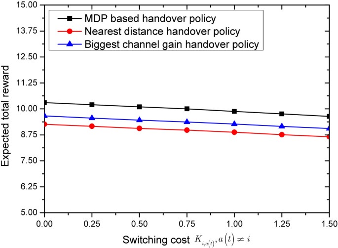
Figures 8 and 9 illustrate the expected total rewards of the three policies in different scenarios. Specifically, Figure 8 shows the expected total reward versus the switching cost between every two different serving nodes (i.e., Ki,a(t),a (t) ≠ i). In Figure 8, with the increase of the switching cost, the expected total rewards of all three policies decrease. This indicates that the switching cost provides flexibility for the system operators. In other words, small values of the switching cost can be set among serving nodes with light signaling load, while large values of the switching cost can temporarily be set for overload serving nodes as a load-balancing technique to decrease the traffic load in the system. Moreover, the proposed MDP-based handover policy always keeps the biggest expected total reward compared to the other two policies, which means the proposed MDP-based handover policy achieves the best performance in terms of the expected total reward.
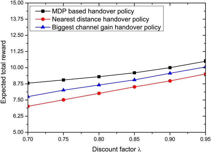
Figure 9 shows the expected total reward versus the discount factor λ. It can be seen that the expected total rewards of the three policies increase with the increase of the discount factor. This conclusion can directly be derived from Equation (25) or (27). Moreover, compared to the other two policies, the MDP-based handover policy can consistently provide the highest expected total reward per connection for all values of λ. For example, when the discount factor is 0.9, the MDP-based handover policy can obtain 10 and 4% more total expected total reward than the nearest distance handover policy and the biggest channel gain handover policy, respectively. Once again, it should be noted that the proposed MDP-based handover policy is well behaved in wireless relay systems.
6 Conclusion
This article has focused on the handover decision problem in wireless relay transmission systems. The architecture of the single-cell relay system is first introduced. Then, the handover decision problem is formulated as an MDP. A profit function is used to evaluate the QoS of the chosen serving node, and a cost function is used to model the signaling cost. Based on the two functions, a reward function is formulated. After that, in order to maximize the expected total reward per connection, a stationary deterministic optimal policy is obtained by employing the VIA. Furthermore, we have shown that the proposed MDP-based handover policy can be generalized to multiple-cell systems. Numerical results show that the MDP-based handover policy proposed in this article is well behaved in solving the handover problem of wireless relay systems.
Abbreviations
- BS:
-
Base station
- FDMA:
-
Frequency division multiple access
- MDP:
-
Markov decision process
- MS:
-
Mobile station
- OFDMA:
-
Orthogonal frequency division multiple access
- QoS:
-
Quality-of-service
- RSs:
-
Relay stations
- SINR:
-
Signal-to-interference-plus-noise ratio
- SNR:
-
Signal-to-noise ratio.
References
Wang J, Chen J: Performance of wideband CDMA systems with complex spreading and imperfect channel estimation. IEEE J. Sel. Areas Commun 2001, 19(1):152-163. 10.1109/49.909617
Wang J-B, Chen M, Wan X, Wei C: Ant-colony-optimization-based scheduling algorithm for uplink CDMA nonreal-time data. IEEE Trans. Veh. Technol 2009, 58(1):231-241.
Zhu H, Wang J, Chunk-based resource allocation in OFDMA systems—Part: I chunk allocation: IEEE Trans. Commun. 2009, 57(9):2734-2744.
Wang J-B, Chen M: Optimal uplink packet scheduling for CDMA non-real time data. IEE Electron. Lett 2007, 43(14):764-766. 10.1049/el:20070786
IEEE: Draft Standard for Local and Metropolitan Area Networks—Part 16: Air Interface for Fixed and Mobile Broadband Wireless Access Systems: Multihop Relay Specification. IEEE Standard 2007. 2007. 4312731
IEEE: Part 16: Air Interface for Fixed and Mobile Broadband Wireless Access Systems: Multihop Relay Specification, IEEE P802.16j Base Line Document. 2007.
van der Meulen EC, Three-terminal communication channels: Adv. Appl. Probab. 1971, 3(1):120-154. 10.2307/1426331
Cover TM, El Gamal AA: Capacity theorems for the relay channel. IEEE Trans. Inf. Theory 1979, IT-25(5):572-584.
Lei X, Li W: Exact closed-form expression for ergodic capacity of amplify-and-forward relaying in channel-noise-assisted cooperative networks with relay selection. IEEE Commun. Lett 2011, 15(3):332-333.
Ding Y, Zhang J-K, Wong KM: Ergodic channel capacities for the amplify-and-forward half-duplex cooperative systems. IEEE Trans. Inf. Theory 2009, 55(2):713-730.
Kwon U-K, Choi C-H, Im G-H: Full-rate cooperative communications with spatial diversity for half-duplex uplink relay channels. IEEE Trans. Wirel. Commun 2009, 8(11):5449-5454.
Wang J-B, Jiao Y, Chen M, Wang J-Y, Cao Z: Multi-hop free space optical communications using serial decode-and-forward relay transmissions. China Commun 2011, 8(5):102-110.
Ding Z, Leung KK, Goeckel DL, Towsley D: On the study of network coding with diversity. IEEE Trans. Wirel. Commun 2009, 8(3):1247-1259.
Luo J, Blum RS, Cimini LJ, Greenstein LJ, Haimovich AM: Decode-and-forward cooperative diversity with power allocation in wireless networks. IEEE Trans. Wirel. Commun 2007, 6(3):793-799.
Ng TC-Y, Yu W: Joint optimization of relay strategies and resource allocations in cooperative cellular networks. IEEE J. Sel. Areas Commun 2007, 25(2):328-339.
Pabst R, Walke BH, Schultz DC, Herhold P, Yanikomeroglu H, Mukherjee S, Viswanathan H, Lott M, Zirwas W, Dohler M, Aghvami H, Falconer DD, Fettweis GP: Relay-based deployment concepts for wireless and mobile broadband radio. IEEE Commun. Mag 2004, 42(9):80-89. 10.1109/MCOM.2004.1336724
Wu H, Qiao C, De S, Tonguz O: Integrated cellular and ad hoc relaying systems: iCAR. IEEE J. Sel. Areas Commun 2001, 19(10):2105-2115. 10.1109/49.957326
Cho S, Jang EW, Cioffi JM: Handover in multihop cellular networks. IEEE Commun. Mag 2009, 47(7):64-73.
Stemm M, Katz RH: Vertical handoffs in wireless overlay networks. ACM/Baltzer Mobile Netw. Appl 1998, 3(4):335-350. 10.1023/A:1019197320544
Pahlavan K, Krishnamurthy P, Hatami A, Ylianttila M, Makela JP, Pichna R, Vallstron J: Handoff in hybrid mobile data networks. IEEE Personal Commun 2000, 7(2):34-47. 10.1109/98.839330
Huang Y-F, Gao F-B, Hsu H-C: Performance of an adaptive timer-based handoff scheme for wireless mobile communications. In Proceedings of the 10th WSEAS International Conference on Signal Processing, Computational Geometry and Artificial Vision. Stevens Point, Wisconsin, USA; 2010:46-51.
Lin H-P, Juang R-T, Lin D-B: Validation of an improved location-based handover algorithm using GSM measurement data. IEEE Trans. Mobile Comput 2005, 4(5):530-536.
Jiang J, Heng W, Zhang H, Wu G, Wang H: A novel handover scheme for multi-hop transparent relay network. In Proceedings of the International Conference on Wireless Communications & Signal Processing. Nanjing, China; November 2009:1-5.
Ylianttila M, Pande M, Makela J, Mahonen P: Optimization scheme for mobile users performing vertical handoffs between IEEE 802.11 and GPRS/EDGE networks. In Proceedings of the IEEE Global Telecommunications Conference. San Antonio, TX, USA; November 2001:3439-3443.
Wang J-B, Chen H, Chen M, Wang J: Cross-layer packet scheduling for downlink multiuser OFDM systems. Sci. China Ser. F - Inf. Sci 2009, 52(12):2369-2377. 10.1007/s11432-009-0219-1
Li W, Wang J-B, Chen M: Outage probability of dual-hop amplify-and-forward relaying systems over shadowed Nakagami-m fading channel. IEICE Trans. Fund. Electron. Commun. Comput. Sci 2008, 91(11):3403-3405.
Puterman M: Markov Decision Processes: Discrete Stochastic Dynamic Programming. Wiley, Hoboken, NJ; 1994.
Feinberg EA, Schwartz A, Feinberg EA: Handbook of Markov decision processes, ch. Markov Decision Processes in Finance and Dynamic Options. Kluwer, Netherlands; 2002.
Yu F, Krishnamurthy V, Leung VCM: Cross-layer optimal connection admission control for variable bit rate multimedia traffic in packet wireless CDMA networks. IEEE Trans. Signal Process 2006, 54(2):542-555.
Yu F, Wong VWS, Leung VCM: Efficient QoS provisioning for adaptive multimedia in mobile communication networks by reinforcement learning. Mobile Netw. Appl 2006, 11(1):101-110. 10.1007/s11036-005-4464-2
Tham CK, Renaud JC: Multi-agent systems on sensor networks: a distributed reinforcement learning pproach. In Proceedings of the Second International Conference on Intelligent Sensors, Sensor Networks and Information Processing. Melbourne, Australia; December 2005:423-429.
Stevens-Navarro E, Lin Y, Wong VWS: An MDP-based vertical handoff decision algorithm for heterogeneous wireless networks. IEEE Trans. Veh. Technol 2008, 57(2):1243-1254.
UMTS: Annex B: Test Environments and Deployment Models. 1998. UMTS 30.03
Moon J, Hong S: Adaptive code-rate and modulation for multi-user OFDM system in wireless communications. In Proceedings of the IEEE 56th Vehicular Technology Conference. Vancouver, Canada; September 2002:1943-1947.
Acknowledgements
The authors would like to acknowledge the funding assistance of National Natural Science Foundation of China (No. 61172078).
Author information
Authors and Affiliations
Corresponding author
Additional information
Competing interests
The authors declare that they have no competing interests.
Authors’ original submitted files for images
Below are the links to the authors’ original submitted files for images.
Rights and permissions
Open Access This article is distributed under the terms of the Creative Commons Attribution 2.0 International License ( https://creativecommons.org/licenses/by/2.0 ), which permits unrestricted use, distribution, and reproduction in any medium, provided the original work is properly cited.
About this article
Cite this article
Dang, X., Wang, JY. & Cao, Z. MDP-based handover policy in wireless relay systems. J Wireless Com Network 2012, 358 (2012). https://doi.org/10.1186/1687-1499-2012-358
Received:
Accepted:
Published:
DOI: https://doi.org/10.1186/1687-1499-2012-358
