Abstract
Continuum manipulators, inspired by nature, have drawn significant interest within the robotics community. They can facilitate motion within complex environments where traditional rigid robots may be ineffective, while maintaining a reasonable degree of precision. Soft continuum manipulators have emerged as a growing subfield of continuum robotics, with promise for applications requiring high compliance, including certain medical procedures. This has driven demand for new control schemes designed to precisely control these highly flexible manipulators, whose kinematics may be sensitive to external loads, such as gravity. This article presents one such approach, utilizing a rapidly computed kinematic model based on Cosserat rod theory, coupled with sensor feedback to facilitate closed-loop control, for a soft continuum manipulator under tip follower actuation and external loading. This approach is suited to soft manipulators undergoing quasi-static deployment, where actuators apply a follower wrench (i.e., one that is in a constant body frame direction regardless of robot configuration) anywhere along the continuum structure, as can be done in water-jet propulsion. In this article we apply the framework specifically to a tip actuated soft continuum manipulator. The proposed control scheme employs both actuator feedback and pose feedback. The actuator feedback is utilized to both regulate the follower load and to compensate for non-linearities of the actuation system that can introduce kinematic model error. Pose feedback is required to maintain accurate path following. Experimental results demonstrate successful path following with the closed-loop control scheme, with significant performance improvements gained through the use of sensor feedback when compared with the open-loop case.
Keywords: Mechanics, design and control, medical robots and systems, control architectures and programming
1. Introduction
Continuum manipulators, defined as flexible devices which take on curvilinear shapes as they are actuated, have proven useful in a variety of industries, from medicine to military applications (Singh and Krishna, 2014). The design of these devices is often biologically inspired, with motions mimicking those of elephant trunks or octopus tentacles (Walker et al., 2005). In comparison with traditional rigid robots, continuum robots possess several unique capabilities, such as whole-arm grasping and manipulation (Giri and Walker, 2011), navigation through complex and unpredictable environments (Chirikjian and Burdick, 1995), and passive compliance which can make them safer for interacting with humans (Sanan et al., 2011).
In the medical field especially, non-robotic versions of continuum devices have long been used in the form of steerable catheters for cardiovascular interventions, flexible endoscopes for inspecting the digestive tract and lungs, and providing access to remote surgical sites via small openings and non-linear pathways. When coupled with robotic actuation, these devices can become more precise, more dexterous and easier to use. Continuum robots for medical applications include robotic catheters (Rafii-Tari et al., 2014), robotic flexible endoscopes (Yeung and Chiu, 2016), multi-backbone snake robots (Simaan et al., 2009), concentric tube robots (Dupont et al., 2010; Garriga-Casanovas and Rodriguez y Baena, 2018; Gilbert et al., 2016; Rucker et al., 2010), and steerable needles (Scali et al., 2017; Webster et al., 2006). Although the flexibility of continuum robots provides many advantages for minimally invasive surgery, many designs are still too stiff for certain clinical applications, in which insufficient compliance of the manipulator increases the risk of inadvertent tissue damage (Bajo and Simaan, 2012; Mahvash and Dupont, 2011).
As the demand for more flexible robots has increased particularly within the medical industry, the field of “soft continuum robotics” has grown significantly. The use of soft, elastomeric materials for the construction of continuum robots has enabled researchers in this field to develop continuum manipulators with extremely low stiffnesses. As reviewed by Trivedi et al. (2008) and by Marchese and Rus (2016), soft manipulators are typically considered to be a subclass of continuum robots, though there is no widely agreed upon stiffness value which separates “soft continuum robots” from “hard continuum robots.” In this article, we focus on the subclass of soft continuum manipulators whose body is composed exclusively by soft elastic material (having Young’s modulus lower than 105 Pa) without the presence of any metallic components.
The vast majority of soft continuum manipulators presented to date can be categorized into one of two primary morphologies: (1) arms actuated through tension applied to tendons or cables running along their length (e.g., Calisti et al., 2011; Ranzani et al., 2015; Wang et al., 2013); and (2) arms composed of multiple chambers which can be pressurized by air or fluid to produce bending as a result of pressure differences within the robot’s cross-section (e.g., Deimel and Brock, 2013; Martinez et al., 2013). These two distinct morphologies have been investigated extensively in the literature from both modeling and control standpoints. They are similar in that they both involve distributed loads along a central “backbone.” Although in-plane bending often allows for the simplifying assumption that these actuation mechanisms apply only a tip moment to the backbone, this assumption breaks down when out-of-plane bending occurs, whether due to the actuation itself, such as in the case of non-linear tendon-routing, or due to external loads, such as those due to gravity (Rucker and Webster, 2011b).
In contrast, designs recently presented in Campisano et al. (2017) and Slawinski et al. (2017) involve forces and/or moments located only at the tip of the robot, which do not produce any significant distributed loads along the length of the backbone, even when out-of-plane bending occurs. In Slawinski et al. (2017), the soft manipulator is steered via a tip wrench generated by a permanent magnet mounted on and controlled via an industrial robot arm; in Campisano et al. (2017), the soft manipulator is actuated by water jets of controllable flow rates which spray out from the tip of the manipulator, producing a force on the tip. We refer to these designs as soft continuum manipulators under tip follower actuation (TFA) to highlight that the only source of actuation is a tip wrench, which follows along with the tip frame as the robot moves, and to differentiate them from the other two categories described previously.
The strategy adopted for modeling and control of a particular continuum manipulator, whether soft or hard, depends on many variables, including the type of actuation, material properties, and design geometry. The simplest modeling method for tendon-driven and pressurized chamber-actuated devices is the constant curvature (CC) model (for a review, see Webster and Jones, 2010). This approximation is based on the assumption that each degree of freedom (DoF) is independent and the deflected shape can be modeled as a perfect circular arc. Depending on the robot design and the required level of accuracy for the application, this modeling approach may suffice. However, as the device stiffness decreases and deflection increases, accuracy of the CC approximation is typically reduced, making it unsuitable for many applications, at least in the absence of a closed-loop controller (Marchese et al., 2014). An extension of the CC approximation is to discretize the manipulator into many short CC sections (Roesthuis and Misra, 2016; Rolf and Steil, 2014). In this approach, finer discretization provide more accurate models, but also present many more parameters in need of calibration.
Non-linear finite element analysis (FEA) has also proven useful for modeling the kinematics of soft continuum manipulators. Largilliere et al. (2015) showed that this method can accurately predict the displacement of a pressurized chamber-actuated soft continuum manipulator based on pre-computed strain maps for varying input pressures. However, this method proves to be highly sensitive to uncertainties in model parameters, as well as external disturbances, such as a change of the robot orientation with respect to gravity, making it challenging to apply this approach in a variety of practical applications.
A rigid-body approximation approach has been used extensively for devices commonly referred to as soft-tethered endoscopic capsules (Slawinski et al., 2015), whose body is characterized by a passive flexible tether attached to a capsule experiencing a point wrench. These devices, proposed as an alternative to endoluminal endoscopes, provide access to remote surgical sites by entering the human body via natural orifices. Taddese et al. (2016) steered the device within the colon through the application of a magnetic wrench on the capsule. For this application, the spatial configuration of the soft tether is not modeled, and the forces generated by the presence of the tether are treated as an external disturbance to the pose of the capsule’s body and compensated through the use of pose feedback. This has proven effective for motion in a closed lumen, where tissue interaction forces dominate over the loads applied on the capsule by the tether; however, when tip motion due to a TFA is controlled in free space, the forces applied on the capsule by the tether become relevant.
Given the limitations of these modeling approaches, forward kinematic models based on Cosserat rod theory have emerged as some of the most accurate models available for continuum manipulators. This approach involves integrating the constitutive differential equations for a rod-type structure subject to certain boundary conditions, as described for soft pressurized chamber-actuated robots in Trivedi et al. (2008). As in Trivedi’s work, Cosserat rod theory has been applied to tendon-actuated robots (Rucker and Webster, 2011b), concentric tube robots (Dupont et al., 2010; Rucker et al., 2010), and elastic rods with permanent magnets at the tip subject to spatially varying magnetic fields (Edelmann et al., 2017; Kratchman et al., 2017). Although Cosserat rod theory can be directly adapted to compute forward kinematics of these manipulators, it typically does not allow for direct inversion. Instead, a differential kinematics approach is typically used, in which the Jacobian matrix is used to map desired task space velocities into desired actuator space velocities. This forward kinematic model and resolved rates approach has proven effective, even without pose feedback, for stiff continuum robots (Fallahi et al., 2016; Khadem et al., 2016; Rucker et al., 2013). However, many of the simplifying assumptions used to make calibration and real-time control via this model feasible (such as linear elastic materials, uniform precurvature, and uniform and isotropic material properties) do not hold up well for soft elastomeric manipulators. Another challenge of applying the resolved rates approach to continuum robots emerges as the stiffness becomes extremely low, such that the singular values in the Jacobian matrix mapping tip wrenches to tip motion are very large. This implies that for soft robots, small changes in actuation forces can result in very large changes in manipulator pose. As a result, effective control of the robot’s task space requires extremely precise control of the actuator space, which may be difficult to achieve for certain TFA designs, depending on the mechanism used to generate the tip wrench. For example, in the case of the device described in Campisano et al. (2017), the system used to deliver water through the jets possesses its own non-linear dynamics, making it difficult to accurately control flow rate without actuation feedback.
In this article, we propose a modeling and control framework designed to address the unique challenges of low stiffness, TFA soft continuum manipulators being actuated in free space, under quasi-static deployment conditions. We achieve this through a combination of a kinematics model based on Cosserat rod theory with known external loads due to gravity, closed-loop control with respect to the manipulator pose, and closed-loop control with respect to the actuators. The use of a Cosserat rod model provides a more accurate description of the kinematics when compared with simpler models such as CC-based models, though due to many simplifying assumptions used to reduce the calibration problem and increase computational speed (such as uniform precurvature, isotropic stiffness, and linear elastic material), it is still not sufficiently accurate in the absence of feedback. Manipulator pose feedback is utilized to account for these modeling approximations, while actuator space feedback is used to account for non-linearities of the actuation system that can lead to incorrect tip wrench estimation that would produce error in the kinematic model. This drastically improves accuracy for the case of a manipulator of extremely low stiffness. The contributions of this work can be summarized as follows.
This is the first archival article to apply Cosserat-rod theory to soft continuum manipulators undergoing TFA and external loading.
We present a novel closed-loop control scheme that uses both tip orientation feedback and actuator feedback. The actuator feedback compensates for non-linearities of the actuation system that can lead to incorrect tip wrench estimation which is common in soft continuum manipulators under TFA, whereas pose feedback enables accurate path following.
The design of the soft body for a water-jet-actuated soft continuum endoscope, including proposed medical application and calibration procedure, is described for the first time in this article.
Lastly, we contribute an experimental validation of the proposed controller to achieve orientation control of a soft continuum manipulator under TFA in free space.
The article is organized as follows: First, the differential equations governing a TFA manipulator are derived from the Cosserat rod theory. Second, a closed-loop control scheme implementing a resolved rates approach is described. Finally, both open-loop and closed-loop approaches are tested experimentally, showing the advantages of the proposed closed-loop controller with respect to the open-loop case alone when commanding pre-planned desired trajectories to the “HydroJet,” a soft continuum endoscope that uses water-jet propulsion to control tip motion.
2. Modeling background
Based on Cosserat rod theory, a quasi-static deflection model for continuum manipulators with configuration space parameters q, and under a six-DoF follower wrench w, can be written in the following form (Jones et al., 2009; Rucker et al., 2010):
| (1) |
where g(s) ∈ SE(3) describes the homogeneous transformation defining the position and orientation of an arc-length parameterized reference frame along the arc coordinate s (Figure 1), is a body frame twist describing how g evolves in s (Murray et al., 1994), and the operator ′ denotes a derivative with respect to s. A set of variables y describe the equilibrium equations governing the behavior of the manipulator.
Fig. 1.
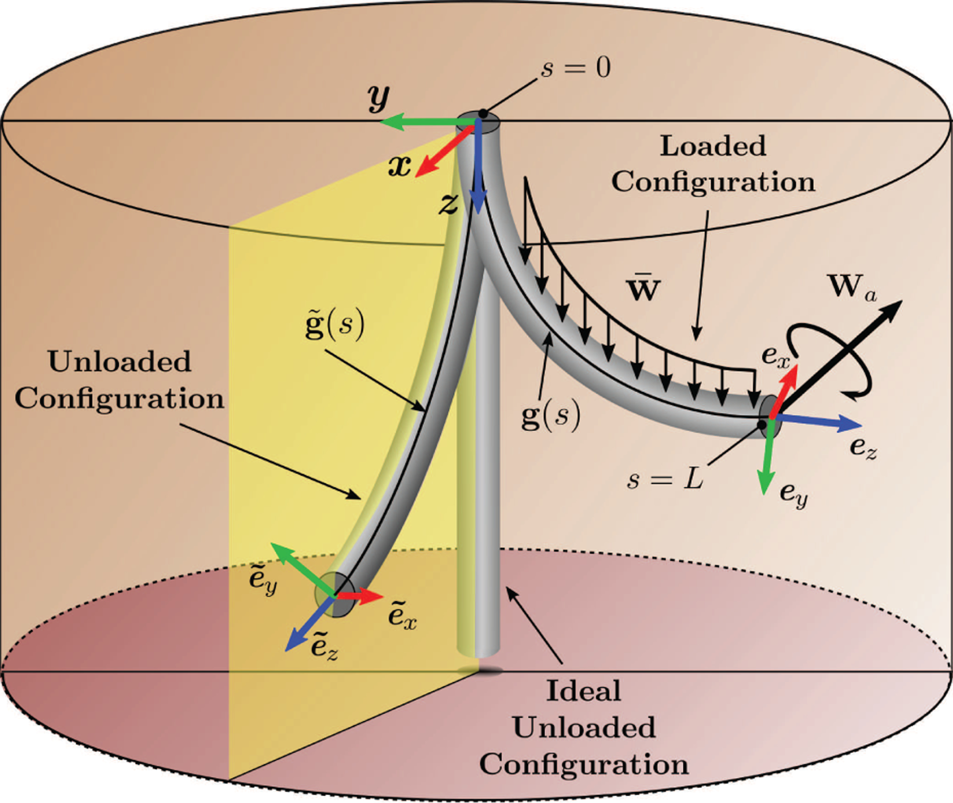
Soft continuum manipulator spatial configurations. In the ideal unloaded configuration the rod is perfectly straight. The unloaded configuration is pre-curved due to the existence of internal strain. The loaded configuration shows the rod bending under distributed and point loads.
Solving for the deflection of a generic soft continuum manipulator requires the knowledge of a subset of elements of y that is usually in the form of boundary conditions at the base (s = 0) and at the tip (s = l). These may be expressed in the form of Rucker and Webster (2011a), with the conditions at the base being
| (2) |
where yu represents a set of unknown elements of y and yk represents a known set of conditions at s = 0. Similarly, at the tip of the robot (s = l) the boundary conditions assume a more general form:
| (3) |
Equation (3) is in a generic form and may account for multiple connected continuum elements, each with different properties. Assuming a single continuum element whose spatial configuration can only be altered through the application of a follower wrench, as in Figure 1, the boundary conditions can be simplified to
| (4) |
where represents the effect from both a time-varying localized wrench which is a function of the joint parameters, wa(q), and an external constant wrench , e.g., gravity. By integrating Equations (1) using the boundary conditions (4) (i.e., solving the forward kinematic model), it is possible to estimate the deflection of the rod caused by a wrench applied at a specific location along its body. The solution of the forward kinematic model represents a geometric configuration in which all forces and moments applied on the body are in equilibrium. In order to accurately control tip motion with a soft structure, it is advantageous to apply a wrench in close proximity to the tip while constraining the base. A schematic representation of a soft continuum manipulator under these constraints is presented in Figure 1, and the associated boundary conditions can be expressed as
| (5) |
where it is assumed that the deformation of the soft body is caused exclusively by a wrench wa generated by the actuators and a tip load . The next section presents the static equations describing the equilibrium of the rod under the boundary conditions (5).
3. Kinematic modeling of a soft continuum manipulator under TFA
As introduced in Dill (1992), the centerline of an unloaded precurved rod can be described by an arc-length parametrized space curve , expressed with respect to a base coordinate frame attached at the proximal end of the rod. A frame is assigned to each point on the rod , with the orientation of the frame represented by a rotation matrix corresponding to the rotation of the base frame unit vectors . Under an external load, the parametric curve deflects to the curve p(s) and rotates to R(s). In this article, the homogeneous frames are assigned so that the z-axis of each frame is tangent to the curve. By differentiating the arc-length parametrized curve with respect to the parameter s, we obtain
| (6) |
where ez = R(s) k, and k = [0 0 1]T is the versor associated with the z-axis of the base coordinate frame. The continuous homogeneous transformation for the deflected rod may be defined as
| (7) |
A similar expression may also be defined for the initial state . The rotation of each point on the rod may be expressed in terms of a local curvature vector u(s), which can be found using the relationship (Murray et al., 1994)
| (8) |
where the operator ∨ denotes conversion of an element of to its corresponding element in . The curvature at each material point with respect to the initial state represents the local strains within the rod, and can be obtained using . The constitutive relationship between the curvature vector and internal moments, expressed in the local coordinate frame at s, is
| (9) |
where Mb(s) is the internal moment and K represents the stiffness matrix, defined as
| (10) |
where E is the Young’s modulus, Ix and Iy are the second moment of area of the tube cross-section, G is the shear modulus, and J is the polar moment of inertia of the tube cross-section. The equilibrium equations for the rod under external forces and moments were derived following a similar process to that described in Rucker et al. (2010). The resulting equations that govern the distribution of forces and moments along the rod can be expressed as
| (11) |
where Q(s) is the internal force, M(s) is the internal moment, f(s) represents the distributed force, m(s) represents the distributed moment along the rod, and Pδ(s − l) represents the concentrated force due to the tip concentrated mass at s = l. As the follower wrench is geometrically located at the tip of the manipulator, remaining always fixed with respect to the tip frame, it is convenient to express equations (11) with respect to the local coordinate frame. By recalling the derivative of vector v, expressed in moving coordinate frame in s, is v′ = u × v, than
| (12) |
where fb(s) = R(s)T f(s), Pb = R(s)T P, , and are the skew-symmetric matrices associated with the vectors ez and u, respectively. The effect of both the distributed force and of the weight at the tip can be easily estimated by knowing the orientation of the base and tip frames with respect to a global frame aligned with gravity:
| (13) |
where mt is the total concentrated mass at the tip and mb(s) is the distributed mass of the body and Rg represents the rotation of the base frame with respect to gravity. Substituting (9) in (12) and then solving for u′ yields
| (14) |
Equations (6), (9), (12), and (14) represent the model equations that need to be integrated from s = 0 to s = l in order to determine the state variables [p(s) R(s) u(s) Qb(s)] in the form expressed by (1) where y = [u(s) Qb(s)]. Boundary conditions for systems constrained at the base with TFA are expressed with respect to the proximal and distal ends of the soft body. Therefore, at s = 0, the position of the rod and the rotation of the attached frame at its base are defined respectively as
| (15) |
The boundary condition applied to the distal tip contains the discrete point wrench generated by the actuators, wa. The generic form for this boundary expression is
| (16) |
where wa|f and wa|m respectively represent the force and the moment components of the follower wrench expressed with respect to the tip frame.
4. Closed-loop control in task space
In this section, we propose a control scheme that can be applied to a soft manipulator actuated by a follower wrench in free space. During the motion, the body of the soft manipulator is acted upon by various forces and moments, including the TFA wrench, external distributed and point loads owing to gravity, and internal forces and moments within the elastic structure. The goal of the control scheme is to select and apply the tip follower wrench required to produce a static equilibrium corresponding to a desired manipulator pose.
In addition to achieving a desired pose, reducing oscillations enough to smoothly transition from one desired equilibrium state to another is challenging for soft continuum robots under TFA. These oscillations result primarily from two factors: (1) unmodeled dynamic effects that result from the acceleration of the body, and (2) the sensitivity of the manipulator pose to small changes in applied follower actuation, both of which are significant for soft compliant bodies. In addition, intrinsic model error due to inaccuracies in model parameters precludes accurate open-loop control, even in the case of very slow accelerations.
To address these challenges, the proposed quasi-static control scheme includes feedback from both the actuators and the tip pose. The actuator feedback is utilized to both regulate the follower load, in order to reduce any noise or overshoot in the input signal which can produce oscillations in the soft manipulator, and to compensate for non-linearities of the actuation system that can lead to incorrect tip wrench estimation, and thereby introduce kinematic model error. Pose feedback is required to compensate for modeling uncertainties and approximations in order to achieve the desired pose. In addition, we choose to command only small accelerations to the system in order to keep dynamic effects negligible. All three of these features work in conjunction to enable quasi-static path following.
A block diagram of the proposed control system is shown in Figure 2. The first feedback line senses the state of the actuator, whereas the second indicates the current configuration of the rod. Actuator feedback is used to estimate the current tip wrench to compute the forward kinematics model and the Jacobian matrix which maps changes in the wrench applied by the actuators to changes in the body configuration. The sensed configuration of the rod is used to calculate the error xerr between the current pose xobs and the desired input pose xdes. The pose error and actuator feedback are utilized within the linearized controller in order to solve for the desired actuator states q.
Fig. 2.
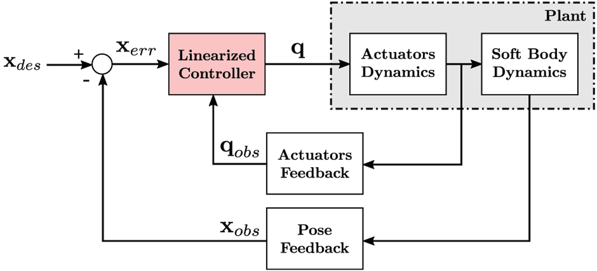
Block diagram representation of the proposed control system.
Figure 3 shows the linearized controller in detail. The control signal xcntr is obtained using a proportional–derivative feedback control scheme such as
| (17) |
where Kp and Kd are the proportional and derivative feedback gains and xerr is the pose error defined as
| (18) |
where xobs = [p(l) θe ψe γe]T and θe, ψe, γe represent the orientation of the tip with respect to the base frame. The control signal is then converted into change in tip wrench by using
| (19) |
where Rh(l) Cb is inverted with a least-squares method such as the Moore–Penrose pseudoinverse, indicated by † (Horn and Johnson, 1985), Cb is the body Jacobian matrix that maps changes in tip pose with changes in tip wrench as described in Rucker and Webster (2011a)), and Rh(l) represents the hybrid transformation between body frame and base frame. The hybrid transformation is required exclusively for the purpose of commanding desired tip trajectories expressed with respect to the base frame. This transformation can be removed if the application requires tip frame velocities to be commanded. A resolved motion rate approach (Whitney, 1969) is then used to obtain the required wrench to be produced at the tip.
Fig. 3.
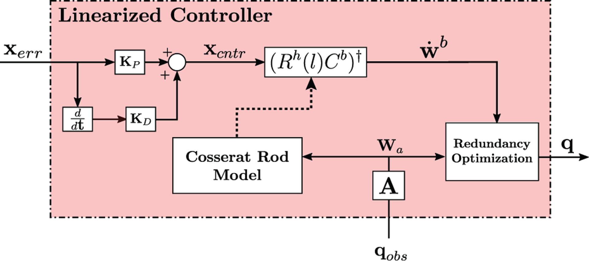
Block diagram detail of the linearized controller.
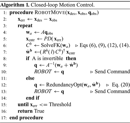
The DoF that can be controlled depend on the mapping between configuration parameters and generated wrench. In general, the wrench can be expressed as a system: wa,des(q) = Aq, where A is a matrix constituted of either linear or non-linear terms. If A is directly invertible, then the configuration parameters can be found analytically by q = A−1wa,des. If the actuator values are redundant or the matrix is not directly invertible, quadratic programming methods can be used to find the configuration parameters that minimize the norm squared of the error between the desired follower wrench to be applied by the actuators wa,des(q) and the applied follower wrench detected by the sensors wa, as
| (20) |
where qmin and qmax represent the lower and the upper limit of the actuator value, respectively. The pseudo-code of the closed-loop motion control algorithm is shown in Algorithm 1.
4.1. Elastic stability
As described previously, a change in the applied TFA wrench causes the manipulator to move into a new equilibrium configuration where internal body forces and moments are in balance with the applied wrench, as long as the robot remains in a stable static equilibrium. If the manipulator equilibrium configuration is close to an energy bifurcation point, small perturbations in the applied wrench can cause the manipulator to rapidly “snap” from one equilibrium configuration to another, spatially distant configuration (Gilbert et al., 2016; Till and Rucker, 2017). In order to prevent the manipulator from reaching an unstable region of the workspace, we analyze the effective stiffness matrix S, which relates to the manipulator’s ability to counteract the applied follower load:
| (21) |
A similar technique was implemented in Edelmann et al. (2017). The eigenvalues of S can be calculated from the compliance matrix Cb using the singular value decomposition:
| (22) |
Here (σ1 ⋯ σk) are the eigenvalues of the compliance matrix Cb. To prevent elastic instability, the eigenvalues of must all remain greater than zero, indicating an elastic restoring force which acts to counteract applied loads and maintain a stable equilibrium. Greater eigenvalues correspond to configurations that are more robust to external disturbances. Thus, our stability metric is defined as
| (23) |
which must remain greater than zero during operation to avoid elastic instabilities.
5. Soft continuum manipulator under TFA: example and application
The modeling and control framework described in Sections 3 and 4 respectively can be applied to any soft continuum manipulator under TFA and known tip load, such as soft robots actuated by tendons or magnetic fields. In order to experimentally assess the proposed approach, we apply it to control the motion of a specific soft continuum manipulator (called “the HydroJet”) that uses water jet propulsion to maneuver a tethered capsule within the stomach for upper gastrointestinal cancer screening (Campisano et al., 2017). Three miniature water-jet nozzles, spaced approximately 120° apart from each other along the diameter (Figure 4), are embedded in the endoscope tip. Pressurized water is carried through a multi-lumen catheter and laterally expelled through the nozzles. The resulting lateral reaction forces constitute a TFA and are used to generate bending in the structure, adjusting the pose of the endoscope camera. The number of controllable Cartesian DoFs depends on the mapping between joint space and generated wrenches. For this specific case, the three water-jets produce a resultant force in a plane perpendicular to the endoscopic tip axis (Figure 4). Owing to their physical arrangement, the water-jets are redundant, such that the robot can only carry out a 2-DoF task (variables ϑ and φ as shown in Figure 7). Thus, the achievable 3D workspace for the manipulator forms approximately an hemisphere with center at the base frame. This specific soft robot morphology, owing to its low-stiffness body and high sensitivity to both unmodeled effects and changes in actuation, constitutes one of the clearest examples of tip follower actuated device to assess the performance of the proposed control algorithm.
Fig. 4.
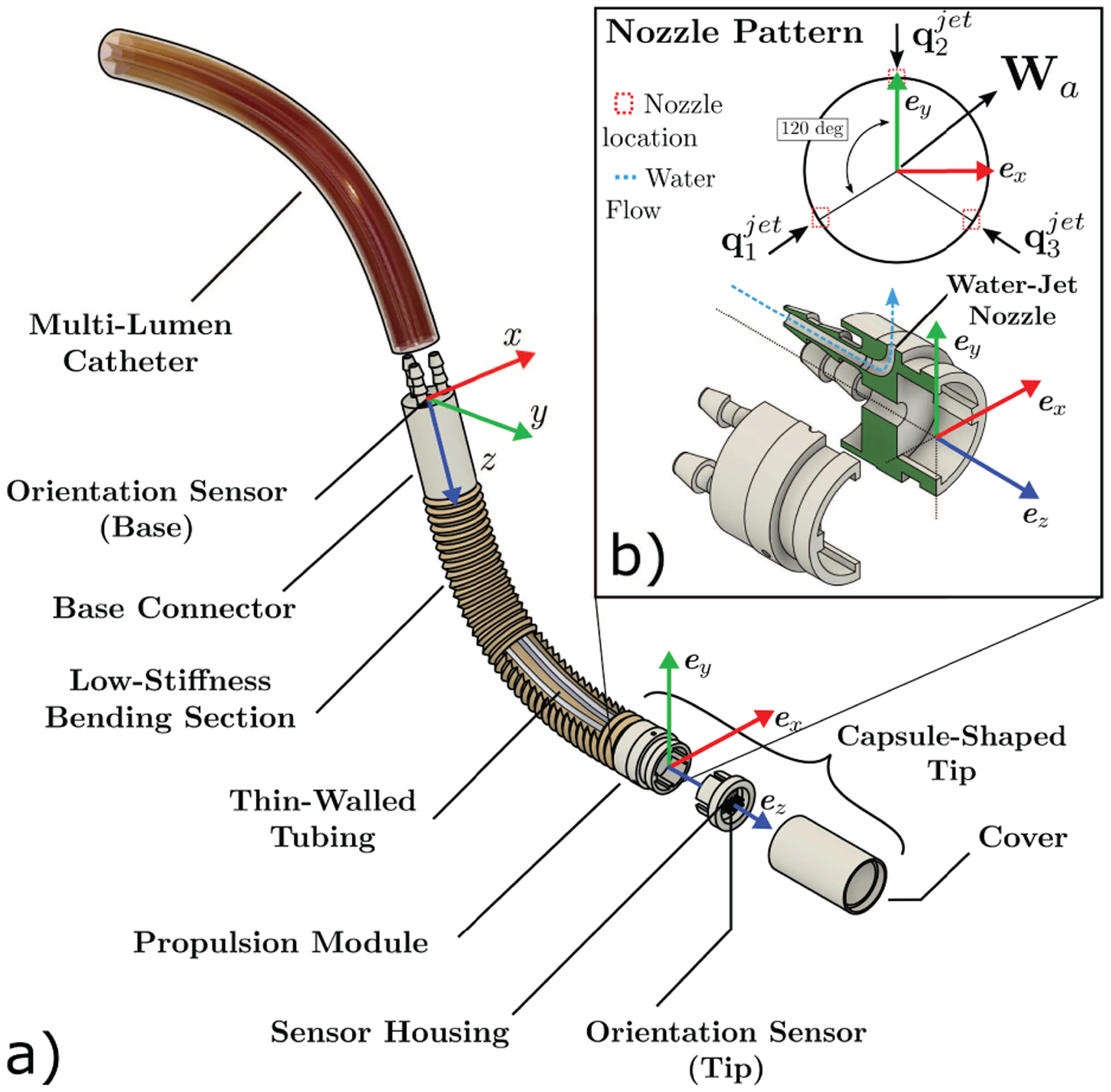
The HydroJet, a soft continuum endoscope manipulated via TFA that is used to experimentally validate the proposed control method, showing: (a) exploded view of the continuum endoscope; and (b) a detailed view of the locations of the water jet nozzles with respect to the tip frame.
Fig. 7.

The HydroJet’s workspace: the manipulator’s tip can be maneuvered with two DoFs by commanding ϑ and φ.
5.1. Bending section design and manufacturing
To work as an effective endoscopic device for upper gastrointestinal inspection, the HydroJet is required to achieve high bending angles within a relatively small workspace. To facilitate greater range of motion, a low stiffness bending section was developed and integrated between the capsule-shaped tip and the multi-lumen catheter, as shown in Figure 4. The low stiffness bending section is composed of two main parts: (1) three thin-walled tubes (35D Pebax 6fr 0.008” wall, Apollo Medical Extrusions), responsible for carrying pressurized water from the multi-lumen catheter to the water jet nozzles; and (2) a custom elastomeric bellows for setting the stiffness of the soft body and for constraining the internal tubes to prevent their relative motion or buckling. The internal tubes were twisted around themselves to achieve a relatively even stiffness in all bending directions. The bellows was manufactured of soft silicone (Ecoflex 00-30, Smooth-On, USA) through injection molding and has a maximum and minimum outer diameter of 10.5 and 6.5 mm, respectively, with wall thickness of 0.7 mm (under zero strain). The internal tubing and bellows were assembled as shown in Figure 4. The resulting body allows bending relative to the base connector if actuated under TFA.
6. Experimental methods
6.1. HydroJet system testbed
The testbed was assembled as illustrated in Figure 5. The capsule-shaped tip components (propulsion module, sensor housing, cover) were made from a durable plastic (Clear resin, FormLabs, Sommerville, MA, USA) through rapid prototyping. The tip outer diameter and length are 9.80 and 28 mm, respectively. A 6-DoF electromagnetic sensor (Northern Digital Inc., Canada) was integrated within the capsule and aligned to the capsule frame. The wire of the electromagnetic sensor runs through the soft-elastomer bellows together with the three single-lumen water lines connecting the tip to the base connector (Figure 4). The base was connected to three solenoid water valves (A352273, Asco Numatics, USA) using standard hydraulic tubing (1/16” ID × 1/8”OD Tygon E-3603, Cole-Parmer, USA). The flow rate of each of the water lines was measured using independent flow sensors (710-V00A Atrato ultrasonic flow sensor, Titan Enterprises Ltd., UK). The base connector was held in the desired orientation using a custom 3D-printed holder attached to a manual rotation stage (PR01/M, Thor-labs, USA). The assembly was secured in place through attachment to an aluminum frame (Rexroth, Bosch, Germany). A second 6-DoF electromagnetic sensor (EM) was attached to the base holder to sense the orientation of this frame as well. Two webcams (C930e, Logitech, Switzerland) were placed in the positions shown in Figure 5 to visually observe the motion during the various experiments from front and top view.
Fig. 5.
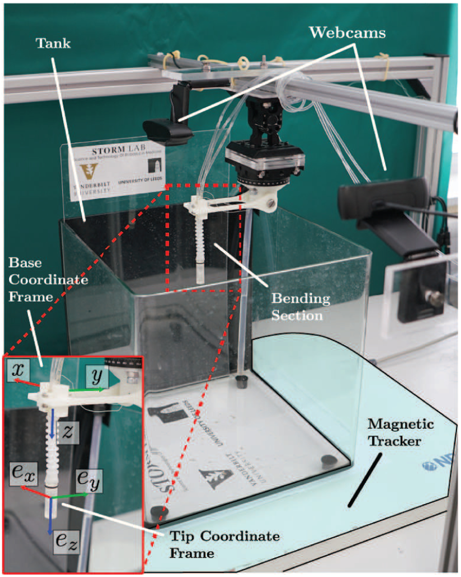
Experimental setup consisting of a magnetic tracker, two webcams, and the HydroJet. At the bottom left corner, the base and tip reference frames are shown.
6.2. Calibration
The kinematic model was calibrated through optimizing the set of parameters listed in Table 1 to best fit experimental data. The boundary conditions for the HydroJet are described as follows: at s = 0, position is considered to be zero and the orientation is captured via the electromagnetic sensor within the base connector. At s = l, the three components of the internal moment must be zero and the force expressed in tip frame is defined by the flow rates of the three water-jets. Considering that the water nozzles are spaced approximately 120° apart around the diameter of the capsule (Figure 4), the net applied wrench in the body frame acting on the tip of the manipulator due to the water-jet forces is defined as
| (24) |
where q1, q2, and q3 are the three applied forces due to the water jets and δα, δβ, δγ represent the deviation in alignment of the actual jet force with the intended direction due to manufacturing imperfections (Figure 6). With the applied wrench wa expressed in the tip frame, we can express the boundary conditions at s = l as
| (25) |
Table 1.
Calibrated values of model parameters.
| Parameter | Value |
|---|---|
| 243 mN | |
| 224 mN | |
| 244 mN | |
| GJ | 2.23 × 10⁻⁴ N m |
| EI | 6.01 × 10⁻⁴ N m |
| ux | 0.034 m−1 |
| uy | 0.88 m−1 |
| Ain | 1.13 × 10⁻⁶ m2 |
| Aout | 3.84 × 10⁻⁷ m2 |
| L | 0.09 m |
| mt | 2.58 g |
| δα | 0.12 rad |
| δβ | 0.06 rad |
| δγ | −0.08 rad |
Fig. 6.
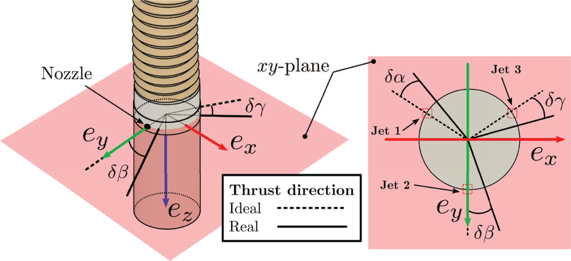
Water-jet actuation system: the force vectors generated by the jets lay on the tip xy-plane and are ideally spaced 120° from each other. The parameters δα, δβ, δγ describe the jets mis-alignment, with respect to the ideal case, due to manufacturing imperfections.
For the purpose of modeling, the bellow and the internal water lines were considered as a single element having a cylindrical shape with inner diameter of 6 mm, outer diameter of 8 mm, and a length of 90 mm. The soft body is considered massless (i.e., mb = 0) and the mass of the capsule mt (2.58 g) is used in Equation (13) to compute the force due to gravity in tip frame. This assumption is reasonable for this particular robot design, as the concentrated mass at the tip has a much greater influence on its motion than the smaller mass distributed along the length.
The force exerted on the capsule from the water jets was calculated using the thrust equation:
| (26) |
where is the mass flow rate through the jet cavity, and vout and vin are the outlet and inlet velocity that relate to the nozzles external and internal areas through vinAin = voutAout. The EM sensor was aligned to the tip frame by placing the tip of the soft manipulator in a calibration box with a known position with respect to the global frame. This calibration allowed the alignment of the jets with respect to the EM frame. A similar calibration procedure was performed for the base orientation sensor to align its frame with respect to the base holder. The orientation of both frames with respect to the global frame is shown in Figure 5.
The calibration of the soft body parameters was done experimentally by finding the parameter vector that minimizes the objective function representing the rotation error between the estimated and experimentally observed orientations over a set of 40 random jet force combinations around the workspace:
| (27) |
where hm = a+bi+cj+dk represents the quaternion associated with the rotation computed by solving the forward kinematics with inputs qi and parameter vector ζ, hi represents the quaternion associated with the measured experimental rotation from the EM sensor, and 〈·〉 represents the scalar product of two vectors. The parameter vector is constituted by ζ = [ux uy G E δα δβ δγ]T. Results of the calibration are summarized in Table 1.
7. Experimental validation
To validate the proposed control scheme for soft continuum manipulators under TFA and external loading, two sets of experiments were performed, each using both open-loop and closed-loop schemes. The first experiment consisted of controlling manipulator tip orientations along a spiral path while having the z-axis of the base connector aligned with the direction of gravity, as shown in Figure 8(a). In the second experiment, the base connector was rotated by 30 degrees around its local x-axis, and the same spiral path was commanded to the manipulator. Owing to this change in the alignment with respect to gravity, the forces and moments along the soft body under static equilibrium result in an initial shape (wa = 0) that bends toward the direction of gravity (Figure 8(b)). Both of these experimental setup angles fall within the expected range of deployment angles for the intended application of gastroscopy.
Fig. 8.
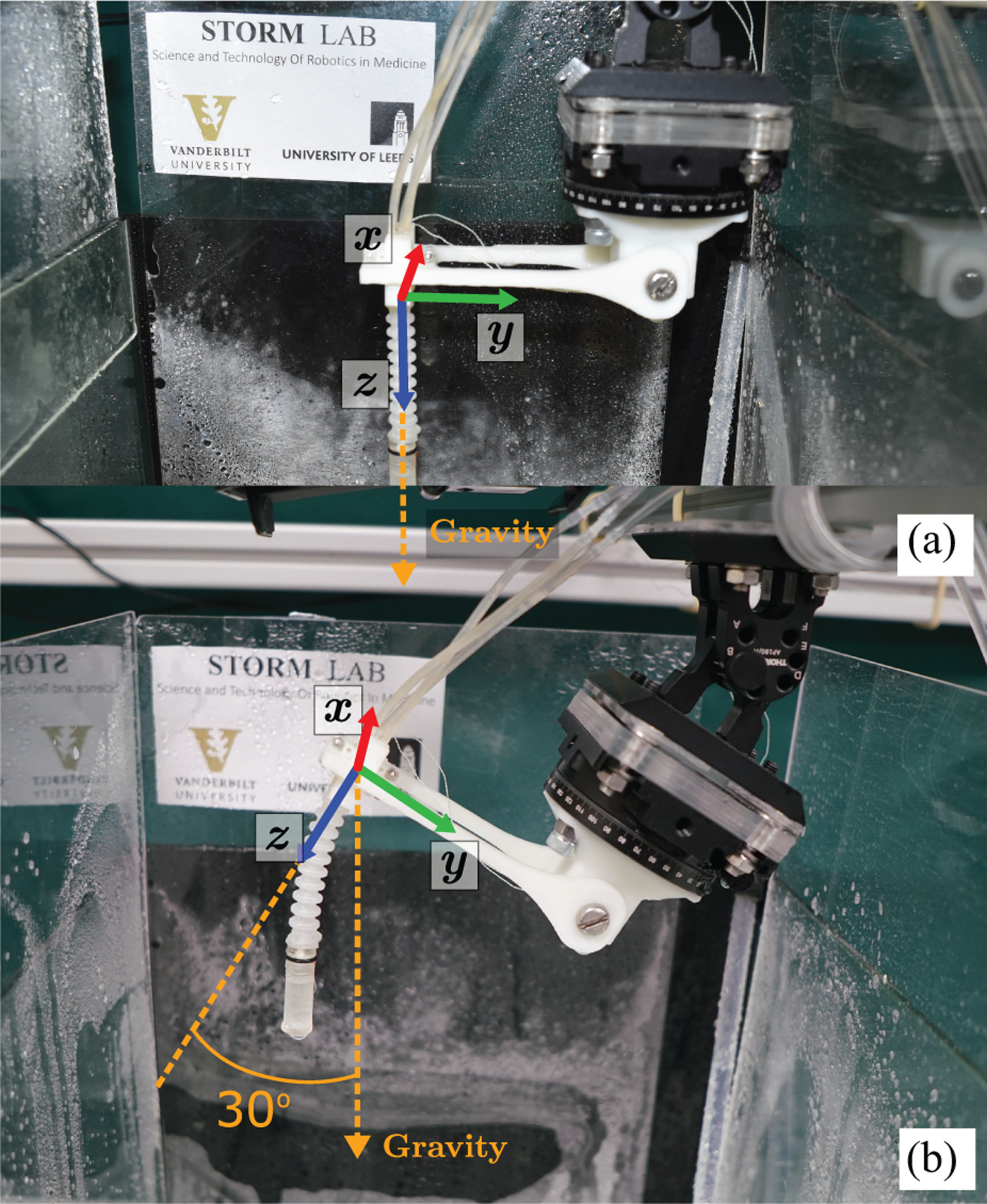
Starting configurations for the path-following trials: (a) initially straight and (b) initially bent with respect to the direction of the gravity vector.
7.1. Path generation
The spiral path commanded to the robot was expressed in terms of two angles as xdes(t) = [ϑdes(t) φdes(t)]T, with respect to the base frame, as shown in Figure 7. The time-varying path was defined according to
| (28) |
where ς = 0.1 rad s−1 and ε = 0.8 rad s−1, which results in a desired tip speed of 1.61 rad s−1. The tip speed is relatively low to limit the effects of both body dynamics and of non-linearities of the actuation system. The path was set to be completed in 600 s. We choose this relatively slow speed to be consistent with the quasi-static modeling assumption; however, it is still fast enough to perform the intended task of gastroscopy in the time frame of about 12 minutes typically required to complete the procedure (Miller et al., 2019).
7.2. Software implementation
The control system was implemented in a custom C++ Linux program running on a 3.7 GHz Intel Core i7-8700K processor with 16 GB RAM using ROS Kinetic. The model equations (6), (9), (12), and (14) were integrated numerically, beginning with the tip pose and integrating backward toward the base. The state Jacobians were integrated with an eighth-order Runge–Kutta method (Ketcheson and bin Waheed, 2014). Altogether, the program is capable of solving the rod equations and calculating the necessary Jacobians within 10 ms. To provide values for qobs and xobs, the flow sensors and electromagnetic sensors were sampled at 100 Hz.
7.3. Open-loop testing
The open-loop water-jet forces for a given desired orientation were computed by subsequent minimization of the tip orientation error using the Jacobian matrix (19). In this test, the actuator feedback is utilized to compute both the estimated pose of the manipulator and the Jacobian matrix, without including any pose feedback. The desired orientation (ϑdes, φdes) is converted into the equivalent representation in Euler angles (pitch and yaw) by using an axis angle transformation. The orientation error is then obtained by subtracting estimated pitch and yaw from the desired values and the water-jet forces updated accordingly. The test was considered complete if ϑ = 1.04 rad and φ = 14 rad, or was aborted if the amplitude of the oscillations of the tip during the transitions between two consecutive commanded states were higher than 0.5 rad.
7.4. Closed-loop testing
Closed-loop testing was performed using the control scheme described in Section 4 utilizing both actuators and tip pose feedback. Real-time computation of the water-jet forces was performed based on the orientation error between the desired values and those measured from the embedded EM sensor in the tip frame. The proportional and differential gains were manually tuned to provide good performance throughout the robot workspace and reduce oscillations during the transition between states. Test completion criteria were the same as for the open-loop test case.
7.5. Path-following results: initially straight configuration
As mentioned previously, the first set of experiments were performed with the base aligned with gravity, i.e., with the manipulator body starting in a nearly straight configuration pointing downward (Figure 8(a)). Five repeat path-following trials were performed for the open-loop and closed-loop control configurations. Figure 9 presents the results from single path-following trials using the open-loop and closed-loop control schemes. The orientation error is defined as the Euclidean norm of the difference between desired tip orientation and measured tip orientation obtained from the EM sensor located at the tip. The points along the path where the norm of the orientation error exceed the 90th percentile of its distribution (indicated as σ in Figure 9) are highlighted in red. These points represent areas of the path where the system shows a slower convergence to the desired orientation with increased oscillation. The root-mean-square (RMS) open-loop and closed-loop orientation error was 0.09 and 0.03 rad, respectively, indicating significant improvement in path-following accuracy in the closed-loop case over the open-loop case. It is also evident from Figure 9 that the closed-loop performance is consistent along the entire path, whereas the open-loop accuracy degrades and oscillations increase toward the end of the path, corresponding to larger pitch angles. In addition, the desired open-loop path was not completed owing to excessive oscillations (ϑ > 0.5 rad).
Fig. 9.
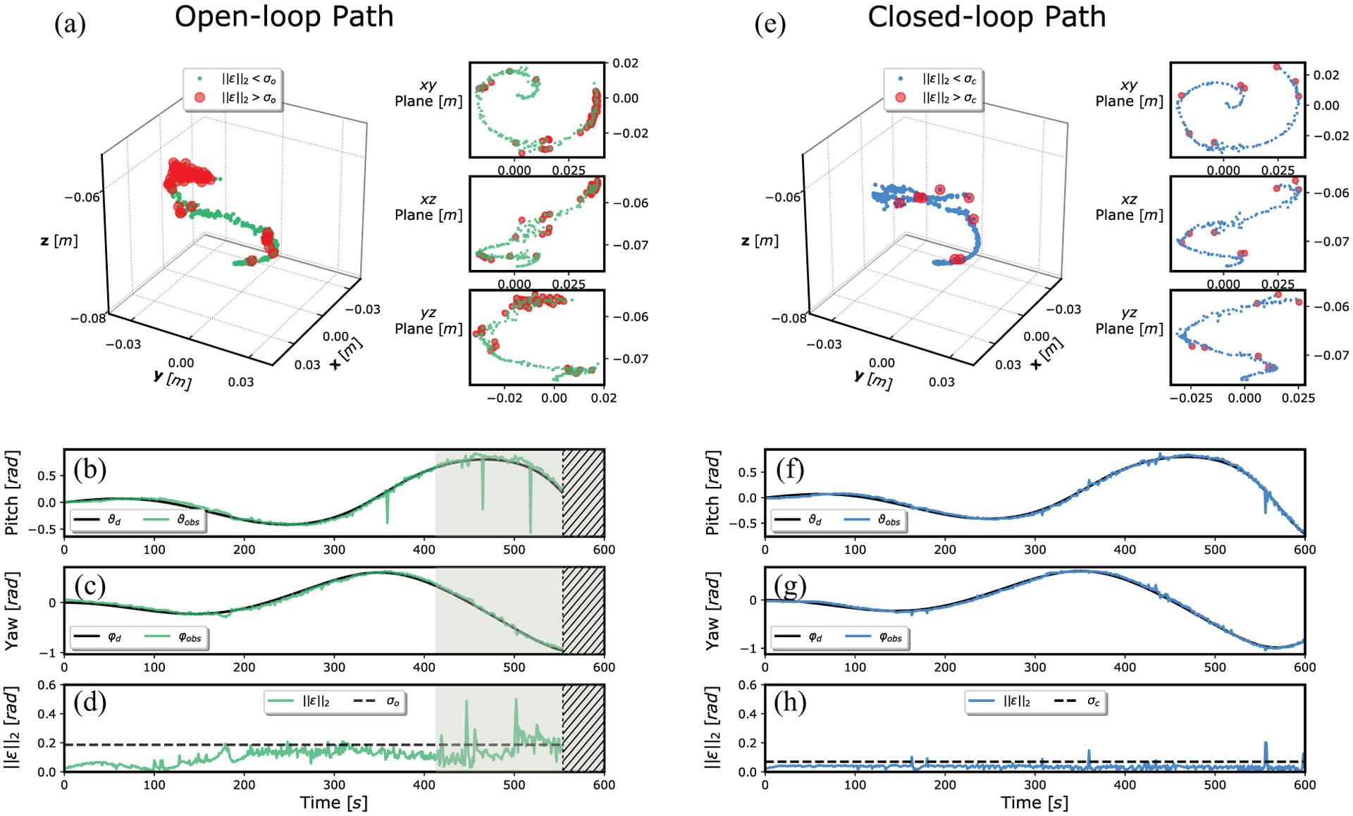
Path-following results for open-loop (left column) and closed-loop (right column) strategies applied to the HydroJet soft continuum manipulator under TFA with the base oriented parallel to Earth’s surface, such that gravity acts along the z-axis of the robot at its base (0° base angle). Graphs (a) and (e) show a 3D view of the measured path followed by the capsule-shaped tip and its projection on xy, xz, and yz planes for open-loop and closed-loop, respectively; the red dots indicate the locations of points on the path where the norm of the error was greater than a pre-defined threshold (σ = 90th percentile). The desired (black line) and measured (colored lines) paths for pitch and yaw angles are shown in (b) and (c) for the open-loop case, and in (f) and (g) for the closed-loop case. Finally, the norm of the error is presented for open-loop and closed-loop trials in (d) and (h), respectively; the threshold (dashed line) representing the 90th percentile, the region where the tip oscillations become large (shaded region), and areas where the trial was aborted due to excessive oscillations (ϑ > 0.5 rad (shaded region with hatch) are shown.
7.6. Path-following results: initially bent configuration
The second set of experiments demonstrate motion controllability of the soft manipulator tip along a desired path starting from an initially bent manipulator configuration, induced via a 30° rotation of the base frame around its local x-axis (Figure 8(b)), such that it is no longer aligned with the direction of gravity. The same testing protocol described in Section 7.5 was implemented to again assess performance under open-loop and closed-loop control schemes. As in the previous set of experiments, five repeat path-following trials were performed for the open-loop and closed-loop control schemes, respectively. Path-following results are presented in Figure 10. The RMS open-loop and closed-loop orientation error was 0.18 and 0.035 rad, respectively. The open-loop path again shows a greater path-following error than the closed-loop, with accuracy and stability being largely dependent on ϑdes; again, for the open-loop case, this results in an incomplete test owing to excessive oscillations (ϑ > 0.5 rad). In contrast, under closed-loop control, path-following accuracy is improved and the oscillation of the manipulator along the path is maintained across the range of desired orientations.
Fig. 10.
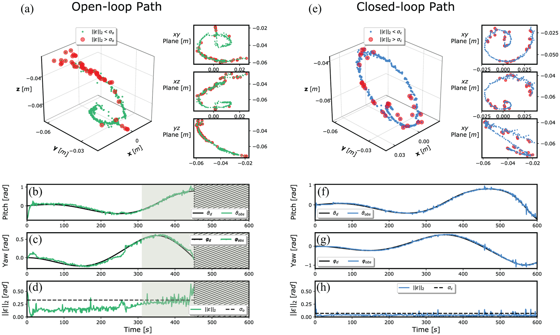
Path-following results for open-loop (left column) and closed-loop (right column) strategies applied to the HydroJet soft continuum manipulator under TFA with the base in a bent configuration with respect to gravity (30° base angle). Graphs (a) and (e) show a 3D view of the measured path followed by the capsule-shaped tip and its projection on xy, xz, and yz planes for open-loop and closed-loop, respectively; the red dots indicate the locations of points on the path where the norm of the error was greater than a pre-defined threshold (σ = 90th percentile). The desired (black line) and measured (colored lines) paths for pitch and yaw angles are shown in (b) and (c) for the open-loop case, and in (f) and (g) for the closed-loop case. Finally, the norm of the error is presented for open-loop and closed-loop trials in (d) and (h), respectively; the threshold (dashed line) representing the 90th percentile, the region where the tip oscillations become large (shaded region), and areas where the trial was aborted due to excessive oscillations (ϑ > 0.5 rad (shaded region with hatch) are shown.
7.7. Repeated trials
Results indicating the median, interquartile range, maximum and minimum values for each repeat trial under the tested configuration are summarized in Figure 11. To allow comparison between experimental configurations, the mean error distribution has also been presented for each control scheme and base orientation combination. For the open-loop case, large variability is evident across trial repeats, and the median error values range from 0.096 to 0.116 rad for the initially straight configuration and from 0.181 to 0.208 rad for the initially bent configuration (corresponding to μ±sd values of 0.115±0.072 rad and 0.228±0.106 rad, respectively, when averaged over all repeats). The relatively large standard deviations are in agreement with the large error distribution seen for all open-loop trials, highlighting high oscillations in the system. The influence of gravity on the soft manipulator under the initially bent configuration increases the median of the error from 0.106 to 0.197 rad when compared with the initially straight configuration, representing a increase of 85.5%.
Fig. 11.
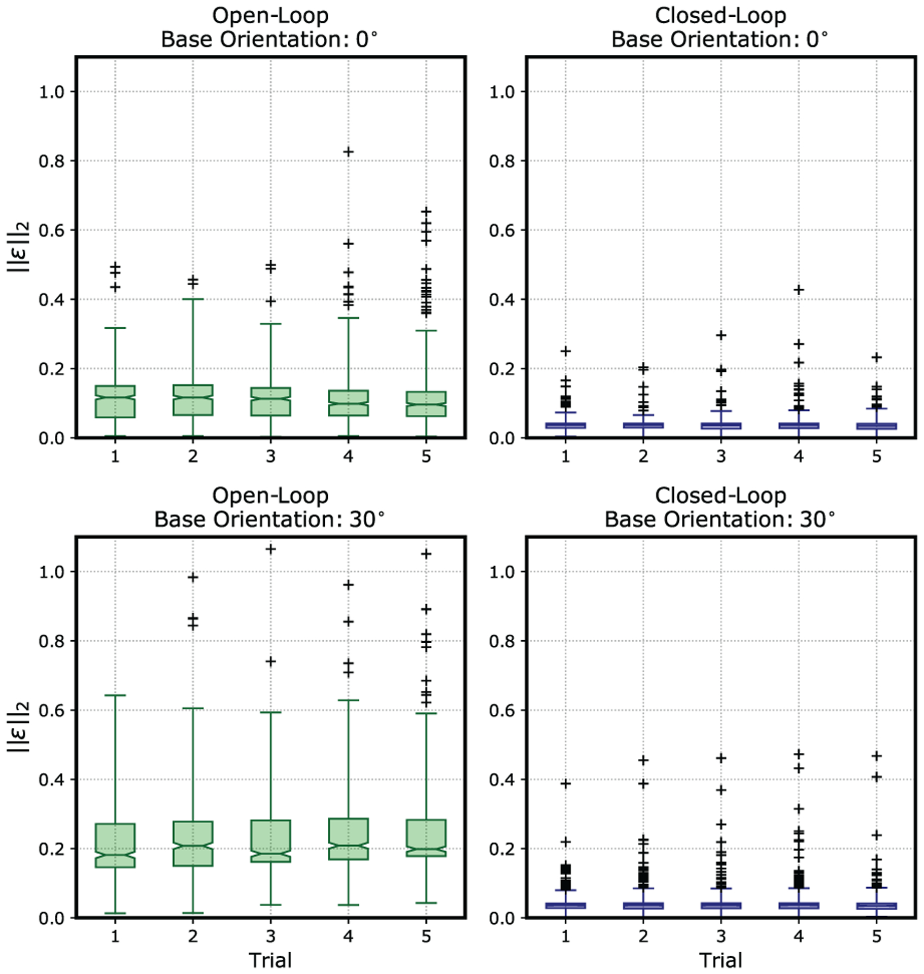
Box plot showing error distribution and variability over the five tests performed for each set of experiments for both closed loop and open loop, in the flat and pre-bent initial configuration.
In comparison, the closed-loop scheme generates narrow error distributions and shows minimum variability of the median, ranging from 0.034 to 0.037 rad for the initially straight configuration and from 0.035 to 0.037 rad for the initially bent configuration (corresponding to μ±sd values of 0.035 ± 0.019 rad and 0.039 ± 0.032 rad, respectively, when averaged over all repeats). The influence of gravity in the initially bent configuration increases the median error from 0.0359 to 0.0360 rad, representing an increase of 0.20%.
7.8. Stability analysis
To demonstrate that both commanded paths utilized in previous experiments are within an elastically stable workspace for the manipulator, in this section we evaluate the stability measure σc for the prototype manipulator described in Section 5. The workspace is evaluated across a discretized range of jet forces spanning the achievable actuator range (q < qmax), resulting in an input data set of 3,000 actuation combinations. For both initial robot configurations (initially straight and initially bent), the stability measure is calculated by evaluating the compliance matrix at each single pose within the range of inputs. Results are shown in Figure 12 for the initially straight configuration and in Figure 13 for the initially bent configuration. In both plots, the value of the smallest eigenvalue of the S matrix remains positive throughout the entire actuation space, confirming the elastic stability of the manipulator during both previous path-following tasks.
Fig. 12.

Stability test of the manipulator workspace for the initially straight case. The eigenvalues of the stiffness matrix remain positive throughout the entire actuation space.
Fig. 13.
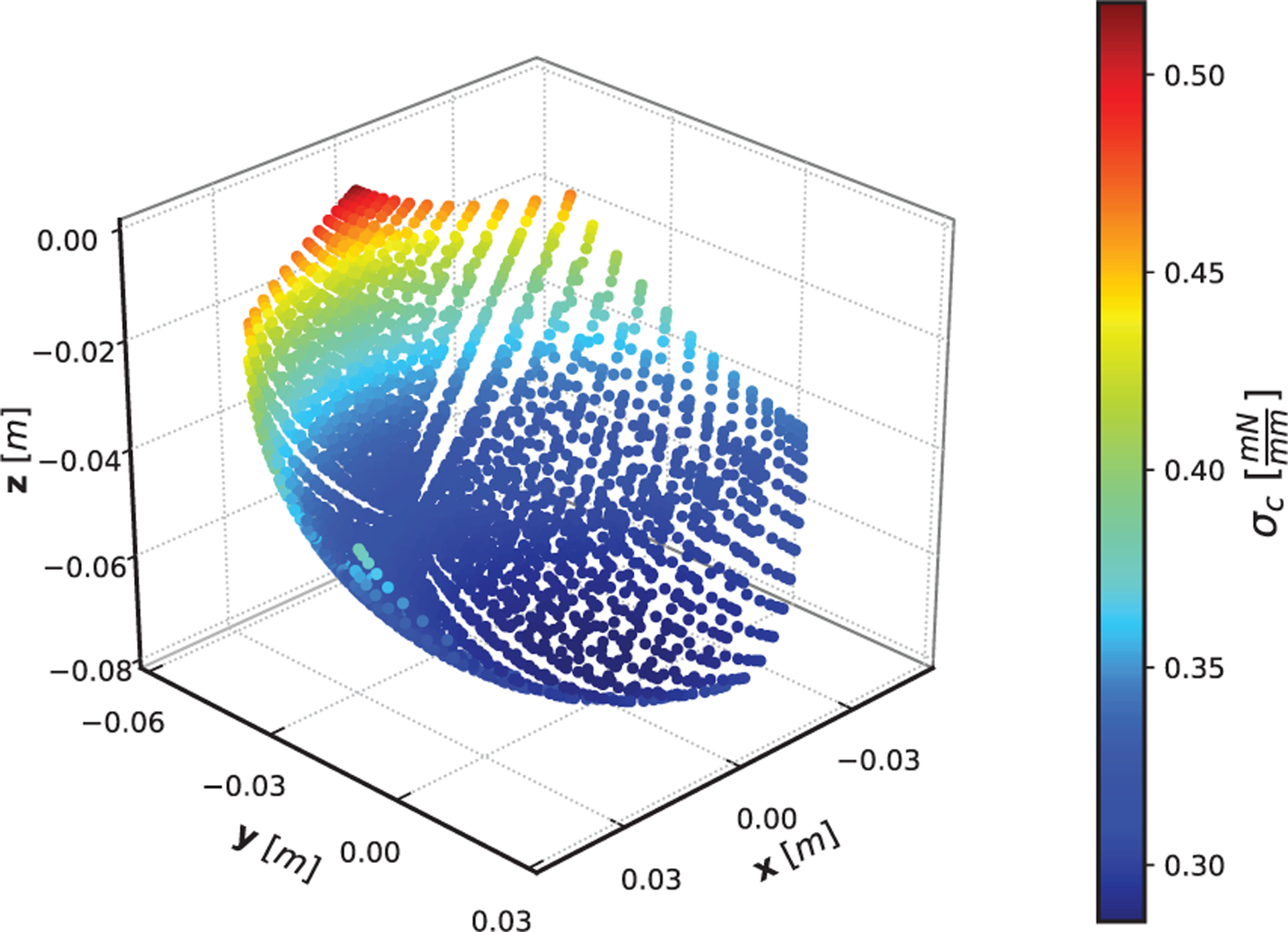
Stability test of the manipulator workspace for the initially bent case. The effective stiffness of the manipulator is not symmetric due to the rotation of the base frame. Similar to the initially straight case, the eigenvalues of the stiffness matrix remain positive throughout the entire actuation space.
8. Discussion
The results suggest that the Cosserat rod equations can be successfully implemented to model and control a soft continuum manipulator under TFA in free space. The presented closed-loop scheme improves the tracking capability when compared to the open-loop test cases, as evidenced by the large reduction in orientation error when moving from the open-loop to the closed-loop case (from 0.096 to 0.034 rad for 0° base angle and from 0.181 to 0.035 rad for 30° base angle). The open-loop oscillations are particularly prominent at larger pitch angles, demonstrating the importance of using feedback to compensate model and parameter inaccuracies intrinsic to soft manipulators under TFA. In particular, the use of a closed-loop scheme is important when considering possible clinical applications that require accurate and repeatable poses, such as camera positioning or autonomous screening. Thus, future work that focuses on adding a human in the loop through teleoperation would be interesting from both a clinical and technical standpoint.
The closed-loop scheme presented requires measurement of the tip orientation, which in the presented case was achieved using EM sensors. The idea of using orientation feedback enables control using inexpensive feedback sensors. For example, orientations can also be tracked via lower-cost sensors, such as inertial measurement units (IMUs), embedded into the base and tip of the manipulator, without significantly reducing accuracy (Madgwick et al., 2011). This is relevant for clinical applications, where pairing cheap manufacturing of soft continuum bodies with inexpensive sensors enables the whole system to be used as a low-cost disposable medical device.
The model and control strategy can be generalized for other applications to account for, for example, a full 6-DoF wrench applied at any location along the body or a connection of multiple soft bodies with different stiffness characteristics. In addition, the Cosserat rod framework has been used in other types of continuum robots for contact detection with external bodies (Mahvash and Dupont, 2010) and/or implementation of state constraints (Tully et al., 2012), suggesting these goals should also be possible for soft manipulators under TFA. Furthermore, in this work we have not considered external disturbance loads owing to the environment. In the proposed application of gastroscopy, this is a reasonable assumption, as the HydroJet system is intended to operate within the open cavity of the stomach for the purposes of inspection only, which does not require significant interaction with the surrounding environment. In this type of scenario, the ability to accurately control the device in free space can enable the user to avoid contact with the tissue in order to maintain model accuracy. Still, the ability to compensate for unknown external loads using this method remains an area for future work.
Lastly, the framework presented in this article has its limitations for applications that require fast transitions between equilibrium states. In that case the non-linear dynamics of the soft body may result in excessive oscillations, even under the presented closed-loop scheme, rendering the quasi-static model described in this article insufficient. A possible solution was presented in Rucker and Webster (2011b), where a Cosserat-rod-based dynamic model was developed for a continuum robot which might be extended for the soft manipulator case. A real-time implementation of the Cosserat rod dynamic model for the soft manipulator case would enable better control schemes, particularly in the case of fast motions of the manipulator. Accurate models for both soft body and actuators dynamics, will also enable full dynamic stability analysis of the control scheme proposed in this article. Another possible solution to reduce oscillations while keeping the static model is to improve the design of the hydraulic actuation system in order to obtain a more nearly linear relationship between current and flow rate. This would reduce hysteresis in the actuation system, thus enabling even more precise control of the applied wrench.
9. Conclusions
This article has presented a method for employing real-time control of the equilibrium configurations of soft continuum manipulators actuated via a follower wrench and experiencing external loading. The proposed method couples Cosserat-rod-based modeling with integrated sensing and efficient numerical determination of the Jacobian matrix at each time step to deliver a practically viable, closed-loop control system for application to soft continuum manipulators. Closed-loop performance was demonstrated on a soft continuum endoscope (the HydroJet), and was shown to be effective in reducing orientation error and increasing system stability even under the influence of gravity. The stable closed-loop path following as demonstrated has the potential to enable semi- and fully autonomous manipulation tasks in the next generation of soft continuum robots under TFA.
Acknowledgment
The authors would like to thank the Vanderbilt Institute for Surgery and Engineering (ViSE) for their support of our work and utilization of space.
Funding
Research reported in this article was supported by the Royal Society (grant number CH160052), by the Engineering and Physical Sciences Research Council (EPSRC; grant number EP/P027938/1), and by the National Institute of Biomedical Imaging and Bioengineering (award number R01EB018992). Any opinions, findings and conclusions, or recommendations expressed in this article are those of the authors and do not necessarily reflect the views of the Royal Society, EPSRC, or NIH.
References
- Bajo A and Simaan N (2012) Kinematics-based detection and localization of contacts along multisegment continuum robots. IEEE Transactions on Robotics 28(2): 291–302. [Google Scholar]
- Calisti M, Giorelli M, Levy G, et al. (2011) An octopus-bioinspired solution to movement and manipulation for soft robots. Bioinspiration and Biomimetics 6(3): 036002. [DOI] [PubMed] [Google Scholar]
- Campisano F, Gramuglia F, Dawson IR, et al. (2017) Gastric cancer screening in low-income countries: System design, fabrication, and analysis for an ultralow-cost endoscopy procedure. IEEE Robotics and Automation Magazine 24(2): 73–81. [DOI] [PMC free article] [PubMed] [Google Scholar]
- Chirikjian GS and Burdick JW (1995) The kinematics of hyper-redundant robot locomotion. IEEE Transactions on Robotics and Automation 11(6): 781–793. [Google Scholar]
- Deimel R and Brock O (2013) A compliant hand based on a novel pneumatic actuator. In: 2013 IEEE International Conference on Robotics and Automation (ICRA). IEEE, pp. 2047–2053. [Google Scholar]
- Dill EH (1992) Kirchhoff’s theory of rods. Archive for History of Exact Sciences 44(1): 1–23. [Google Scholar]
- Dupont PE, Lock J, Itkowitz B and Butler E (2010) Design and control of concentric-tube robots. IEEE Transactions on Robotics 26(2): 209–225. [DOI] [PMC free article] [PubMed] [Google Scholar]
- Edelmann J, Petruska AJ and Nelson BJ (2017) Magnetic control of continuum devices. The International Journal of Robotics Research 36(1): 68–85. [Google Scholar]
- Fallahi B, Rossa C, Sloboda RS, Usmani N and Tavakoli M (2016) Sliding-based switching control for image-guided needle steering in soft tissue. IEEE Robotics and Automation Letters 1(2): 860–867. [Google Scholar]
- Garriga-Casanovas A and Rodriguez y Baena F (2018) Complete follow-the-leader kinematics using concentric tube robots. The International Journal of Robotics Research 37(1): 197–222. [Google Scholar]
- Gilbert HB, Rucker DC and Webster RJ III (2016) Concentric tube robots: The state of the art and future directions. In: Robotics Research. Berlin: Springer, pp. 253–269. [Google Scholar]
- Giri N and Walker I (2011) Continuum robots and underactuated grasping. Mechanical Sciences 2(1): 51–58. [Google Scholar]
- Horn RA and Johnson CR (1985) Matrix Analysis. Cambridge: Cambridge University Press. [Google Scholar]
- Jones BA, Gray RL and Turlapati K (2009) Three dimensional statics for continuum robotics. In: IEEE/RSJ International Conference on Intelligent Robots and Systems, 2009 (IROS 2009). IEEE, pp. 2659–2664. [Google Scholar]
- Ketcheson D and bin Waheed U (2014) A comparison of high-order explicit Runge–Kutta, extrapolation, and deferred correction methods in serial and parallel. Communications in Applied Mathematics and Computational Science 9(2): 175–200. [Google Scholar]
- Khadem M, Rossa C, Sloboda RS, Usmani N and Tavakoli M (2016) Ultrasound-guided model predictive control of needle steering in biological tissue. Journal of Medical Robotics Research 1(01): 1640007. [Google Scholar]
- Kratchman LB, Bruns TL, Abbott JJ and Webster RJ (2017) Guiding elastic rods with a robot-manipulated magnet for medical applications. IEEE Transactions on Robotics 33(1): 227–233. [DOI] [PMC free article] [PubMed] [Google Scholar]
- Largilliere F, Verona V, Coevoet E, Sanz-Lopez M, Dequidt J and Duriez C (2015) Real-time control of soft-robots using asynchronous finite element modeling. In: 2015 IEEE International Conference on Robotics and Automation (ICRA). IEEE, pp. 2550–2555. [Google Scholar]
- Madgwick SO, Harrison AJ and Vaidyanathan R (2011) Estimation of IMU and MARG orientation using a gradient descent algorithm. In: 2011 IEEE International Conference on Rehabilitation Robotics (ICORR). IEEE, pp. 1–7. [DOI] [PubMed] [Google Scholar]
- Mahvash M and Dupont PE (2010) Stiffness control of a continuum manipulator in contact with a soft environment. In: Proceedings of the IEEE/RSJ International Conference on Intelligent Robots and Systems, p. 863. [DOI] [PMC free article] [PubMed] [Google Scholar]
- Mahvash M and Dupont PE (2011) Stiffness control of surgical continuum manipulators. IEEE Transactions on Robotics 27(2): 334–345. [DOI] [PMC free article] [PubMed] [Google Scholar]
- Marchese AD, Komorowski K, Onal CD and Rus D (2014) Design and control of a soft and continuously deformable 2D robotic manipulation system. In: 2014 IEEE International Conference on Robotics and Automation (ICRA). IEEE, pp. 2189–2196. [Google Scholar]
- Marchese AD and Rus D (2016) Design, kinematics, and control of a soft spatial fluidic elastomer manipulator. The International Journal of Robotics Research 35(7): 840–869. [Google Scholar]
- Martinez RV, Branch JL, Fish CR, et al. (2013) Robotic tentacles with three-dimensional mobility based on flexible elastomers. Advanced Materials 25(2): 205–212. [DOI] [PubMed] [Google Scholar]
- Miller AT, Sedlack RE, Coyle WJ, et al. (2019) Competency in esophagogastroduodenoscopy: A validated tool for assessment and generalizable benchmarks for gastroenterology fellows. Gastrointestinal Endoscopy 90(4): 613–620. [DOI] [PubMed] [Google Scholar]
- Murray RM, Li Z, Sastry SS and Sastry SS (1994) A Mathematical Introduction to Robotic Manipulation. Boca Raton, FL: CRC Press. [Google Scholar]
- Rafii-Tari H, Payne CJ and Yang GZ (2014) Current and emerging robot-assisted endovascular catheterization technologies: A review. Annals of Biomedical Engineering 42(4): 697–715. [DOI] [PubMed] [Google Scholar]
- Ranzani T, Gerboni G, Cianchetti M and Menciassi A (2015) A bioinspired soft manipulator for minimally invasive surgery. Bioinspiration and Biomimetics 10(3): 035008. [DOI] [PubMed] [Google Scholar]
- Roesthuis RJ and Misra S (2016) Steering of multisegment continuum manipulators using rigid-link modeling and FBG-based shape sensing. IEEE Transactions on Robotics 32(2): 372–382. [Google Scholar]
- Rolf M and Steil JJ (2014) Efficient exploratory learning of inverse kinematics on a bionic elephant trunk. IEEE Transactions on Neural Networks and Learning Systems 25(6): 1147–1160. [Google Scholar]
- Rucker DC, Das J, Gilbert HB, et al. (2013) Sliding mode control of steerable needles. IEEE Transactions on Robotics 29(5): 1289–1299. [DOI] [PMC free article] [PubMed] [Google Scholar]
- Rucker DC, Jones BA and Webster RJ III (2010) A geometrically exact model for externally loaded concentric-tube continuum robots. IEEE Transactions on Robotics 26(5): 769–780. [DOI] [PMC free article] [PubMed] [Google Scholar]
- Rucker DC and Webster RJ (2011a) Computing Jacobians and compliance matrices for externally loaded continuum robots. In: 2011 IEEE International Conference on Robotics and Automation (ICRA). IEEE, pp. 945–950. [Google Scholar]
- Rucker DC and Webster RJ III (2011b) Statics and dynamics of continuum robots with general tendon routing and external loading. IEEE Transactions on Robotics 27(6): 1033–1044. [Google Scholar]
- Sanan S, Moidel J and Atkeson CG (2011) A continuum approach to safe robots for physical human interaction. In: International Symposium on Quality of Life Technology. [Google Scholar]
- Scali M, Pusch TP, Breedveld P and Dodou D (2017) Needle-like instruments for steering through solid organs: A review of the scientific and patent literature. Proceedings of the Institution of Mechanical Engineers, Part H: Journal of Engineering in Medicine 231(3): 250–265. [DOI] [PubMed] [Google Scholar]
- Simaan N, Xu K, Wei W, et al. (2009) Design and integration of a telerobotic system for minimally invasive surgery of the throat. The International Journal of Robotics Research 28(9): 1134–1153. [DOI] [PMC free article] [PubMed] [Google Scholar]
- Singh PK and Krishna CM (2014) Continuum arm robotic manipulator: A review. Universal Journal of Mechanical Engineering 2(6): 193–198. [Google Scholar]
- Slawinski PR, Obstein KL and Valdastri P (2015) Capsule endoscopy of the future: What’s on the horizon? World Journal of Gastroenterology 21(37): 10528. [DOI] [PMC free article] [PubMed] [Google Scholar]
- Slawinski PR, Taddese AZ, Musto KB, Obstein KL and Valdastri P (2017) Autonomous retroflexion of a magnetic flexible endoscope. IEEE Robotics and Automation Letters 2(3): 1352–1359. [DOI] [PMC free article] [PubMed] [Google Scholar]
- Taddese AZ, Slawinski PR, Obstein KL and Valdastri P (2016) Nonholonomic closed-loop velocity control of a soft-tethered magnetic capsule endoscope. In: 2016 IEEE/RSJ International Conference on Intelligent Robots and Systems (IROS). IEEE, pp. 1139–1144. [DOI] [PMC free article] [PubMed] [Google Scholar]
- Till J and Rucker DC (2017) Elastic stability of cosserat rods and parallel continuum robots. IEEE Transactions on Robotics 33(3): 718–733. [Google Scholar]
- Trivedi D, Rahn CD, Kier WM and Walker ID (2008) Soft robotics: Biological inspiration, state of the art, and future research. Applied Bionics and Biomechanics 5(3): 99–117. [Google Scholar]
- Tully S, Bajo A, Kantor G, Choset H and Simaan N (2012) Constrained filtering with contact detection data for the localization and registration of continuum robots in flexible environments. In: 2012 IEEE International Conference on Robotics and Automation (ICRA). IEEE, pp. 3388–3394. [Google Scholar]
- Walker ID, Dawson DM, Flash T, et al. (2005) Continuum robot arms inspired by cephalopods. In: Unmanned Ground Vehicle Technology VII (Proceedings of SPIE, Vol. 5804) International Society for Optics and Photonics, pp. 303–315. [Google Scholar]
- Wang H, Chen W, Yu X, Deng T, Wang X and Pfeifer R (2013) Visual servo control of cable-driven soft robotic manipulator. In: Proceedings of IROS, pp. 57–62. [Google Scholar]
- Webster RJ III and Jones BA (2010) Design and kinematic modeling of constant curvature continuum robots: A review. The International Journal of Robotics Research 29(13): 1661–1683. [Google Scholar]
- Webster RJ III, Kim JS, Cowan NJ, Chirikjian GS and Okamura AM (2006) Nonholonomic modeling of needle steering. The International Journal of Robotics Research 25(5–6): 509–525. [Google Scholar]
- Whitney DE (1969) Resolved motion rate control of manipulators and human prostheses. IEEE Transactions on Man–Machine Systems 10(2): 47–53. [Google Scholar]
- Yeung BPM and Chiu PWY (2016) Application of robotics in gastrointestinal endoscopy: A review. World Journal of Gastroenterology 22(5): 1811. [DOI] [PMC free article] [PubMed] [Google Scholar]


