Journal of Advanced Ceramics
2017, 6(4): 320–329
https://doi.org/10.1007/s40145-017-0244-2
ISSN 2226-4108
CN 10-1154/TQ
Research Article
ZrB2–SiC based composites for thermal protection by reaction
sintering of ZrO2+B4C+Si
R. V. KRISHNARAO*, V. V. BHANUPRASAD, G. MADHUSUDHAN REDDY
Defence Metallurgical Research Laboratory, Kanchanbagh, Hyderabad-500058, India
Received: June 20, 2017; Revised: August 23, 2017; Accepted: August 30, 2017
© The Author(s) 2017. This article is published with open access at Springerlink.com
Abstract: Synthesis and sintering of ZrB2–SiC based composites have been carried out in a single-step
pressureless reaction sintering (PLRS) of ZrO2, B4C, and Si. Y2O3 and Al2O3 were used as sintering additives.
The effect of ratios of ZrO2/B4C, ZrO2/Si, and sintering additives (Y2O3 and Al2O3), was studied by sintering at
different temperatures between 1500 and 1680 ℃ in argon atmosphere. ZrB2, SiC, and YAG phases were
identified in the sintered compacts. Density as high as 4.2 g/cm3, micro hardness of 12.7 GPa, and flexural
strength of 117.6 MPa were obtained for PLRS composites. Filler material was also prepared by PLRS for
tungsten inert gas (TIG) welding of the ZrB2–SiC based composites. The shear strength of the weld was
63.5 MPa. The PLRS ZrB2–SiC composites exhibited: (i) resistance to oxidation and thermal shock upon
exposure to plasma flame at 2700 ℃ for 600 s, (ii) thermal protection for Cf–SiC composites upon exposure to
oxy-propane flame at 2300 ℃ for 600 s.
Keywords: ZrB2; SiC; reactive sintering; synthesis; composites
1
Introduction
Zirconium diboride (ZrB2) is well known for its unique
combination and high values of properties: melting
point, chemical stability, hardness, strength, thermal
conductivity, and electrical conductivity. It is useful for
extreme thermal and chemical environments existed in
hypersonic flight, rocket propulsion, and atmospheric
re-entry [1–3].
For the last decade, the research on synthesis and
sintering of ZrB2 based composites have been
accelerated because ZrB2 is being considered for high
speed aircraft leading edges, and for structural parts in
high temperature environments. The effect of different
additives and open porosity on fracture toughness and
*Corresponding author.
E-mail: rvkr4534@yahoo.com
thermal shock resistance of ZrB2–SiC based composites
prepared by spark plasma sintering (SPS) was reported
[4,5]. Addition of carbon short fibers is shown to affect
the densification and grain growth of ZrB2–SiC based
composites prepared by hot pressing (HP) [6,7].
Similarly, addition of AlN and nano-sized carbon black
effects the densification and mechanical properties of
HP ZrB2–SiC based composites [8,9]. However, the
high cost of ZrB2 powders and difficulty in shaping
large size components by SPS, HP, and fabrication by
joining limit the usage of ZrB2–SiC based composites.
Variety of synthesis routes which include: (i)
reduction processes [10–12], (ii) chemical routes [13],
and (iii) reactive processes [14] can be resorted to
prepare ZrB2 powders using ZrO2 as a source of
zirconium. The reduction route is relatively much
cheaper than other routes for ZrB2 synthesis. ZrO2 can
be reduced with B2O3+C, B4C+C, or elemental boron.
ZrC, C, and B are the typical impurities. ZrB2 obtained
www.springer.com/journal/40145
J Adv Ceram 2017, 6(4): 320–329
321
is
agglomerated
and
requires
extensive
milling/pulverization to decrease the particle size to
improve its sinter ability. But impurities from materials
used for milling and oxygen from surface oxidation of
particles introduced during pulverization deteriorate the
densification behavior and properties of ceramics.
The reduction of ZrO2 with B4C was studied
extensively [15]. Source of carbon and reaction
atmosphere affect the synthesis temperature and
morphology of ZrB2 [16]. Yuan et al. [17] prepared
porous ceramics of ZrB2 by two‐step sintering method,
using spark plasma sintering–reactive synthesis. ZrB2
porous ceramics were first synthesized using ZrO2 and
B4C as precursors, and then sintered to ZrB2 porous
ceramics [18]. In our previous work, B4C reduction of
ZrO2 to form impurity (ZrC, C)-free ZrB2 was reported
[19]. Further, composite powders of ZrB2–SiC with
particle sizes ranging from sub-micron to nanometer
have been produced by rapid heating a mixture of
ZrO2+B4C+Si, in an air furnace [19] and in air without
using any furnace [20].
As mentioned above, ZrB2 is being considered for
high speed aircraft leading edges, and for structural
parts in high temperature environments. The peak
thermal stress of ultra high temperature ceramic (UHTC)
wing leading edge (WLE) under re-entry heating
conditions is predicted to be 80 MPa. It is well below
the strength of pressureless sintered (PLS) UHTCs [21].
Heat resistant ceramic parts like ceramic aero-shell that
protects spacecraft or hypersonic aircraft from heat,
pressure, and debris are now 3D printable [22]. Ceramic
foams are attractive for this application, but their poor
mechanical properties make them unsuitable. 3D
printed leading edge ceramic lattice structures are 10
times stronger than commercially available foams [23].
For thermal protection system (TPS) application,
high mechanical performance is not required while
oxidation resistance is the main material requirement.
ZrB2–SiC based multilayer materials are produced by
tap casting and sintering without pressure assistance for
aerospace applications. A three-level multifunctional
TPS was developed with external part constituted by
ceramic multilayer based on ZrB2–SiC which in turn
brazed to Cf–SiC composites and Si–SiC foams [24].
In our previous work, pressureless sintering (PLS) of
ZrB2–SiC–B4C composites with Y2O3+Al2O3 addition
has been reported [25]. The composites exhibited good
dimensional stability and thermal shock resistance at
2200 ℃ in oxy-acetylene flame and at 2700 ℃ in
plasma flame. In the present study, an attempt is made
to synthesize and sinter ZrB2–SiC based composites in a
single-step PLRS using ZrO2, B4C, and Si for synthesis
and Y2O3 and Al2O3 for sintering. Similarly, filler
rods/wires were made for TIG welding of ZrB2–SiC
based composites. The resulted ZrB2–SiC based
composite is exposed to plasma flame and oxy-propane
flame to study its oxidation and thermal protection of
carbon fibre reinforced silicon carbide (Cf–SiC).
2
Experimental
PLRS of ZrB2–SiC composites has been carried out
using ZrO2 and B4C with two different ratios of 1.6 and
2.0, Si, and sintering additives (Y2O3 and Al2O3). ZrO2
powders of size 325# (97.1%) were supplied by
Nuclear Fuel Complex, Hyderabad, India. B4C powders
of sinterable grade 1–2 µm size were supplied by China
Abrasives, Zing Zhou, China. The details of purity of
ZrO2 and B4C were reported elsewhere [19,25].
Elemental Si of 325# was supplied by the Metal
Powder Company Ltd., Thirumangalam, India. Al2O3 of
super fine size (d50 0.7 μm) obtained from Alcan and
submicron-sized Y2O3 were used. After studying the
initial results, four more modified compositions by
decreasing Si and YAG (Y2O3+Al2O3) contents have
been prepared. The initial weight percentage of
different powders (ZrO2, B4C, Si, Y2O3, and Al2O3) and
designation of respective compositions are given in
Table 1.
Table 1 Designation and mechanical properties of different PLRS compositions
Composition (wt%)
ZrO2/B4C=1.6
ZrO2/B4C=2.0
2M1
2M2
2M3
2M4
ZrO2
B4C
Si
Y2O3
Al2O3
44.50
52.93
59.00
62.00
58.67
56.00
27.83
26.46
29.50
31.00
29.33
28.00
13.91
13.23
17.37
16.00
10.00
14.00
6.87
3.20
1.78
0.50
1.00
1.00
6.87
4.16
2.32
0.50
1.00
1.00
ZrO2/Si
3.20
4.00
8.00
10.33
5.86
4.00
Measured
density
(g/cm3)
4.00
4.20
2.90
4.20
4.15
4.10
www.springer.com/journal/40145
Open
porosity
(%)
5.28
4.90
22.00
13.00
3.30
3.60
VHN at
200 g
(GPa)
10.96
12.70
—
—
15.75
13.00
Flextural
strength
(MPa)
—
117.60
—
—
—
—
J Adv Ceram 2017, 6(4): 320–329
322
The powders and cylindrical alumina balls in weight
percentage ratio of 1:1 were taken in polythene bottle
and dry mixing of powders on roller mill at 100 rpm
was done for 24 h. Green compacts of 60 mm in
diameter were made using PVA binder in water solution
and uni-axial compaction with a load of 9–10 t. The
PLRS was carried out in a graphite resistance heating
furnace (Model 1000-3060-FP20, ASTRO, USA).
Initially, the furnace was evacuated to 5×10² Torr
vacuum and filled with argon up to a pressure of 1 atm.
Heating in vacuum was performed up to a temperature
of 1020 ℃ to facilitate de-binding. Honeywell radiation
pyrometer Model 939A3 was used to monitor the
temperature. 15 ℃/min heating rate was employed. The
PLRS experiments were conducted at different
temperatures between 1500 and 1680 ℃ in argon
atmosphere for 1 h. To avoid total melting of the sample
when directly heated to above 1600 ℃, holding for
minimum time of 0.5 h at 1550±25 ℃ was employed.
After optimising the sintering temperature with 2.0
composite, all other composites reported in Table 1
were sintered at 1680 ℃ in argon atmosphere for 1 h.
Compacts of 30 mm in diameter and 10 mm in height
were also made by PLRS to study the oxidation at high
temperature by exposing to plasma flame of 2700 ℃
and oxy-propane flame of 2300 ℃.
After studying the oxidation behavior by exposing to
plasma flame at 2700 ℃, the PLRS 2.0 composite was
selected as filler for joining PLRS composites. From the
dry mixed powders, thick paste was made using PVA
binder in water solution. The paste taken into a medical
syringe without fixing needle was extruded to get rods
of 7–10 cm in length and ~3 mm in diameter. Green
filler extrusions were dried in an oven at 110 ℃ for 1 h.
The PLRS was carried out at 1650 ℃ in argon
atmosphere for 1 h.
Samples of size 4×5×50 mm long were used for TIG
welding of PLRS composites to themselves. The
surfaces of samples were ultrasonically cleaned in
acetone before joining. The bar samples were placed on
a steel table at butt weld gap of ~1 mm. No pre-heating
was employed. Manual welding was carried out at a
speed of 3 mm/min with 90–120 A welding current.
After joining, the argon flow was continued till the joint
temperature was less than 800 ℃. Similarly, welding
was also performed on the opposite side. TIG welding
machine of ESAB make, Model TIG 300A, Kolkata,
India, was used.
Bulk density of sintered samples was measured using
water displacement method. The sintered samples or
joints were cut using diamond cutting wheel or CNC
wire cut EDM. The cut pieces were mounted in epoxy
and polished using fine diamond (0.25 μm) abrasive to
mirror finish. Three-point bending specimens of size
4×5×50 mm were prepared. The flexural strength as per
ASTM standard C1161-94 was tested on Instron of
model No. 8801 with a span of sample of 40 mm and
cross head speed of 0.5 mm/min. The samples of PLRS
2.0 composite were tested at room temperature.
The oxidation behavior was tested by exposing
samples of 30 mm in diameter and 10 mm in height to
plasma flame at 2700 ℃. A precision optical pyrometer
supplied by Pyrometer Instrument Co., Inc., USA, was
used to measure the temperature of flame and sample.
The samples were exposed continuously for 600 s.
After measuring the flame temperature, the sample
temperature was measured immediately after
withdrawing the flame. Further, rectangular pieces
(10 mm × 25 mm × 3 mm) of Cf–SiC composite were
exposed to oxy-propane flame of 2300 ℃ in 30 s
interval for 20 times with protection of PLRS 2.0
composite and without any protection. The sample of 30
mm in diameter and 10 mm in thickness was cut to
make a hemi circular piece to cover the Cf–SiC
composite. After every 30 s of flame exposure, the
samples were weighed.
The polished cross sections of samples were analyzed
for microstructure using an optical microscope and
scanning electron microscope (SEM, FEI Quanta 400,
Netherlands). The DM H-2, Matsuzawa Seiki, Japan,
Vickers micro hardness tester was used with a load of
200 g and a dwell time of 15 s. Phase analysis was
carried out with a Philips X-ray diffractometer, Model
PW3710, with Cu K radiation through Ni filter.
Specimens for shear test were extracted from the weld
interface region as per ASTM A264 standard. Using a
stainless steel fixture in Walte-BaiAg, HTV-1200,
universal testing machine, the shear strength of the weld
was measured. A cross head speed of 0.1 mm/min was
used. Maximum load value divided by the overlap area
was calculated to measure the shear strength.
3
Results and discussion
In Fig. 1, the XRD patterns of different PLRS
composites are shown and compared with PLS
composite [25]. The XRD pattern of 1.6 composite is
similar to that of ZrB2–SiC–B4C PLS composite with
Al2O3+Y2O3 additions. In 1.6 composite an extra phase
of zirconium silicate (ZS) with considerable intensity
has been identified. The intensity of ZS phase decreased
www.springer.com/journal/40145
J Adv Ceram 2017, 6(4): 320–329
323
Fig. 1 XRD patterns of PLS [19] and different PLRS
composites sintered at 1680 ℃.
with decrease in Si content from ZrO2/Si = 3.2–4.0 in
2.0 composite. Further decrease in Si content in 2M1
and 2M2 resulted in decrease in intensity or absence of
ZS peak in XRD pattern of 2M1 and 2M2 respectively.
Similar effect on the intensity of SiC peaks of 2M1 and
2M2 was observed. Since the quantity of Si and
Y2O3+Al2O3 was decreased the densification of the
2M1 and 2M2 composites decreased with increase in
porosity (Table 1). Further, increase in the quantity of
Si and Al2O3+Y2O3 in 2M3 and 2M4 caused the
reappearance of ZS phase, increase in the intensity of
SiC phase, and increase in densification.
The peak at 2θ = 23.5° was identified as B4C for PLS
composite [25]. This peak was absent in the XRD
pattern of 1.6 composite. It reappeared in the XRD
pattern of 2.0 composite. The grain size and
morphology of B4C affects its XRD pattern. Significant
changes in the height and width of diffraction peaks are
observed on B4C synthesized at different temperatures
[26]. The relative quantities of three liquid forming
materials, viz., Si, Y2O3, and Al2O3 can affect the grain
size, morphology, and volume fraction of excess B4C.
To obtain a single phase ZrB2 without impurities like
un-reacted ZrO2, B4C, and free C, the excess of B4C in
weight percentage ratio of ZrO2/B4C = 2.5 is required,
where the stoichiometric weight ratio in reaction (1) is
~3.0 [19]. In this work, the ratio of ZrO2/B4C = 1.6 and
2.0 was chosen to have excess B4C to aid in sintering of
the composite.
7ZrO2 + 5B4C → 7ZrB2 + 3B2O3 + 5CO
(1)
G298 = +1000.0 kJ/g, H 298 = +1239.2 kJ/g
2ZrO2 + B4C + 3Si → 2ZrB2 + SiC + 2SiO2
(2)
G = 700.1 kJ/g, H 298 = 710.1 kJ/g, Tad ≈ 1175 K
298
Fig. 2 Gibbs free energy of different reactions as a
function of temperature.
From thermodynamic calculations in Fig. 2, reaction
(1) is feasible at and above a temperature of 1250 ℃
(1523 K). When Si is also present, reaction (2) is more
feasible with Tad ≈ 1175 K. But it is an ordinary
reaction and cannot progress in self-sustaining manner.
The feasibility of an SHS reaction can be determined
using the adiabatic combustion temperature ( Tad ), the
maximum temperature that can be attained for a given
reaction system. If the adiabatic temperature Tad ≥
1800 K, the SHS reaction is possible according to
Merzhanov criterion [27]. Since this reaction does not
satisfy the Merzhanov criterion, it will not progress in
self-sustaining manner. Even by rapid heating of a
compact of ZrO2+B4C+Si by suddenly introducing into
the furnace, formation of ZrB2 and SiC was observed at
and above a temperature of 1300 ℃ only [19].
Reaction (3) is feasible at low temperature of
298–300 K only. But Si reacts with C in B4C at about
1300 ℃ to form SiC. The boron released from B4C
reacts with ZrO2 to form ZrB2 according to reaction (4).
High temperature of about 2500 K is required for
completion of the reaction (4). Braton and Nicholls [28]
used the reaction (4) and obtained ZrB2+BO gas at
1150 ℃. Peshev and Bliznakov [12] reported that a
temperature of 1600 ℃ was needed for the completion
of reaction of ZrO2 with boron. Ran et al. [29] studied
the borothermal reduction of nanometric ZrO2 powders
to synthesize submicrometer-sized ZrB2 powders in
vacuum. ZrO2 was completely converted into ZrB2
when thermally treated at a temperature of 1000 ℃ for
2 h in a vacuum.
B4C + Si → SiC + 4B
(3)
G298 = 3.6 kJ/g, H 298 = 25.1 kJ/g, Tad ≈ 323 K
www.springer.com/journal/40145
J Adv Ceram 2017, 6(4): 320–329
324
298
G
298
G
ZrO2 + 4B → ZrB2 + 2BO
= +4239 kJ/g, H 298
= +4900 kJ/g
(4)
3ZrO2 + 10B → 3ZrB2 + 2B2O3
(5)
= 462.9 kJ/g, H 298 = 458.9 kJ/g, Tad ≈ 782.6 K
Reaction (5) is feasible at all temperatures (Fig. 2).
Recently Guo et al. [30] reported the formation of fine
ZrB2 through borothermal reduction of coarse ZrO2
(reaction (5)). Thus the addition of silicon is found to
favour the reactions (2)–(5).
Si and Y2O3+Al2O3 are main constituents to form
liquid glass phase (YAG) at high temperature. From
Table 1, it is clear that Y2O3+Al2O3 has also little effect
on formation of ZS phase in Fig. 1. Even after
decreasing the Y2O3+Al2O3 content in 2M3 and 2M4
with increase in Si content, the ZS phase reappeared in
2M4. The ratio of ZrO2/Si is crucial in the formation of
ZS phase. The stoichiometric ratio of ZrO2/Si according
to reaction (2) is 2.93. ZS phase is observed with Si as
low as ZrO2/Si = 8 in 2M1. According to reaction (2),
out of 3 moles of Si, 2 moles are consumed to form SiO2.
At high temperature, SiO2 escapes from the system as
SiO. Since the reactant powders are compacted and
sintering mechanism starts at lower temperature in
presence of Y2O3+Al2O3, the entrapped SiO2 reacts
with residual ZrO2 to form a stabilized ZS phase. The
formation of ZS phase was not reported when the
reactants (ZrO2, B4C, and Si) are in the form of loose
powders or compacts [19]. At sintering temperature as
low as 1500 ℃, slight shrinkage of PLRS 2.0 sample
due to sintering has been observed (Fig. 3). The
appearance of sintered samples in Fig. 3 confirmed that
in situ formed SiO2 in reaction (2) could not escape due
to densification and reacted with ZrO2 to form ZS
phase.
Fig. 3 Appearance of 2.0 composite after PLRS at
different temperatures.
Due to the formation of large quantity of liquid phase,
heating rapidly to above 1600 ℃ can lead to melting of
the sample and reaction with graphite crucible. To avoid
total melting of the sample when directly heated to
above 1600 ℃, holding for minimum time of 0.5 h at
1550±25 ℃ was employed. The appearance of
compacts of 2.0 composite of 60 mm in diameter after
PLRS at different temperatures is shown in Fig. 3.
Rapid heating to high temperature of 1600 ℃ has been
found to cause total melting or warpage of the sample to
form concave/convex shape. To avoid this uneven
shrinkage, cylindrical graphite black can be placed on
the compact. During synthesis, the yield of ZrB2 from
ZrO2+B4C is around 65% of the weight of total
reactants [25]. Similarly, the volumetric shrinkage
during PLS of ZrB2–SiC–B4C composite is 20%–30%.
Since synthesis and sintering are occurring in a single
step, the total shrinkage will be about 40% in PLRS. So
the rate of heating and maximum sintering temperature
play major role in retaining the shape of the final
component.
The SEM and BSE images of 1.6 and 2.0 composites
sintered at 1680 ℃ are shown in Fig. 4. Apart from
ZrB2 and SiC, YAG and ZS phases were identified in
1.6 composite (Fig. 4(b)). Similarly, ZrB2, SiC, and
YAG phases were identified in 2.0 composite (Fig. 4(d)).
There is a large difference in the morphology of ZrB2
from 1.6 to 2.0 composite. ZrB2 grains are large (≈ 50
µm) and elongated in 2.0 composite and spherical or
isometrical in 1.6 composite. It appears that Si, Y2O3,
and Al2O3 are three liquid forming constituents
controlling the morphology and size of ZrB2. The
decrease in the total Y2O3+Al2O3 content from 13.74 to
7.36 wt% facilitated the growth of elongated grains in
Fig. 4 SEM images after PLRS at 1680 ℃: (a) 1.6
composite and (c) 2.0 composite, and corresponding BSE
images: (b) 1.6 composite and (d) 2.0 composite.
www.springer.com/journal/40145
J Adv Ceram 2017, 6(4): 320–329
325
2.0 composite. The typical morphologies of 2M1 and
2M2 are shown in Figs. 5(a) and 5(b). The grain size of
ZrB2 was found to decrease with decrease in total
Si+Y2O3+Al2O3 content from 11.47 in 2M1 to 7.0 wt%
in 2M2 (Table 1). Further, increase in total Si+Y2O3
+Al2O3 content to 12.00 wt% resulted in increase of the
ZrB2 grain size in 2M3 (Fig. 5(c)). The morphology of
2M4 (Fig. 5(d)) is similar to that of 2.0 composite (Fig.
4(d)). Since the ratio of ZrO2/Si is 4 in both 2.0 and 2M4,
the small grain size in 2M4 can be attributed to decrease
in Y2O3+Al2O3 content from 7.36 in 2.0 composite to
2.0 wt% in 2M4 composite (Table 1). Though the
Y2O3+Al2O3 content is similar in 2M3 and 2M4, the
increase in Si from 12.00 in 2M3 to 16.00 wt% in 2M4
resulted in increase in grain size of ZrB2.
The measured bulk densities of different PLRS
composites varied from 2.90 to 4.20 g·cm3, for 2M1 to
2.0 composites (Table 1). There is large difference in
densities from calculated values to measured values.
This could be due single-step synthesis and sintering.
Loss of oxide vapors of all constituents of reactants and
products during synthesis can lead to considerable
weight loss (> 30%) for different composites. Under
free flow of argon during liquid phase sintering, loss of
gaseous species is possible. Since there are many
reactants (Si, SiO2, ZrO2, and B2O3), additives (Y2O3
Fig. 5 SEM images of (a) 2M1, (b) 2M2, (c) 2M3, and (d)
BSE image of 2M4 composites PLRS at 1680 ℃.
and Al2O3), and product phases (ZrB2, SiC, and B4C),
the reaction among them during synthesis and sintering
is unknown. The densification mechanism may be
controlled by dissolution–precipitation or evaporation–
condensation [31]. During liquid phase sintering of
YAG/ZrB2, a sintering temperature of 1600 ℃ is a
critical temperature to form molten YAG and to achieve
a full density [32]. Since the values of true densities of
the sintered composites are not known, the comparison
of the measured bulk densities indicates the trend of
increasing or decreasing [33]. The open porosity varied
from 3.3% to 22%. Since synthesis and sintering are
advancing simultaneously in single-step process, the
quantities of Si and YAG play very important role on
densification, grain size, and morphology of ZrB2 and
SiC.
Vickers hardness number (VHN) for all PLRS
samples varied from point to point due to the presence
of soft (ZS and YAG) and hard (ZrB2 and SiC) phases.
A large number of readings were taken and average
values were calculated. The VHN increased from
10.96 GPa for 1.6 composite to 12.70 GPa for 2.0
composite. Similarly, VHN decreased from 15.75 GPa
for 2M3 composite to 13.00 GPa for 2M4 composite.
The hardness values are in agreement with phases
identified in XRD patterns of PLRS composites (Fig. 1).
Considering the density, porosity, and hardness, the 2.0
composite was selected for further detailed studies of
flextural strength, high temperature oxidation resistance,
and weld ability. With a flextural strength of
117.60 MPa, the 2.0 composite is comparable with PLS
ZrB2–SiC–B4C composite [25].
Further, the PLRS 2.0 was studied for high
temperature oxidation resistance by exposing to plasma
flame at 2700 ℃ and compared with PLS
ZrB2–SiC–B4C composite (Fig. 6). Both PLS and PLRS
2.0 samples exhibited dimensional stability and
resistance to thermal shock upon exposure to plasma
flame (2700 ℃) for 600 s. Weight gain of 11.67 mg/cm2
for PLS ZrB2–SiC–B4C composite (Fig. 6(b)) and
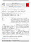
Fig. 6 (a) Sintered sample of 30 mm in diameter being exposed to plasma flame at 2700 ℃. Appearance of samples after 10 min
exposure: (b) PLS ZrB2–SiC–B4C composite, weight gain +11.67 mg/cm2 and (c) PLRS 2.0 composite, weight gain
+12.75 mg/cm2.
www.springer.com/journal/40145
J Adv Ceram 2017, 6(4): 320–329
326
12.75 mg/cm2 for PLRS 2.0 composite (Fig. 6(c)) was
recorded. Monolithic ZrB2 oxidizes to form ZrO2 and
B2O3 liquid at low temperature of the order of 450 ℃.
In the case of ZrB2–SiC composite, the silicon and
boron in the composite are oxidized at elevated
temperatures, to form a protective borosilicate glass
layer.
2ZrB2(s) + 5O2(g) → 2ZrO2(s) + 2B2O3(l) (6)
(7)
SiC(s) + 3/2O2 → SiO2(l) + CO(g)
But above 1400 ℃, the rate of volatilization of B2O3
is higher than the rate of production of B2O3. The
resultant increase in weight due to the formation of
ZrO2 is greater than the reduction in weight due to the
evaporation of B2O3. Secondary, ZrO2 precipitates on
the external surface of the oxide scale. So, the oxide
scale is a multi-phase layer with its composition,
physical properties (like viscosity), and relative amount
of phases changing with the temperature. Weight gain
measurement does not offer good support to explain any
oxidation mechanism because oxidation and
vaporization processes are advancing simultaneously.
Preliminary comparison of oxidation behavior of
different samples can be made. PLS ZrB2–SiC–B4C
composite after exposing to plasma flame of 2700 ℃
for 600 s recorded a weight gain of 11.67 mg/cm2. With
a recorded weight gain of 12.75 mg/cm2, the PLRS 2.0
composite is comparable in high temperature oxidation
resistance with PLS ZrB2–SiC–B4C composite.
The BSE image of oxide layer of PLRS 2.0
composite after 10 min exposure to plasma flame at
2700 ℃ is shown in Fig. 7(a). The corresponding XRD
pattern of PLRS 2.0 composite exposed to plasma flame
is shown in Fig. 8(a). Formation of yttria stabilized
zirconia (YSZ), silica, and YAG phases on the oxidized
surface was observed. ZrO2 alone cannot adhere to ZrB2
at high temperatures and undergo cracking. The
difference in coefficient of thermal expansion between
oxide scale and unaltered ZrB2 matrix causes weak
bonding and spalling [34]. In PLRS 2.0 composite, the
YSZ precipitates from BSZ glass and remains
embedded in complex YAG layer. Continuous and
compact ZrO2 embedded in YAG that adhere to parent
composite protect it from further oxidation by
preventing direct exposure of the ZrB2–SiC composite
to air. The EDS of parent composite of PLRS 2.0 after
10 min exposure to plasma flame at 2700 ℃ (Fig. 8(b))
revealed the retention of unaltered phases: bright phase
of ZrB2, grey phase of SiC, and dark phase of complex
YAG.
Fig. 7 BSE images of (a) oxide layer and (b) parent
composite of PLRS 2.0 after 10 min exposure to plasma
flame at 2700 ℃.
Fig. 8 (a) XRD pattern of oxide layer and (b) EDS of
parent composite of PLRS 2.0 after 10 min exposure to
plasma flame at 2700 ℃.
Since ZrB2 is electrically conductive, arc fusion
welding is possible. Due to high melting point during
fusion welding of ZrB2 based composites, oxidation and
formation of porosity in the melt fusion zone occur.
When melt pool is solidified with high volume change,
formation of voids or porosity at boundary of parent
material and fusion zone is expected. Owing to the
properties of ZrB2: high thermal expansion coefficient
(5.9×10⁻⁶ K1), high Young’s modulus (489 GPa), and
low fracture toughness (3.5 MPa·m2), rapid heating or
cooling results in large thermal gradient and thermal
shock failure through crack initiation [35]. Earlier
www.springer.com/journal/40145
J Adv Ceram 2017, 6(4): 320–329
327
efforts on fusion welding by pre heating and controlled
cooling under protective atmosphere also lead to
thermal shock failure or porosity at the weld interfaces
of TiB2–20 vol% TiC and ZrB2–20 vol% ZrC
composites [36,37].
Using a suitable filler material, formation of cracks,
pores, and voids can be avoided [38]. When arc is struck,
filler material melts and forms a liquid pool to fill the
gap between the weld surfaces to be joined. The flow of
molten filler into weld gap is similar to metal casting
into a mold. Cracks and pores that could form due to
shrinkage during the solidification of filler can be
avoided by controlling the welding speed or flow of the
molten filler into weld gap. The filler material should be
chosen with good flow ability and oxidation resistance
to flow freely into the weld gap. After studying the
oxidation behavior by exposing to plasma flame at
2700 ℃, the 2.0 composite was selected as filler for
joining PLRS composites.
Flextural test samples of size 4×5×50 mm of PLRS
2.0 composite were used for TIG welding. The weld is
very clean and free from cracks and appeared similar to
that of metal weld. Oxidation of neither parent material
nor filler material was observed. No cracks and pores on
either side of the joint interface were observed after
welding with filler (Fig. 9(a)). Examination of the cross
section of the weld revealed that the joint interface
between the parent material and filler material was very
clean and coherent (Fig. 9(b)). Typical dendrite
structure of solidified filler material can be seen.
Tungsten impurity (bright phase) picked up from
tungsten electrode was identified in Fig. 9(c). The grey
phase ZrB2 and dark phase SiC were identified through
EDS analysis. During shear testing in steel fixture the
PLRS 2.0 welds failed in weld zone. SEM image of the
morphology of fracture surface confirmed the
cleavage/brittle mode fracture (Fig. 9(d)). Shear
strength of the weld was 63.5 MPa. This is lower than
the three-point bend flextural strength of 117.6 MPa for
PLRS 2.0 composite. The shear strength of the weld
was about 55% of the flexural strength of the parent
composite.
For TPS application, high mechanical performance is
not required. High oxidation resistance and thermal
shock resistance are the main material requirements
[24]. The peak thermal stress of UHTC wing leading
edge under re-entry heating conditions is predicted to be
80 MPa [21]. It is well below the strength of PLRS 2.0
composite. The composite is shown to be oxidation
resistant, thermal shock resistant, and easily
Fig. 9 (a) and (b) BSE images of cross section of welded
PLRS 2.0 composite. (c) Filler area at higher
magnification: dark phase SiC, grey phase ZrB2, and bright
phase tungsten. (d) SEM image of fracture surface after
shear testing of the welded sample.
formable/weldable. The possibility of using the PLRS
ZrB2–SiC based composite for thermal protection of
Cf–SiC composite is examined. Rectangular pieces
(10 mm × 25 mm × 3 mm) of Cf–SiC composite are
exposed to oxy-propane flame of 2300 ℃ in 30 s
interval for 20 times with protection of PLRS 2.0
composite and without any protection. After every 30 s
of flame exposure, the samples were weighed.
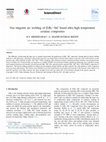
Schematic diagram of the arrangement of Cf–SiC
composite specimen for exposure to oxy-propane flame
is shown in Figs. 10(a)–10(e). Cf–SiC composite is
placed on a graphite block and covered with PLRS 2.0
composite. The sintered PLRS 2.0 composite of 30 mm
in diameter was cut to make a shape similar to leading
edge and covered the Cf–SiC composite. Without
protection the Cf–SiC composite is placed on hemi
circular pieces of PLS composite and directly exposed
to flame (Fig. 10(e)). The temperature of PLRS 2.0 and
Cf–SiC composites was measured immediately after
withdraw of the flame. The appearance of specimens
during exposure, during cooling, and after exposure for
total 600 s is shown in Fig. 10.
With protection from PLRS 2.0 composite, a weight
gain of 0.064% was recorded for Cf–SiC composite.
The bare Cf–SiC composite gained a weight of 6.66%
after a total of 600 s of exposure to oxy-propane flame.
This result clearly shows that the PLRS ZrB2–SiC based
composite is capable of providing thermal protection
for Cf–SiC composite at high temperatures. The present
results revealed the possibility of synthesis and
www.springer.com/journal/40145
J Adv Ceram 2017, 6(4): 320–329
328
Fig. 10 Arrangement of Cf–SiC composite specimen (black) for exposure to oxy-propane flame of 2300 ℃: (a) with protection
of PLRS 2.0 composite, (b) during exposure to flame, (c) during cooling, and (d) after exposure for total 600 s. (e) Cf–SiC
composite without protection, (f) during exposure to flame, (g) immediately after withdrawn of the flame, and (h) after exposure
for total 600 s.
sintering of ZrB2–SiC based composites in a single step
by PLRS at relatively low temperatures between 1550
and 1680 ℃ using ZrO2, B4C, and Si as raw materials.
The PLRS ZrB2–SiC based composites are shown to be
oxidation resistant, thermal shock resistant, easily
formable/weldable, and useful for thermal protection
application.
Ministry of Defence, Government of India, New Delhi,
India, in order to carry out the present study under project
DMR-295. They are grateful to the Director of DMRL,
Hyderabad, for his constant encouragement. The authors
acknowledge the support from various characterization
groups of DMRL.
4 Conclusions
[1]
Synthesis and sintering of ZrB2–SiC based composites
have been carried out in a single step by pressureless
reaction sintering (PLRS) using ZrO2+B4C+Si for
synthesis and Y2O3+Al2O3 for sintering. The effect of
ratios of ZrO2/B4C, ZrO2/Si, and sintering additives
(Y2O3 and Al2O3), was studied by sintering at different
temperatures between 1500 and 1680 ℃ in argon
atmosphere. ZrB2, SiC, and YAG phases were identified
in the sintered compacts. The mechanical properties of
the PLRS composite are comparable with those
properties obtained for pressureless sintered (PLS)
composites. Filler material was also prepared by PLRS
for tungsten inert gas welding of the ZrB2–SiC based
PLRS composites. The ZrB2–SiC based PLRS
composites exhibited high resistance to oxidation and
thermal shock upon exposure to plasma flame at
2700 ℃ for 600 s. The composites were found suitable
for thermal protection of Cf–SiC composites.
References
[2]
[3]
[4]
[5]
[6]
[7]
[8]
Acknowledgements
Authors acknowledge the financial support from the
Defence Research and Development Organization,
[9]
Upadhya K, Yang JM, Hoffmann WP. Materials for
ultrahigh temperature structural applications. Am Ceram
Soc Bull 1997, 76: 51–56.
Fahrenholtz WG, Hilmas GE, Talmy IG, et al. Refractory
diborides of zirconium and hafnium. J Am Ceram Soc 2007,
90: 1347–1364.
Mroz C. Zirconium diboride. Am Ceram Soc Bull 1994, 73:
141–142.
Balak Z, Shahedi Asl M, Azizieh M, et al. Effect of
different additives and open porosity on fracture toughness
of ZrB2–SiC-based composites prepared by SPS. Ceram Int
2017, 43: 2209–2220.
Balak Z, Azizieh M, Kafashan H, et al. Optimization of
effective parameters on thermal shock resistance of
ZrB2–SiC-based composites prepared by SPS: Using
Taguchi design. Mater Chem Phys 2017, 196: 333–340.
Shahedi Asl M, Golmohammadi F, Kakroudi MG, et al.
Synergetic effects of SiC and Csf in ZrB2-based ceramic
composites. Part I: Densification behavior. Ceram Int 2016,
42: 4498–4506.
Shahedi Asl M, Kakroudi MG, Farahbakhsh I, et al.
Synergetic effects of SiC and Csf in ZrB2-based ceramic
composites. Part II: Grain growth. Ceram Int 2016, 42:
18612–18619.
Farahbakhsh I, Ahmadi Z, Shahedi Asl M. Densification,
microstructure and mechanical properties of hot pressed
ZrB2–SiC ceramic doped with nano-sized carbon black.
Ceram Int 2017, 43: 8411–8417.
Ahmadi Z, Nayebi B, Shahedi Asl M, et al. Fractographical
characterization of hot pressed and pressureless sintered
www.springer.com/journal/40145
J Adv Ceram 2017, 6(4): 320–329
[10]
[11]
[12]
[13]
[14]
[15]
[16]
[17]
[18]
[19]
[20]
[21]
[22]
[23]
[24]
[25]
329
AlN-doped ZrB2–SiC composites. Mater Charact 2015,
110: 77–85.
Zhao H, He Y, Jin Z. Preparation of zirconium boride
powder. J Am Ceram Soc 1995, 78: 2534–2536.
Guo W-M, Zhang G-J. Reaction processes and
characterization of ZrB2 powder prepared by
boro/carbothermal reduction of ZrO2 in vacuum. J Am
Ceram Soc 2009, 92: 264–267.
Peshev P, Bliznakov G. On the borothermic preparation of
titanium, zirconium and hafnium borides. J Less Common
Met 1968, 14: 23–32.
Chen L, Gu Y, Yang Z, et al. Preparation and some
properties of nanocrystalline ZrB2 powders. Scripta Mater
2004, 50: 959–961.
Radev DD, Marinov M. Properties of titanium and
zirconium diborides obtained by self-propagated
high-temperature synthesis. J Alloys Compd 1996, 244:
48–51.
Zou J, Zhang G-J, Zhang H, et al. Improving high
temperature properties of hot pressed ZrB2–20 vol% SiC
ceramic using high purity powders. Ceram Int 2013, 39:
871–876.
Qiu H-Y, Guo W-M, Zou J, et al. ZrB2 powders prepared by
boro/carbothermal reduction ZrO2: The effects of carbon
source and reaction atmosphere. Powder Technol 2012, 217:
462–466.
Yuan H, Li J, Shen Q, et al. Preparation and thermal
conductivity characterization of ZrB2 porous ceramics
fabricated by spark plasma sintering. Int J Refract Met H
2013, 36: 225–231.
Yuan H, Li J, Shen Q, et al. In situ synthesis and sintering
of ZrB2 porous ceramics fabricated by spark plasma
sintering-reactive synthesis (SPS-RS) method. Int J Refract
Met H 2012, 34: 3–7.
Krishnaro RV, Alam MZ, Das DK, et al. Synthesis of
ZrB2–SiC composite powder in air furnace. Ceram Int 2014,
40: 15647–15653.
Krishnarao RV, Sankarasubrahmanian R. Thermite assisted
synthesis of ZrB2 and ZrB2–SiC through B4C reduction of
ZrO2 and ZrSiO4 in air. J Adv Ceram 2017, 6: 139–148.
Johnson SM. Ultra high temperature ceramics UHTCs.
NASA Technical Report. 2015. Available at
https://ntrs.nasa.gov/archive/nasa/casi.ntrs.nasa.gov/20150
022996.pdf.
Orcutt M. Heat resistant ceramic parts are now 3-D
printable. Available at http://www.technologyreview.com/
news/545086/heat-resistant-ceramic-parts-are-now-3-D-pr
intable/.
Eckel ZC, Zhou C, Martin JH, et al. Additive
manufacturing of polymer-derived ceramics. Science 2016,
351: 58–62.
Padovano E. Ceramic multilayer based on ZrB2/SiC system
for aerospace applications. Ph.D. Thesis. Politecnico di
Torino, 2015.
Krishnaro RV, Alam MZ, Das DK, et al. Pressureless
[26]
[27]
[28]
[29]
[30]
[31]
[32]
[33]
[34]
[35]
[36]
[37]
[38]
sintering of (ZrB2–SiC–B4C) composites with (Y2O3 +
Al2O3) additions. Int J Refract Met H 2015, 52: 55–65.
Anselmi-Tamburini U, Ohyanagi M, Munir ZA. Modelling
studies of the effect of twins on the X-ray diffraction
patterns of boron carbide. Chem Mater 2004, 16:
4347–4351.
Merzhanov AG. Self-propagating high temperature
synthesis: Twenty years of research and findings. In:
Combustion and Plasma Synthesis of High Temperature
Materials. Munir Z, Holt IB, Eds. New York: VCH, 1990:
1–53.
Barton L, Nicholls D. The hydrogenation of boron
monoxide to diborane and the reactions of boron and boron
carbide with titanium and zirconium dioxides. J Inorg Nucl
Chem 1996, 28: 1367–1372.
Ran S, van der Biest O, Vleugel J. ZrB2 powders synthesis
by borothermal reduction. J Am Ceram Soc 2010, 93:
1586–1590.
Guo WM, Tan DW, Zhang ZL, et al. Synthesis of fine ZrB2
powders by new borothermal reduction of coarse ZrO2
powders. Ceram Int 2016, 42: 15087–15090.
Zhang X, Li X, Hana J, et al. Effects of Y2O3 on
microstructure and mechanical properties of ZrB2–SiC
ceramics. J Alloys Compd 2008, 465: 506–511.
Song J-G, Li J-G, Song J-R, et al. Preparation of
high-density YAG/ZrB2 multi-phase ceramics by spark
plasma sintering. J Ceram Process Res 2007, 8: 356–358.
Fahrenholtz WG, Neuman EW, Brown-Shaklee H-J, et al.
Superhard boride-carbide particulate composites. J Am
Ceram Soc 2010, 93: 3580–3583.
Zhang X, Hu P, Han J, et al. Ablation behavior of ZrB2–SiC
ultra high temperature ceramics under simulated
atmospheric re-entry conditions. Comp Sci Tech 2008, 68:
1718–1726.
Zimmermann JW, Hilmas GE, Fahrenholtz WG. Thermal
shock resistance of ZrB2 and ZrB2–30% SiC. Mater Chem
Phys 2008, 112: 140–145.
King DS, Hilmas GE, Fahrenholtz WG. Plasma arc welding
of TiB2–20 vol% TiC. J Am Ceram Soc 2014, 97: 56–59.
King DS, Hilmas GE, Fahrenholtz WG. Plasma arc welding
of ZrB2–20 vol% ZrC ceramics. J Eur Ceram Soc 2014, 34:
3549–3557.
Krishnaro RV, Reddy GM. Gas tungsten arc welding of
(ZrB2–SiC) based ultra high temperature ceramic
composites. Defence Tech 2015, 11: 188–196.
Open Access The articles published in this journal are
distributed under the terms of the Creative Commons Attribution
4.0
International
License
(http://creativecommons.
org/licenses/by/4.0/), which permits unrestricted use, distribution,
and reproduction in any medium, provided you give appropriate
credit to the original author(s) and the source, provide a link to
the Creative Commons license, and indicate if changes were
made.
www.springer.com/journal/40145
Keep reading this paper — and 50 million others — with a free Academia account
Used by leading Academics

Estela Blaisten-Barojas
George Mason University

Wolfgang Tremel
Johannes Gutenberg-Universität Mainz

Susan Trolier-McKinstry
Penn State University
Irina Kolesnik
Moscow State University