Prace Naukowe Katedry Budowy Maszyn
1997
Ashraf I. HASSAN, Jan KOSMOL
Katedra Budowy Maszyn, Politechnika Śląska, Gliwice
AN OVERVIEW OF ABRASIVE WATERJET MACHINING
(AWJM)
Abstract: Abrasive waterjet machining (AWJM) is a new machining process, the
advantages of which include low cutting temperatures, no heat damage to the material
being cut, minimal dust, and low cutting forces. This paper presents a state of the art
review of research in this new process. The main topics discussed are mechanics of
material removal, productivity, cutting forces, surface quality and nozzle wear.
1. INTRODUCTION
Current design requirements have necessitated the need for a class of engineering materials
that possess high stiffness and reduced weight, especially at elevated service temperatures. Due
to the rapid developments in the aerospace and the automotive industries, traditional machining
of ceramics and composite materials are becoming inadequate and inefficient because of the
excessive tool wear, and the brittle nature of these materials.
Abrasive waterjet machining offers the potential for the development of a tool which is less
sensitive to material properties, has virtually no thermal effects, and imposes minimal stresses
[1]. This process was first introduced as a commercial system in 1983 for cutting of glass.
Nowadays, this process is being widely used for machining of hard to machine materials like
ceramics, ceramic composites, fiber-reinforced composites, and titanium alloys where
conventional machining is often not technically or economically feasible [2]. The fact that it is a
cold process has important implications where heat-affected zones are to be avoided [3].
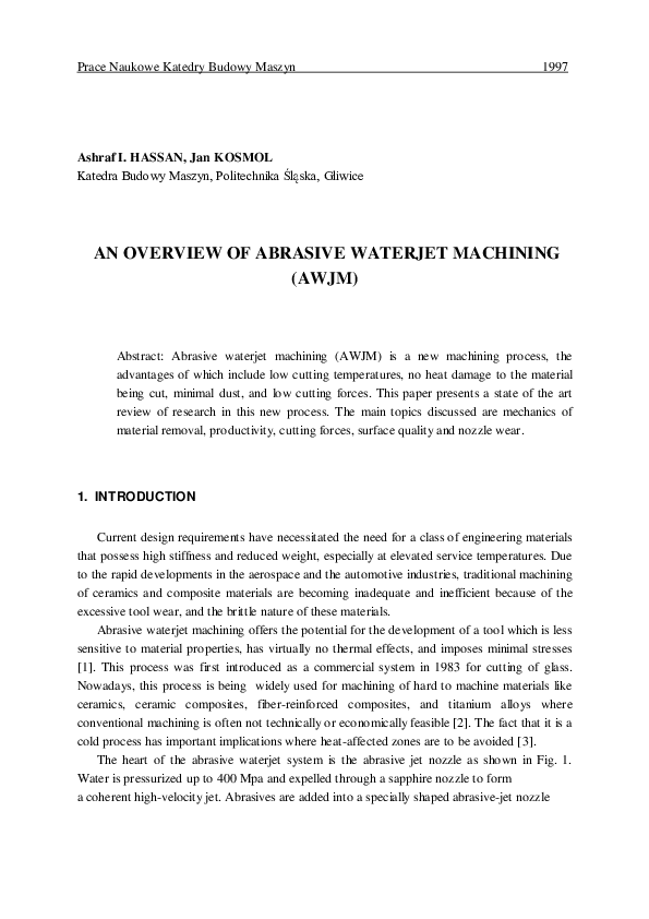
The heart of the abrasive waterjet system is the abrasive jet nozzle as shown in Fig. 1.
Water is pressurized up to 400 Mpa and expelled through a sapphire nozzle to form
a coherent high-velocity jet. Abrasives are added into a specially shaped abrasive-jet nozzle
�182
Ashraf I. HASSAN, Jan KOSMOL
from separate feed ports. Part of the waterjet's momentum is transferred to the abrasives,
Fig.1 Schematic of abrasive waterjet nozzle [4]
whose velocities rapidly increase, as a result, a focused, high-velocity stream of abrasives exits
the nozzle and performs the cutting action of the workpiece surface. The abrasive waterjet
machining system is composed of the following components [1]: high pressure intensifier,
waterjet, abrasive feed system, abrasive-jet nozzle, abrasive and water catcher, and supporting
accessories such as hoses and control valves.
There are several parameters that affect the cutting performance of the abrasive waterjet
[1]: hydraulic parameters; waterjet nozzle diameter and supply pressure, abrasive parameters;
abrasive material, abrasive size and abrasive flow rate, mixing parameters; mixing tube
dimensions and nozzle material, cutting parameters; traverse rate, stand off distance,
impingement angle and depth of cut and material to be cut.
Advantages of the process include the following [1,4] : minimal dust specially when cutting
of asbestos, less thermal or deformation stresses i.e. the workpiece is cold cut, decreased
power consumption, striation is reduced, high accuracy due to little workpiece deformation, no
fire hazards because water is inflammable, the ability to cut almost any material, deep kerfing
capability, high edge surface quality, and no heavy clamping of workpiece is needed.
�An overview of abrasive waterjet machining (AWJM)
183
The following limitations are relevant to abrasive waterjet machining [1,5]: high capital
investments are required, high cutting power is required, delamination occasionally occurs, the
jet has only a limited stability perpendicular to its own axis, and the process is noisy and
produces a great deal of spray.
The process has been extensively used in diverse fields of applications. An early study on
practical applications of AWJM [1] provided a comprehensive list of potential candidate
materials that were successfully machined. Examples of industrial applications of AWJM are
found in [6-10]. Machine tools for AWJM have been extensively developed in several
companies for the last two decades. Several machine tools' designs are found in [11-19].
This paper is a review of recent developments in AWJM research. An attempt will be made
to assess the present situation; namely, to find out what new knowledge is available today,
what is lacking in research and applications, and how the situation could be improved. The
paper will concentrate on new research findings obtained during the last two decades, which
had produced many useful theoretical as well as experimental findings. Much of the research
has dealt with mechanisms of material removal in different work materials, productivity and
surface quality and some reviews on AWJM have been conducted so far [20-25]. Comparison
studies, especially between AWJM and laser, have also been conducted [5,26].
2. MECHANICS OF MATERIAL REMOVAL
The basic mechanisms of material removal were studied extensively and established
through experimental as well as analytical work. The development of different wear
mechanisms have pushed performance level of AWJM even further. An early erosion model by
waterjets was developed by Hashish and Du Plessis [27] based on a control volume analysis to
determine the hydrodynamic forces acting on the solid boundaries of the cutting slot. The
coupled fluid-solid mechanics equations are simplified to yield a closed-form solution which
satisfies all the limiting conditions of practical cutting applications. Different materials were
characterized by friction, damping coeffecient and compressive yield strength. The equation
derived for jet penetration was later combined by the same authors [28] with empirical
equation for jet spreading and velocity decay in air to predict the depth of cut and material
removal for non-metallic materials such as wood, limestone and coal. A similar hydrodynamic
model for pure waterjet was derived by Majka [29]. Another model was developed by Wilkins
and Graham [30] for soft materials such as leather, wood, rubber and plastics based on the
deflection of the jet within the material.
The process of erosion by solid particle impact has been investigated by several notable
reseachers since 1960. The early work of Finnie [31] is still regarded as the leading work, since
then a number of researchers in AWJM have developed several cutting models on erosion.
Mechanisms of erosion of ductile materials dominated the literature until 1970. It is well
known that there is a dramatic difference in the response of ductile and brittle materials to
erosion. Finnie's model for the prediction of material removal during erosion of ductile
�184
Ashraf I. HASSAN, Jan KOSMOL
materials was derived by solving the equation of motion of a single particle striking the surface
at a shallow angle of impact in the same manner as a milling cutter or a grinding wheel. One of
the drawbacks of the model was that particle rotation during cutting was neglected. Ductile
behavior of some brittle materials was observed during erosive cutting when the abrasive size is
very small [32]. Later, an intensive work in the field of erosion was conducted by Hashish
[4,33-35]. A simplified model, based on Finnie's model, for cutting of ductile materials was
suggested which divided the cutting zone into two regions : cutting wear and deformation wear
[33].This division is based on a visualization study of the AWJM process [34] using movie
cameras at speeds of 64 and 1000 frames/s. This model uses cutting wear by single-particle
abrasive impact. Figure 2 shows a schematic of the different cutting stages. A steady-state
interface to a depth (hc) exists at the top of the kerf. Below (hc), a step of material exists and
appears to move under the impact of the jet until it reaches the final depth (h). The kerf
curvature at depth (hc) changes suddenly, marking a transition from one material removal mode
to another [36,37]. The abrasive waterjet material removal process is a complex erosion
process where more than one mode contributes to the erosion results. Material removal takes
place as a result of the erosive action of large number of impacts (10 3 /s) by the abrasive
particles [38].
Fig. 2 Cutting zones of abrasive waterjet kerfs [36]
Two mechanisms have been identified as the dominant modes of material removal. These
are the cutting wear mode and the deformation wear mode. The surface produced by the first
mode is a relatively smooth due to a cutting wear at a shalow angle of impact and it exists at
�An overview of abrasive waterjet machining (AWJM)
185
the upper portion of the cutting kerf [35]. The material hardness is the most relevant material
property to this mode [36]. The surface produced by the other mode is striated due to a
deformation wear mode at large angles of impact which is characterized by material removal
due to excessive plastic deformation [35].This wear mode results in an unsteady penetration
process. The modulus of elasticity was found to correlate well with this mode of material
removal [36,37]. Recent studies in AWJM of graphite/epoxy composites pointed out the
existence of a small initial damage zone near the jet entrance in addition to the previous two
zones [39,40]. A recent study found that the depth of the cutting wear zone could be increased
by 30 % by applying a small oscillation to the AWJ head [41]. Momber [42] reviewed the
different formulas for the depth of cut obtained by different researchers.
The relative contribution of each mode to the total depth of cut depends on the traverse
rate [4]. The depth over the cutting wear mode (hc) is obtained by the following expression
[35], see Fig.3:
hc
where,
(V0 / CK ) d j
)]2 /5 (Ve / CK )
[( p u d j 2 / 14 m
(1)
u
Vo
CK
dj
p
traverse rate
initial abrasive particle velocity
characteristic velocity
jet diameter
density of abrasive particle
abrasive particle mass flow rate
m
Ve
threshold particle velocity
whereas the depth of cut by deformation wear mode (hd) is calculated by the following
equation [35] :
hd
1
(Ve Vo ) 2 [C f Vo / d j (Vo Ve )]
[ d j u / 2 C1 m
(2)
workpiece flow stress
C1
ratio of effective particle velocity
Cf
coeffecient of friction on kerf wall
The developed model can be easily used for predictions. Two properties are needed for a
specific material: flow stress and a critical velocity. These can be determined based on
experimental results. The prediction accuracy of the model was found to be very adequate for
cutting applications. The total depth of cut (h) can be expressed as:
where,
h = hc + hd
(3)
�186
Ashraf I. HASSAN, Jan KOSMOL
The critical traverse rate (uc) at which cutting wear terminates is [4] :
Fig. 3 Erosion zones in AWJM [35]
uc
m V 2
20 dj 2
(4)
where,
V
particle velocity
It was noted that the erosion mechanism in silicon carbide-reinforced aluminium metal
matrix composite differs slightly. The aluminium matrix is subject to microcutting, such as
ductile materials, while the SiC particulates being removed by shovelling action of the incoming
jet [43]. A recent work by Finnie [44] reviewed the research work of erosion by solid particles
entrained in a liquid jet during the last four decades. Finnie confirmed again that the erosion
mechanism dominating ductile materials is plastic deformation. Observations of scanning
electron microscopy showed that some particles remove a chip as in metal cutting, others leave
material piled up at the sides or the end of the crater. This raised material is presumably
removed easily by subsequent particles. A recent study used a new approach for modeling the
AWJM process of ductile materials, based on experimental results, in order to obtain metal
removal rates as a function of particle velocity. It has been shown that the material is cut
because a threshold water pressure is exceeded. A correlation relating material removal rate to
the particle velocity was derived [45]. A more recent study modeled AWJM of ductile
�An overview of abrasive waterjet machining (AWJM)
187
materials on the basis of Finnie's and Hashish's models but modified by using the concept of
generalised kerf shape i.e. accounting for the variations in the kerf width. The basic material
property which determines the total depth of cut is suggested to be the melting specific energy
rather than the elastic modulus as previous studies [46].
In brittle materials, erosion occurs by the propagation and intersection of cracks produced
by impacting particles. At a threshold load a median crack will propagate downwards from the
base of the plastic zone. This crack does not remove material but it does degrade strength [31].
A model of AWJM of polycrystalline ceramics was initiated by Zeng and Kim [47,48]. Erosion
mechanisms observed include intergranular network cracking due to fractures caused by impact
induced stress waves and plastic flow. Material removal due to network cracking was
calculated with a crack network model which relates the fracture surface energy in forming the
crack network to the energy of the impact induced stress waves, while plastic flow is evaluated
with Finnie's model. It was found that an incident angle of 90 is optimum for maximum
material removal to the contrast of metals where the maximum material removal is obtained at
smaller incident angles as was previously pointed out by Finnie [31]. A semi-empirical model
for grey cast iron was developed based on wear particle analysis because eroded particle size
distribution may give information about the general erosion mechanism. The erosion
mechanism does not depend significantly on pressure, but pressure was found to influence the
efficiency of the material removal process. The erosion mechanism was suggested as
microcrack network and the widening of the cracks by a high-speed water [49,50]. More
recent studies [51,52] suggest erosion mechanisms for brittle materials on the basis of Finnie's
[31] and Zeng's [47] models for brittle materials but taking into account the size and shape of
the abrasive particles. Two zones of material removal exist, in the first the material is removed
by microcutting and fracture because of the impact of abrasive particles at shallow angle of
impact. In the second zone, material is removed by plastic deformation and fracture due to the
orthogonal impact of abrasive particles. Meanwhile, variations in the width of cut has been
neglected. It was pointed out that the use of spherical blunt abrasive particles will lead to more
fracture.
Turenne and Fiset [53] modeled the abrasive particle trajectories during erosion by a slurry
jet using an analysis based on potential and stream functions. This leads to the determination of
the velocity components of the jet. It was shown that the predominant variable affecting the
impact parameters is the particle size.
Up to date, there has been no attempt at analyzing abrasive water jet cutting using the
powerful tool of finite element method. A preliminary effort of modeling the impact of a solid
surface by a single water drop using a dynamic linear finite element model was carried out by
Alder [54] who was concerned with rain erosion of aerospace vehicles which is similar to
waterjet erosion.
3. PRODUCTIVITY
�188
Ashraf I. HASSAN, Jan KOSMOL
Significant experimental as well as analytical work on productivity has been reported. An
early experimental work on productivity was reported by Hashish [55]. The important
parameters affecting the productivity in AWJM are abrasive flow rate, pressure, stand off
distance, traverse rate, abrasive material and abrasive particle size. The effect of these
parameters on productivity will be discussed. The effect of abrasive flow rate on the depth of
cut is shown in Fig. 4. A certain critical flow rate exists beyond which the
Fig. 4 Effect of abrasive flow rate on depth of
cut [55]
Fig. 5 Effect of pressure on depth of cut [55]
optimum abrasive flow rate exists at which the depth of cut peaks. The effect of pressure on
the depth of cut is shown in Fig. 5. An optimum pressure should be determined to compromise
between the rate of cutting and power requirements. High pressures result in deeper cuts and
higher traverse rates. However, it was shown that higher pressures result also in lower
hydraulic efficiency, more frequent maintenance, high wear rates of mixing tubes, and
fragmentation of particles before they exit the nozzle. Consequently, hydraulic power is best
utilized at an optimum pressure e.g. over 240 Mpa [56]. The effect of stand off distance on the
depth of cut is shown in Fig. 6. The effect of stand off distance on material removal
is shown in Fig. 7. It can be seen that there is an optimum stand off distance for maximum
volume removal rate. An increased stand off distance is associated with a decrease in volume
removal. However, increasing the abrasive flow rate does not significantly alter the trend of the
�An overview of abrasive waterjet machining (AWJM)
189
effect of stand off distance. Increasing the traverse rate will result in reduced depth of cut, see
Fig. 8.
Fig. 6 Effect of stand off distance on depth of
cut [55]
Fig. 7 Effect of stand off distance on volume
removal [4]
Fig. 8 Effect of traverse rate on depth and
uniformity of cut [4]
Fig. 9 Effect of stand off distance and
traverse rate on shape of cut [4]
�190
Ashraf I. HASSAN, Jan KOSMOL
However, volume removal rates may increase with increasing the traverse rate. Figure 9 shows
a diagrammatic representation of the effects of both stand off distance and traverse rate in the
slot geometry. The use of hard abrasives would be suitable for fast material removal rates,
whereas the use of soft, frangible abrasives may be suitable for finishing. Finer particles
produce finer surfaces. However, reduced volume removal rates are associated with finer
particles [4].
An early attempt to apply AWJ to milling was conducted by Hashish [4]. The preliminary
results was encouraging in providing reasonable metal removal rates. But on the other hand,
controlling the depth of cut was a difficult problem and an optimum machining strategy was
needed to maximize metal removal rates and minimize the surface texture effects. Hashish [57]
investigated the optimization of factors affecting AWJM due to the large number of parameters
and factors involved. Significant improvements were found to be obtained. The relative
significance of AWJM parameters on machining results were qualitatively summarized. Hashish
[58] studied the effect of jet angle on productivity and found the same conclusion of Finnie
[31] that there is an optimum angle for maximum depth of cut. He extended his study to
milling, turning and drilling. It has been shown that metal removal rates can be increased by a
factor of three when the jet is angled. The jet angle was also found to affect surface roughness
and straightness of the machined surfaces. In a recent study on pocket milling using AWJ, Paul
et al [59] developed empirical models using regression analysis. The depth of the pocket could
be controlled to a value of 0.04 mm. A recent study on AWJ turning showed that the material
removal rate trends are similar to those in linear cutting with AWJ [60]. The volume removal
rates while machining modern ceramics were found to be primarily dependent on pressure and
abrasive flow rate [61].
4. CUTTING FORCES AND TEMPERATURES
Few researchers were concerned with cutting forces and temperature. This may be
attributed to the fact that AWJM is a cold cutting process and cutting forces are very low. The
first study on thermal energy distributions in the workpiece during cutting with AWJ was
conducted by Ohadi et al. [38]. From the results in Fig. 10, two important trends can be
identified, where (y) is the distance from the cutting interface perpendicular to jet direction, (Z)
is the depth in the workpiece parallel to jet direction, (t) is the workpiece thickness and (T o) is
the ambient temperature. First, it is seen that highest temperatures occur at the immediate
vicinity of the cutting interface whereafter they experience a sharp decay with increasing
distance from the cutting interface. However, increasing pressure increases temperature due to
higher waterjet velocity, as shown in Fig. 11, where the numbers on the x-axis represent the
positions of thermocouples. It was also observed that a material with higher thermal
conductivity experiences higher temperatures during the cut. A more recent study on
temperature distribution in the workpiece modeled the problem of temperature distribution
�An overview of abrasive waterjet machining (AWJM)
191
mathematically by feeding experimental temperature data to a heat conduction algorithm,
which determines the heat flux in the workpiece. This heat flux is fed into a heat conduction
model to calculate the corresponding temperature distribution in the workpiece [62]. One of
the limitations of the model is its inability to predict temperatures accurately at the entry and
exit zones. However, there is still a lack of understanding in this field.
distance from cutting interface
Fig. 10 Variation of averaged maximum
temperatures with respect to
distance from interface [38]
distance from cutting interface
Fig. 11 Effect of pressure on
temperature distributions in the workpiece
[38]
In an early study on cutting forces in pure waterjet cutting, Decker et al [63] suggested a
model for jet forces based on jet energy. It was found that the jet force increases with an
increase in pressure and waterjet nozzle diameter and it is affected by nozzle geometry.
Kovacevic [64] modeled cutting forces in AWJM process. The effects of abrasive waterjet
nozzle diameter, abrasive flow rate, waterjet pressure, stand off distance and traverse rate are
shown in Fig. 12. It could be concluded that the workpiece normal force will increase with
increasing waterjet pressure, abrasive flow rate and nozzle diameter. Whereas, it will decrease
with increasing stand off distance and will be only slightly affected by traverse rate. A large
increase in the magnitude of the normal force will indicate the presence of nozzle wear and
show that the depth of cut is exceeding the acceptable limit [64]. Typical static cutting force
signal and the corresponding dynamic force signal are given in Fig.13 [2]. Based on Decker's
�192
Fig. 12 Effect of AWJ cutting conditions on
workpiece normal force [64]
Ashraf I. HASSAN, Jan KOSMOL
Fig.13 Typical cutting force signals [2] (a)
static force (b) dynamic force
model, a recent study [65] showed the importance of the ratio of abrasive mass flow rate to
water mass flow rate in affecting jet forces.
5. SURFACE QUALITY
Valuable contributions have already been made in the past two decades in this field. Several
authors studied particularly the effect of AWJM on the surface quality of ductile materials such
�An overview of abrasive waterjet machining (AWJM)
193
as steels [66,67], while others concentrate on ceramics [41], composite materials [42,68-71],
titanium alloys [66] and amorphous alloys [72].
5.1 Kerf width and taper
Hamatani and Ramulu [71] studied the effect of traverse rate and stand off distance on the
kerf width and taper. The surface quality of abrasive waterjet piercing is evaluated in terms of
hole taper as a function of stand off distance, while for the abrasive waterjet slotting both kerf
width taper and surface roughness are reported as a function of machining conditions. Figure
14 shows the taper results for the slot cutting of metal matrix composites for three different
mesh sizes of garnet. There appears to be an optimum traverse rate for a given abrasive particle
size and flow rate that produces a slot that is not tapered. It is also interesting to note
Fig. 14 Kerf taper ratio versus traverse rate
[71]
Fig. 15 Hole taper ratio versus stand off
distance [71]
that at extremely slow traverse rates (less than 50 mm/min) the kerf width of the top surface
was less than the kerf width of the bottom surface. A possible reason for this is the relatively
long jet exposure times. Figure 15 shows the taper results in the case of piercing of metal
�194
Ashraf I. HASSAN, Jan KOSMOL
matrix composite (MMC), Fig. 15 (a) and ceramic matrix composite, Fig. 15 (b). A linear
relationship apparently exists between stand off distance and hole taper in the case of MMC,
while the variation in case of ceramic matrix composite is nonlinear. A model for predicting the
kerf taper in graphite/epoxy composite was recently developed by Ramulu and Arola [40].
Afterwards, it was extended for kerf profile prediction and the effect of cutting parameters on
kerf characteristics could be obtained using ANOVA techniques [39].
5.2 Surface texture
Hashish [66,68] was pioneer in exploring the effects of AWJM on the surface quality of the
produced surfaces, hence helped to obtain better surface quality than ten years ago. The
surface texture that may be associated with abrasive waterjet machining include: surface
waviness, burr formation, surface finish and lay. The finish of a surface machined by abrasive
waterjet exhibits two distinct contributions from the process: roughing occurring at the upper
portion of the kerf, due to the micro effects of each impacting particle and waviness or
striation, occurring at the lower portion of the kerf, due to jet penetration and loss of stability
as the cutting depth increases. A smooth cut can be obtained by extending the cutting wear
over the entire thickness of the material. This can be achieved by increasing the jet cutting
power or by reducing the traverse rate [73]. The surface roughness was found to depend on
the micromachining process of particle-material interaction. As the traverse rate and abrasive
particle size increase, the surface roughness increases as shown in Fig. 16(a) [71,74]. It is clear
that an increase in the abrasive flow rate produces better surface finish, Fig. 16 (b). In a study
on AWJM of metal and ceramic matrix composite materials using scanning electron
microscopy, Savrun and Taya [70] obtained relatively smooth surfaces with minimum
subsurface microstructural damage. Blickwedel et al [75] developed a semi-empirical equation
for the prediction of surface roughness as a function of both traverse rate and pressure using
regression analysis. Another mathematical model for the prediction of surface roughness of
graphite/epoxy composite was developed by Ramulu and Arola [40] using ANOVA regression
techniques and can be used for determining cutting parameters for tailored surface quality.
Chao et al [67] evaluated generated surfaces using surface topography analysis. It was found
that the smooth zone has a random, moderately isotropic texture. The extent of the smooth
zone depends on the cutting conditions e.g. traverse rate, depth of cut and cutting direction.
Surface roughness was shown to strongly depend on depth of cut and traverse rate in the
�An overview of abrasive waterjet machining (AWJM)
195
striation zone. An oscillation applied to the abrasive waterjet nozzle head was found to
Fig. 16 Surface roughness versus traverse
rate [71]
Fig. 17 Effect of traverse rate on surface
waviness [66]
produce superior surface texture results for cutting of ceramics. The smooth zone depth
increased by more than 30% as compared to that without oscillation. Also the striations were
observed to decrease [41].
The surface waviness was found to depend primarily on the dynamic parameters, i.e.
pressure, abrasive flow rate, and traverse rate. Figure 17 shows the effect of traverse rate and
abrasive flow rate on surface waviness. As can be seen, the surface waviness is critically
dependent on the traverse rate.
Burrs may form at the exit side of thin sheet metal cut with an abrasive waterjet. Figure 18
shows data on the height of burrs formed at different traverse rates and abrasive flow rates.
The mechanism causing burr formation is similar to that in mechanical sawing, i.e. the material
at the bottom of cut is bent rather than removed.
�196
Ashraf I. HASSAN, Jan KOSMOL
Fig. 18 Burr height produced by abrasive waterjet cutting [66]
5.3 Surface integrity
The surface integrity effects are defined as particle deposition, delamination, gouging,
cracking, work hardening and heat affected zones. Particle deposition increases with increasing
angle of attack and decreasing particle velocities. A recommended practice in using abrasive
waterjet is that the abrasive supply be turned off after a surface has been generated by linear
cutting, turning and milling, so that the waterjet alone can be used to clean the surface of
particles that may have been imbedded.
Delamination may be observed when machining layered materials such as graphite epoxy
composites and kevlar. Delamination occurs only if the deformation wear mode of erosion
exists [66]. On the other hand, delamination is a major concern in AWJM of composite
materials. The mechanism of delamination was studied using fracture mechanics and the
optimum waterjet pressure for no delamination is now predictable [76].
Goughing are dimples about 10 microns in diameter observed microscopically. These
dimples are particles pulled from the surface. The surfaces produced with abrasive waterjet are
free from microstructural distortion.
For brittle materials such as glass, cracks may be evident on the kerf edge. It was observed
that microcracks less than one micron deep may form when abrasive particles less than 10
microns in size are used.
�An overview of abrasive waterjet machining (AWJM)
197
Changes in hardness due to abrasive waterjet machining are insignificant. Also abrasive
waterjet process does not affect the mechanical characteristics of the material.
Strains occurring in erosion must be very large, and in addition, the surface will become
work-hardened by the eroding particle [44]. Erosion also involves very high strain rates. This
tends to increase the flow stress [31]. In a recent research work, Tönshoff et al [77] observed
that the high-frequency impact of pure waterjet on the surface of steel, using pressures up to
100 Mpa, causes local plastic deformation. As a result, high compressive residual stresses are
induced in the surface-near layers. Fatigue strength was also shown to increase. The effect on
the depth only reaches the surface-near material within distances from the surface of up to
approximately 30 microns.
The inspection of abrasive waterjet machined surfaces indicated that no heat affected zones
are associated with the cutting process. Even if high temperatures occur for very short periods
of time upon the impact, these are removed as the kerf is generated.
6. NOZZLE WEAR
The mixing tube, where the abrasives are mixed, accelerated and focused with the highpressure waterjet, is the component of the abrasive waterjet that receives the greatest wear.
Hashish [78,79] tested a wide range of candidate nozzle materials. The tungsten carbide grades
exhibited more longevity than the hard ceramics such as boron carbide, when garnet abrasives
were used. The reverse trend was observed with aluminum oxide abrasives. Wear mechanisms
along the mixing tube change from erosion at the upstream to abrasion at the downstream
sections. The development of nozzle wear as a function of operating time shows a 50 %
increase in the nozzle diameter after only 80 minutes of operation as observed by König and
Schmelzer [80]. A slight increase in the nozzle wear is also observed when the pressure
increases from 200 Mpa to 300 Mpa. On the other hand, surface roughness and kerf taper
progressively increase as the nozzle wear increases. The effect of mixing tube length on nozzle
wear is shown in Fig. 19. The longer the mixing tube, the slower the wear rate. The reason is
that the velocity vectors of the particles become parallel to the wall when the tube length
increases and only the abrasion mode exists. Figure 20 shows the effect of mixing tube material
on wear. The boron carbide tube exhibited a faster wear rate than the tungsten carbide tube.
The reverse trend is observed when using aluminium oxide abrasives. A recent research work
on the wear of mixing tube materials has shown the superiority of a new nozzle material,
composite carbide over tungsten carbide and boron carbide, due to its particular combination
of hardness and toughness [81]. Schwetz et al [82] suggest the use of boron carbide nozzles
with hard abrasives such as aluminum oxide for machining of very hard and tough workpieces
such as ceramics and cermets.
�198
Ashraf I. HASSAN, Jan KOSMOL
Fig. 19 Reduced wear rates with increased Fig. 20 Wear of different nozzle materials
nozzle length [78]
using garnet abrasives [78]
7. CONTROL AND MONITORING
Researchers have been becoming more interested and active in this field. Kovavevic [83]
develpoed a wear sensor system for on line tracking of abrasive water jet nozzle wear based on
conductive loops placed on ceramic substrate and embedded in the tip of the nozzle. Hence,
compensation for the increase in AWJ nozzle diameter could be made. Afterwards, he [64]
showed that the workpiece normal force generated by the abrasive water jet could be used as
an indicator of the jet penetration, and that a force-feed back control holds a promise as an
effective way to regulate the depth of jet penetration. A correlation between depth of cut and
process variables, based on experimentation, was derived using multiple regression analysis.
Another monitoring system for the AWJ nozzle wear based on acoustic signals generated by
the AWJ was derived by Kovacevic et al. [84]. This model has the possibility of monitoring and
compensating nozzle wear using the frequency domain acoustic signals generated by the jet
exiting the nozzle. An artificial neural network is capable of determining the nozzle diameter
corresponding to any unknown sound signal [85]. Kovacevic and Fang [86] showed that fuzzy
rules could be applied in AWJM to determine WJ cutting parameters for milling instead of the
tedious and time consuming experimentation. A more recent study [87] derived a mathematical
model for the estimation of the energy absorption capability of materials during AWJM based
on the energy balance inside the workpiece. It is shown that the energy absorption depends on
the depth of cut.
�An overview of abrasive waterjet machining (AWJM)
199
CONCLUSIONS
AWJM is a comparatively recent machining process. It is mainly used for machining of high
strength and difficult-to-cut materials due to its low cutting temperature, no heat damage to the
surface, and low cutting forces. In recent years the process has been applied to different
materials such as ceramics, composites, titanium alloys and even amorphous alloys. As a result
of the present review, the following conclusions could be drawn :
1.
The abrasive waterjet material removal process is a complex erosion process where more
than one mode contributes to the erosion results. Two mechanisms have been identified
for ductile materials as the dominant modes for material removal, cutting wear mode and
deformation wear mode.
2.
High surface quality was obtained with abrasive waterjet cutting by using high pressures
and low traverse rates. The process does not generally affect the integrity of the surface.
3.
The depth of cut varies linearly with the abrasive flow rate and pressure. Low traverse
rates are more efficient for deep cuts. The smaller the stand off distance, the deeper the
cut.
4.
It was shown that the maximum temperature occurs in the immediate vicinity of the
cutting interface and decays rapidly thereafter with increasing distance from the cutting
interface.
5.
The hardness and toughness of the abrasive waterjet nozzle material should both exceed
certain threshold values for effective performance.
REFERENCES
[1]
[2]
[3]
[4]
[5]
[6]
[7]
Hashish M. : Cutting with Abrasive Waterjets, Mechanical Engineering, Vol. 106, pp.
60, March 1984.
Kovacevic R., Mohan R., Zhang Y. M. : Cutting Force Dynamics as a Tool for Surface
Profile Monitoring in AWJ, Transactions of the ASME, Journal of Engineering for
Industry, Vol. 117, pp. 340, Aug 1995.
Tap the potential for plate profiles, Machinery and Production Engineering, Vol. 147,
No. 3755, pp. 32, 3 Mar 1989.
Hashish M. : An Investigation of Milling with Abrasive-Waterjets, Transactions of the
ASME, Journal of Engineering for Industry, Vol. 111, pp. 158, May 1989.
Cutting Options for the Modern Fabricator, Welding and Metal Fabrication, Vol. 64, No.
5, pp.186, 1996.
Kulpa, C. : Hochdruck-Wasserstrahlschneiden von Kuntostoffen : Souveräne
Technologie, Schweitz Maschinenmarkt, No. 6, pp.12, 1995.
Harris I. D. : Abrasive Waterjet Cutting and Its Applications at TWI (UK), Welding in
the World, Vol. 33, No. 4, pp. 277, 1994.
�200
[8]
[9]
[10]
[11]
[12]
[13]
[14]
[15]
[16]
[17]
[18]
[19]
[20]
[21]
[22]
[23]
[24]
[25]
Ashraf I. HASSAN, Jan KOSMOL
Fecht N. : Wasser marsch, Industrie Anzeiger, No. 12, pp. 52, 1994.
Struck D. : Titan und Aluminium-bleche im Flugzeugbau mit AbrasiveHochdruckwasserstrahlschneiden, Werkstatt und Betrieb, Vol. 123, No. 11, pp. 861,
1990.
Engemann B. K. : Water Jet Cutting of Fibre Reinforced Composite Materials, Industrial
& Production Engineering, No. 3, pp. 162, 1981.
Vebersax H. P., Christen G., Barmettler K. : Achtachsige Wasserstrahl- schneidanlage,
Technische Rundschau, Vol. 88, No. 1/2, pp. 12, 1997.
Abrasivestrahlschneiden in der dritten Dimension, Lasermarket, pp. 64, 1997.
Für dickere Dicken - Wasserstrahlschneiden- eine Alternative zum Laserstrahlschneiden
im Lohnauftrag, Machine + Werkzeug, No. 10, pp. 46, 1996.
UK's first 5-axis Subcon Waterjet Ordered, Sheet Metal Industries, Vol. 72, No. 9, pp.
13, 1995.
Mehrköpfige Wasserstrahlschneidanlage erhöht Produktivität, Maschinenmarket, Vol.
101, No. 25, pp. 34, 1995.
Schneiden mit dem Wasser-Abrasivstrahl : Scharfer Strahl trennt Material, Schweitz
Maschinenmarkt, No. 17, pp. 40, 1994.
Olsen C. M., Todd R. H. : Designing and Building a Water Jetcutting Machine,
Mechanical Engineering, Vol. 114, No. 7, pp. 68, 1992.
Abrasive Water Jet Cutting, Glass International, No. 6, pp. 41, 1989.
Hashish M. : Comparative Evaluation of Abrasive Liquid Jet machining Systems,
Transactions of the ASME, Journal of Engineering for Industry, Vol. 115, No. 1, pp. 45,
Feb 1993.
Oczoœ K. : Obróbka Wysokociœnieniowym Strumieniem Wody, Mechanik, No. 2/3, pp.
85, 1989.
Oczoœ K., £abudzki R. : Óbróbka Strumieniem Wodo- Œciernym Materia³ów
Metalowych i niemetalowych (Czêœæ I), Mechanik, Rok LXV, Vol. 65, No. 11, pp.
349, 1992.
Oczoœ K., £abudzki R.: Obróbka Strumieniem Wodo-Œciernym Materia³ów
Metalowych i niemetalowych (Czêœæ II), Mechanik, Rok LXV, Vol. 65, No. 12, pp.
389, 1992.
Borkowski J., Perec A., Siek W. : Nowe Osi¹gniêcia W³asne w Intensyfikacji Obróbki
Wysokoprêdkoœciow¹ Strug¹ Hydroœciern¹ o Obnizonym Ciœnieniu, Naukowa Szko³a
Obróbki Œciernej, Koszalin, Vol. XVI, pp. 283, 1993.
Borkowski J., Chudy J., Reczko M. : Technologiczne i Konstrukcyjne Aspekty
Intensyfikacji Wysokociœnienowej Obróbki Hydroœciernej, Naukowa Szko³a Obróbki
Œciernej, Koszalin, Vol. XVI, pp. 289, 1993.
Hoogstrate, A. M., et al : Opportunities in Abrasive Water-Jet Machining, Annals of the
CIRP, Vol. 46, No. 2, pp. 697, 1997.
�An overview of abrasive waterjet machining (AWJM)
201
[26] Zheng H. Y., Han Z. Z., Chen Z. D., Chen W. L., Yeo S. : Quality and Cost
Comparisons Between Laser and Waterjet Cutting, Journal of Materials Processing
Technology, Vol. 62, No. 4, pp. 294, 1996.
[27] Hashish M., Du Plessis M. P. : Theoretical and Experimental Investigation of Continuous
Jet Penetration of Solids, Transactions of the ASME, Journal of Engineering for
Industry, Vol. 100, No. 1, pp. 88, 1978.
[28] Hashish M., Du Plessis M. P. : Prediction Equations Relating High Velocity Jetcutting to
Stand off Distance and Multipasses, Transactions of the ASME, Journal of Engineering
for Industry, Vol. 101, pp. 311, Aug 1979.
[29] Majka K. : Model W³aœciwoœci Hydrodynamicznych Wysokociœnieniowej Strugi
Cieczy, Mechanik, No. 7, pp. 248, 1991.
[30] Wilkins R. J., Graham E. E. : An Erosion Model for Waterjet Cutting, Transactions of
the ASME, Journal of Engineering for Industry, Vol. 115, No. 1, pp. 57, Feb 1993.
[31] Finnie I. : Erosion of Surfaces by Solid Particles, Wear, Vol. 3, No. 3, pp. 87, 1960.
[32] Sheldon G. L., Finnie I. : On the Ductile Behavior of Nominally Brittle Materials During
Erosive Cutting , Transactions of the ASME, Journal of Engineering for Industry, Vol.
88, No. 4, pp. 387, 1966.
[33] Hashish M. : A Modeling Study of Metal Cutting with Abrasive Waterjets, Transactions
of the ASME, Journal of Engineering Materials and Technology, Vol. 106, No. 1, pp.
88, 1984.
[34] Hashish M. : Visualization of the Abrasive-Waterjet Cutting Process, Experimental
Mechanics, pp. 159, June 1988.
[35] Hashish M. : A Model for Abrasive-Waterjet (AWJ) Machining, Transactions of the
ASME, Journal of Engineering Materials and Technology, Vol. 111, pp. 154, Apr 1989.
[36] Hashish M. : Wear Modes in Abrasive-Waterjet machining, Transactions of the ASME,
PED- Vol. 54/TRIB- Vol. 2, Tribological Aspects in Manufacturing, pp. 141, ASME
1991.
[37] Hashish M. : Material Properties in Abrasive-Waterjet machining, Transactions of the
ASME, Journal of Engineering for Industry, Vol. 117, pp. 578, Nov 1995.
[38] Ohadi M.M., Ansari A. I., Hashish M. : Thermal Energy Distributions in the Workpiece
During Cutting with an Abrasive Waterjet, Transactions of the ASME, Journal of
Engineering for Industry, Vol. 114, pp. 67, Feb 1992.
[39] Arola D., Ramulu M. : A study of Kerf Characteristics in Abrasive Waterjet Machining
of Graphite/Epoxy Composite, Transactions of the ASME, Journal of Engineering
Materials and Technology, Vol. 118, pp. 256, Apr 1996.
[40] Ramulu M., Arola D. : The influence of Abrasive Waterjet Cutting Conditions on the
Surface Quality of Graphite/Epoxy Laminates, International Journal of Machine Tools
and Manufacture, Vol. 34, No. 3, pp. 295, 1994.
�202
[41]
[42]
[43]
[44]
[45]
[46]
[47]
[48]
[49]
[50]
[51]
[52]
[53]
[54]
[55]
Ashraf I. HASSAN, Jan KOSMOL
Siores E., Wong W. C. K., Chen L., Wager J. G. : Enhancing Abrasive Waterjet Cutting
of Ceramics by Head Oscillation Technique, Annals of the CIRP, Vol. 45, No. 1, pp.
327, 1996.
Momber A. : Neue Erkenntnisse auf dem Gebiet des Abrasiv-strahlschneidens, wt, Vol.
83, No. 11/12, pp. 74, 1993.
Ramulu M., Raju S. P., Inove H., Zeng J. : Hydro-Abrasive Erosion Characteristics of 30
vol % SiC/6061-T6 Al Composite at Shallow Impact Angles, Wear, Vol. 166, No. 1, pp.
55, 1993.
Finnie I. : Some Reflections on the Past and Future of Erosion, Wear, Vol. 186-187, pp.
1, 1995.
Tazibt A., Abriak N., Parsy F. : Interaction of Abrasive Waterjet with Cut Material at
High Velocity of Impact-development of an Experimental Correlation, European Journal
of Mechanics and Solids, Vol. 15, No. 6, pp. 1037, 1996.
Paul S., Hoogstrate A. M., Van Luttervelt C. A., Kals H. J. J. : Analytical and
Experimental Modeling of the Abrasive Waterjet Cutting of Ductile Materials, Journal of
Materials Processing Technology, Vol. 73, pp. 189, 1998.
Zeng J., Kim T. J. : An Erosion Model of Polycrystalline Ceramics in Abrasive Waterjet
Cutting, Wear, Vol. 193, No. 2, pp. 207, 1996.
Zeng J., Kim T. J. : An Erosion Model for Abrasive Waterjet Milling of Polycrystalline
Ceramics, Wear, Vol. 199, No. 2 , pp. 275, 1996.
Momber A. W., Kwak H., Kovacevic R. : Investigation in Abrasive Waterjet Erosion
Based on Wear Particle Analysis, Transactions of the ASME, Journal of Tribology, Vol.
118, No. 4, pp. 759, 1996.
Momber A. W., Kwak H., Kovacevic R. : Alternative Method for the Evaluation of the
Abrasive Waterjet Cutting of Grey Cast Iron, Journal of Materials Processing
Technology, Vol. 52, pp. 65, 1997.
Paul S., Hoogstrate A. M., Van Luttervelt C. A., Kals H. J. J. : Energy Partitionning in
Elasto-Plastic Impact by Sharp Abrasive Particles in the Abrasive Waterjet Machining of
Brittle Materials, Journal of Materials Processing Technology, Vol. 73, pp. 200, 1998.
Paul S., Hoogstrate A. M., Van Luttervelt C. A., Kals H. J. J. : Analytical Modeling of
the Total Depth of Cut in the Abrasive Waterjet Machining of Polycrystalline Brittle
Materials, Journal of Materials Processing Technology, Vol. 73, pp. 206, 1998.
Turenne S., Fiset M. : Modeling of Abrasive Particle Trajectories During Erosion by a
Slurry Jet, Wear, Vol. 162-164, pp. 679, 1993.
Alder W. F. : Waterdrop Impact Modeling, Wear, Vol. 186-187, pp. 341, 1995.
Hashish M. : Steel Cutting with Abrasive Waterjets, Proceedings of the 6th International
Symposium on Jet Cutting Technology, BHRA Fluid Engineering, Cranfield, England,
pp. 465, 1982.
�An overview of abrasive waterjet machining (AWJM)
203
[56] Hashish M. : Pressure Effects in Abrasive Waterjet (AWJ) Machining, Transactions of
the ASME, Journal of Engineering Materials and Technology, Vol. 111, pp. 221, Jul
1989.
[57] Hashish M. : Optimization Factors in Abrasive Waterjet Machining, Transactions of the
ASME, Journal of Engineering for Industry, Vol. 113, pp. 29, Feb 1991.
[58] Hashish M. : The Effect of Beam Angle in Abrasive-Waterjet Machining, Transactions of
the ASME, Journal of Engineering for Industry, Vol. 115, No. 1, pp. 51, Feb 1993.
[59] Paul S., Hoogstrate A. M., Van Luttervelt C. A., Kals H. J. J. : An experimental
Investigation of Rectangular Pocket Milling with Abrasive Waterjet, Journal of Materials
Processing Technology, Vol. 73, pp. 179, 1998.
[60] Ansari A. I., Hashish M. : Effect of Abrasive Waterjet Parameters on Volume Removal
Trends in Turning, Transactions of the ASME, Journal of Engineering for Industry, Vol.
117, pp. 475, Nov 1995.
[61] Hocheng H., Chang K. R. : Material Removal Analysis in Abrasive Waterjet Cutting of
Ceramic Plates, Journal of Materials Processing Technology, Vol. 40, pp.287, 1994.
[62] Ohadi M. M., Cheng, K. L. : Modeling of Temperature Distributions in the Workpiece
During Abrasive Waterjet Machining, Transactions of the ASME, Journal of Heat
Transfer, Vol. 115, No. 2, pp. 446, May 1993.
[63] Decker B., Haferkamp H., Louis H. : Schneiden mit Hochdruckwasserstrahlen,
Kunststoffe, Vol. 78, No. 1, pp. 34, 1988.
[64] Kovacevic R. : Monitoring the Depth of Abrasive Waterjet Penetration, International
Journal of Machine Tools and Manufacture, Vol. 32, No. 5, pp. 725, 1992.
[65] König W., Kämpfe A., Mangler R., Schmelzer M. : Einflüsse auf die Effecktivität des
Wasserstrahlschneidens, dima, Vol. 48, No. 7/8, pp. 42, 1994.
[66] Hashish M. : Characteristics of Surfaces Machined with Abrasive-Waterjets,
Transactions of the ASME, Journal of Engineering Materials and Technology, Vol. 113,
pp. 355, July 1991.
[67] Chao J., Zhou G., Leu M. C., Geskin E. : Characteristics of Abrasive Waterjet
Generated Surfaces and Effects of Cutting Parametres and Structure Vibration,
Transactions of the ASME, Journal of Engineering for Industry, Vol. 117, No. 4, pp.
516, 1995.
[68] Hashish M. : Turning with Abrasive Waterjets- A First Investigation, Transactions of the
ASME, Journal of Engineering for Industry, Vol. 109, pp. 281, Nov. 1987.
[69] König W., Trasser, Fr.-J., Schmelzer M. : Bearbeitung fasserverstärkter Kunststoffe mit
Wasser und Laserstrahl, VDI-Z, Vol. 129, No. 11, pp. 6, 1987.
[70] Savrun E., Taya M. : Surface Characterization of SiC Whisker/2124 Aluminium and
Al2O3 Composites Machined by Abrasive Waterjet, Journal of Materials Science, Vol.
23, pp. 1453, 1988.
�204
[71]
[72]
[73]
[74]
[75]
[76]
[77]
[78]
[79]
[80]
[81]
[82]
[83]
[84]
[85]
Ashraf I. HASSAN, Jan KOSMOL
Hamatani G., Ramulu M. : Machinability of High Temerature Composites by Abrasive
Waterjet, Transactions of the ASME, Journal of Engineering Materials and Technology,
Vol. 112, pp. 381, Oct. 1990.
Sano T., Takahashi M., Murakoshi Y., Suto S., Matsuno K. : Abrasive Waterjet Cutting
of Amorphous alloys, Journal of Materials Processing Technology, Vol. 32, No. 3, pp.
571, 1992.
Hashish M. : Advances in Machining with High-Velocity Abrasive-Waterjets,
Proceedings of the 5th International Conference on Developments in Production
Engineering, Design & Control (PEDAC), Alexandria, Egypt, pp. 461, 1992.
Krajny Z. : Ciêcie Wysokociœnieniowym Strumieniem Wodo-Œciernym, Przegl¹d
Mechanika, Rok Wyd LI. Zeszyt, Vol. 51, No. 8, pp. 10, 1992.
Blickwedel H., Gue N. S., Haferkamp H., Louis H. : Prediction of the Abrasive Jet
Cutting Performance and Quality, Proceedings of the 10th International Conference on
Jet Cutting Technology, pp. 163, 1991.
Ho-Cheng H. : A Failure Analysis of Water Jet Drilling in Composite Laminates,
International Journal of Machine Tools and Manufacture, Vol. 30, No. 3, pp. 423, 1990.
Tönshoff H. K., Kroos F., Marzenell C. : High-Pressure Water Peening- A New
Mechanical Surface Strengthening Process, Annals of the CIRP, Vol. 46, No. 1, pp. 113,
1997.
Hashish M. : Wear Characteristics of Abrasive-Waterjet Tool Materials, Transactions of
the ASME, PED- Vol. 54/TRIB- Vol. 2, Tribological Aspects in Manufacturing, pp.
127, ASME 1991.
Hashish M. : Observations of Wear of Abrasive-Waterjet Nozzle Materials, Transactions
of the ASME, Journal of Tribology, Vol. 116, pp. 439, July 1994.
König W., Schmelzer M. : Entwicklung und Auswirkung des Fokusverschleisses beim
Wasser-Abrasivstrahlschneiden, wt-Produktion und Management, Vol. 86, No. 4, pp.
164, 1996.
Ness E., Zibbell R. : Abrasion and Erosion of Hard Materials Related to Wear in
Abrasive Waterjet, Wear, Vol. 196, pp. 120, 1996.
Schwetz K. A., Sigl L. S., Greim J., Knoch H. : Wear of Boron Carbide Ceramics by
Abrasive Waterjets, Wear, Vol. 181-183, pp. 148, 1995.
Kovacevic R. : A New Sensing System to Monitor Abrasive Waterjet Nozzle Wear,
Journal of Materials Processing Technology, Vol. 28, pp. 117, 1991.
Kovacevic R., Wang L., Zhang Y. M. : Identification of Abrasive Waterjet Nozzle wear
Based on Parametric Spectrum Estimation of Acoustic Signal, Proceedings of the
Institution of Mechanical Engineers, Part B: Journal of Engineering Manufacture, Vol.
208, No. B3, pp. 173, 1994.
Mohan R. S., Kovacevic R., Damarla T. R. : Real -Time Monitoring of AWJ nozzle
wear Using Artificial Neural network, Transactions of the NAMRI/SME, Vol XXII, pp.
253, 1994.
�An overview of abrasive waterjet machining (AWJM)
205
[86] Kovacevic R., Fang M. : Modeling of the Influence of Abrasive Waterjet Cutting
Parameters on the Depth of Cut based on Fuzzy Rules, International Journal of Machine
Tools and Manufacture, Vol. 34, No. 1, pp. 55, 1994.
[87] Momber A W., Kovacevic R. : Quantification of Energy Absorption Capability in
Abrasive Waterjet Machining, Proceedings of the Institution of Mechanical Engineers,
Part B : Journal of Engineering Manufacture, Vol. 209, pp. 491, 1995.
�
 ASHRAF HASSAN