0
Prabhakar R. Pagilla*
Associate Professor
Ramamurthy V. Dwivedula
Periodic Tension Disturbance
Attenuation in Web Process Lines
Using Active Dancers
Graduate Student
Yongliang Zhu
Graduate Student
Lokukaluge P. Perera
Graduate Student
School of Mechanical and
Aerospace Engineering
Oklahoma State University,
Stillwater, OK 74078-5016
1
This paper investigates the role of active dancers in attenuation of web tension disturbances in a web process line. A general structure of the active dancer is considered;
governing equations for web spans upstream and downstream to the dancer roller are
developed. A structural limitation that facilitates efficient design of the active dancer
system for web tension disturbance attenuation is derived and discussed based on the
developed model. An open-architecture experimental web platform is developed for conducting real-time control experiments using the active dancer system. The active dancer
system model is experimentally identified using the standard system identification techniques available in literature. Three types of control designs were investigated for the
active dancer system: a proportional-integral-derivative controller, an internal model
based controller, and a linear quadratic optimal controller. Data collected from a series of
experiments using the three control designs validate the usefulness of the active dancers in
attenuating web tension disturbances in a web process line. A representative sample of the
experimental data is presented and discussed. @DOI: 10.1115/1.1590678#
Introduction
The term web is used to describe materials that are manufactured and processed in a continuous, flexible strip form. Web materials cover a broad spectrum from extremely thin plastics to
paper, textiles, metals, and composites. Web processing pervades
almost every industry today. With the need for increased performance and productivity in the web processing industry, accurate
modeling and effective controller design for web handling systems are essential for increasing the web processing speed and the
quality of the processed web. It is important to maintain web
tension within the desired limits under a wide range of dynamic
conditions such as speed changes, variations in roll sizes, and web
properties. Tension variations affect printing quality and tend to
cause web breakage and wrinkles.
A dancer mechanism consists of a web roller which is either
connected to a fixed support by passive elements such as springs
and dampers or is force loaded in opposition to the web tension.
Dancer mechanisms are commonly used to attenuate tension disturbances caused by uneven wound rolls, eccentric rolls, misalignment of idle rollers, and slacks in webs. A dancer mechanism is
also used as a feedback element in a number of web tension control systems. The tension control system is driven by the variations in the position of the dancer mechanism as opposed to the
variations in actual tension from the desired tension.
Passive dancers can be divided into two categories, namely
dancer rollers with passive elements such as springs and dampers
and inertia compensated dancer rollers. Passive dancers are
known to act as good tension feedback elements and/or tension
disturbance attenuators for low speed web lines; they have been
known to have limitations in dealing with a wide range of dynamic conditions and to cause resonance problems. In inertia
compensated passive dancers, the resonant frequency of the
dancer roller is mainly determined by its mass. Thus, to increase
the tension disturbance frequency range that can be attenuated, the
dancer roller mass must be reduced. However, the weight of the
*Corresponding e-mail address: pagilla@ceat.okstate.edu
Contributed by the Dynamic Systems, Measurement, and Control Division of THE
AMERICAN SOCIETY OF MECHANICAL ENGINEERS for publication in the ASME
JOURNAL OF DYNAMIC SYSTEMS, MEASUREMENT, AND CONTROL. Manuscript
received by the ASME Dynamic Systems and Control Division September 25, 2001;
final revision, January 21, 2003. Associate Editor: C. Rahn.
dancer roller needs to be twice the reference web tension, which
limits any changes to the dancer roller mass to increase the resonant frequency. It is expected that introducing an active element
into a dancer mechanism gives a control engineer more flexibility
in attenuating periodic tension disturbances of a wide range of
frequencies and also to lower tension fluctuations. The focus of
this paper is on modeling and experimental evaluation of an active
dancer system for periodic tension disturbance attenuation.
Early development of mathematical models for longitudinal dynamics of a web can be found in Refs. @1– 4#. In Ref. @1#, a
mathematical model for longitudinal dynamics of a web span between two pairs of pinch rolls, which are driven by two motors,
was developed. This model does not predict tension transfer and
does not consider tension in the entering span. A modified model
that considers tension in the entering span was developed in Ref.
@3#. In Ref. @4#, the moving web was considered as a moving
continuum and general methods of continuum mechanics were
used in the development of a mathematical model. The study in
Ref. @4# included the steady state and transient behavior of tensile
force, stress, and strain in a web as functions of variables such as
wrap angle, position and speed of the driven rolls, density, crosssectional area, modulus of elasticity, and temperature.
In @5#, equations describing web tension dynamics are derived
based on the fundamentals of web behavior and the dynamics of
the drives used for web transport; an example system was considered to compare torque control versus velocity control of a roll for
regulation of tension in a web. Nonideal effects such as temperature and moisture change on web tension were studied in Ref. @6#;
based on the models developed, methods for distributed control of
tension in multispan web transport systems were studied; analysis
of a multispan web system with a passive dancer for minimizing
disturbances due to eccentric unwind roll was also given. An overview of lateral and longitudinal dynamic behavior and control of
moving webs was presented in Ref. @7#. A review of the problems
in tension control of webs can be found in Ref. @8#.
Discussions on tension control versus strain control and torque
control versus velocity control were given in Ref. @9#; modeling
and design of a tension control station with both inertia compensated dancers and classical passive dancers were also given. A
study on dynamic behavior of passive dancers in web transport
systems was reported in Ref. @10#. Computer simulation studies
were conducted on an example system to investigate disturbance
Journal of Dynamic Systems, Measurement, and Control
Copyright © 2003 by ASME
SEPTEMBER 2003, Vol. 125 Õ 361
rejection for three cases: ~1! without a dancer; ~2! with a classical
dancer with passive elements; and ~3! with an inertia compensated
dancer. Based on the simulation results it was concluded that better attenuation of tension disturbances in a web line can be
achieved with a dancer as opposed to a web line without a dancer.
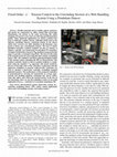
An active dancer system for reducing tension variations in wire
and sheet materials was proposed in Ref. @11#. Experimental results were reported based on an apparatus consisting of a stationary web around a dancer roller. The main drawback of the apparatus is that the results can be obtained only for a stationary web.
Construction of an active dancer system that is capable of rejecting cyclic process induced tension disturbances was reported in
Ref. @12#; the main drawback in this work is that a first-order
model for the span tension dynamics is used, which does not
reflect the tension behavior of the spans upstream/downstream of
the dancers.
In this paper, span tension dynamics for upstream and downstream spans of the active dancer roller are developed; a typical
active dancer system is considered and the governing equations
are derived. An experimental web platform has been developed to
investigate the usefulness of the active dancer system for tension
disturbance attenuation. Three types of control designs, i.e.,
proportional-derivative-integral control, internal model control,
and linear quadratic optimal control, were experimentally investigated for the active dancer system. Experimental results show that
considerable periodic tension disturbance attenuation is possible
using an active dancer system. Further, analysis of the active
dancer system model gives a structural limitation on its design;
the length of the downstream span of the dancer roller must be
smaller than the upstream span for efficient tension disturbance
attenuation using an active dancer. A numerical example is given
to illustrate this limitation.
The contributions of this work over prior work reported in literature are: ~1! development of a dynamic model of web tension
for spans upstream and downstream to the dancer roller, ~2! development of an experimental web platform containing an active
dancer system and validation of the model developed via experiments on this platform, ~3! discussion of issues related to the
design limitations of the active dancer system, and ~4! experimental evaluation of three well-known controllers for attenuation of
tension disturbances.
The remainder of the paper is organized as follows. Section 2
develops the mathematical model for web spans upstream and
downstream to the dancer roller and presents a linearized set of
equations for the developed model. Section 3 considers a general
configuration of the active dancer system and presents an inputoutput model. In Sec. 4, some considerations on the design of the
active dancer system are presented and discussed. The experimental web platform used for real-time control experiments using the
active dancer system is described in Sec. 5. Identification of the
active dancer system is given in Sec. 6. Details of the three implemented controllers and results of the experiments are discussed in
Sec. 7. Conclusions of the paper and some future work are given
in Sec. 8. A list of symbols used in the paper is also given.
Li
d
« 5 v i 2 v i « i v 2 v i21 1 v i21 « ~ i21 ! v ,
d t iv
(1)
where « i v denotes the strain in the ith web span due to velocity
variations. Throughout the paper it is assumed that the ith span
precedes the ith roller. In dancer systems, the strain in web spans
adjacent to the dancer roller is due to web velocity variations and
the dancer roller translational movement. In this section, the tension dynamics in web spans upstream and downstream to the
dancer roller are derived by noting that the net strain is equal to
the sum of the strains due to the web velocity variation and the
strain due to dancer movement.
A general dancer subsystem as shown in Fig. 2 is considered in
deriving expressions for strain in the upstream and downstream
spans due to the movement of the dancer roller. In Fig. 2, the solid
lines represent initial position of the dancer roller and the dashed
lines represent the position of the dancer when it moves by a
distance of x, that is, EE 1 5x.
To derive the strain in the upstream span, note that the initial
length of the upstream span is L 1 and the length of the span when
the dancer roll moves by a distance of x is L 1 1 d L 1 5AF 1 . Notice
that
L 1 1 d L 1 5AF 1 5AG 1 2F 1 G 1 .
(2)
From the triangle ABG 1 , AG 1 5BG 1 /sin(u11du1) and from the
triangle E 1 F 1 G 1 , F 1 G 1 5E 1 F 1 tan(u11du1)5r tan(u11du1).
Thus, Eq. ~2! can be simplified to
L 11 d L 15
BG 1
BE1EE 1 1E 1 G 1
2r tan~ u 1 1 d u 1 ! 5
sin~ u 1 1 d u 1 !
sin~ u 1 1 d u 1 !
2r tan~ u 1 1 d u 1 ! 5
2r tan~ u 1 1 d u 1 ! .
BG2EG1EE 1 1E 1 G 1
sin~ u 1 1 d u 1 !
(3)
Further notice that from the triangles ABG, EFG, and E 1 F 1 G 1 ,
the following relationships can be obtained: BG5AG sin u1
5(AF1FG)sin u15(L11r tan u1)sin u1 , EG5r/cos u1 , and E 1 G 1
5r/cos(u11du1). Thus,
2 Tension Dynamics of Web Spans Next to the Active
Dancer Roller
It is well known in the web handling literature @4,13# that the
tension dynamics of a general web span shown in Fig. 1 is given
by
Fig. 1 General web span
362 Õ Vol. 125, SEPTEMBER 2003
Fig. 2 Dancer spans: unstretched and stretched conditions
Transactions of the ASME
r
r
1x1
cos u 1
cos~ u 1 1 d u 1 !
sin~ u 1 1 d u 1 !
L 2 Ṫ 2 5 ~ EA2t r !~ V 2 2V 1 ! 1 v r ~ T 1 2T 2 !
~ L 1 1r tan u 1 ! sin u 1 2
L 11 d L 15
2r tan~ u 1 1 d u 1 ! .
1EA v r
S
D
1
EAẊ
1
2
.
X1
L 2 sin u 2 L 1 sin u 1
sin u 2
(13)
(4)
Typically, the displacement of the dancer roller is much smaller
than the length of the web span. It can be assumed that the angle
d u 1 is very small, i.e., cos du1'1 and sin du1'0. With this assumption, Eq. ~4! reduces to
x
L 1 1 d L 1 'L 1 1
.
sin u 1
Therefore, the strain induced in the upstream web span due to the
movement of the dancer roller is given by
dL1
x
« 1d 5
.
(5)
'
L1
L 1 sin u 1
By a similar argument, the strain induced in the downstream span
is
dL2
x
« 2d 5
'
.
(6)
L2
L 2 sin u 2
Noting that the strain in the upstream span is sum of the strains
due to web velocity variations and the dancer displacement, i.e.,
« 1 5« 1 v 1« 1d , we can write
d
d
d
L 1 « 1 5L 1 « 1 v 1L 1 « 1d .
(7)
dt
dt
dt
Substituting Eqs. ~1! and ~5! into Eq. ~7! results in
ẋ
d
L 1 « 15 v 12 v 1« 1v2 v 01 v 0« ov1
.
dt
sin u 1
3
Active Dancer System
The web span dynamics developed in the previous section was
for a general case of a dancer roller which is not uniform with
respect to the adjacent rollers. It is convenient to measure the
tension in the spans if the dancer roller is centrally located between the upstream and downstream rollers and the wrap angle on
the dancer roller is 180 deg, i.e., u 1 5 u 2 590 deg. Further, the
angle of wrap remains the same for the unstretched and stretched
conditions of the web spans; therefore the tension dynamics is not
nonlinear in terms of the angle of wrap on the dancer roll. With
this observation, an active dancer system as shown in Fig. 3 is
considered. This system contains web spans adjacent to the dancer
roller in the upstream and downstream directions and three rollers
including the dancer roller. All the variables shown in Fig. 3 represent variations from their reference values. It is assumed that T 0
is the upstream tension disturbance that needs to be rejected using
the active dancer.
The angular dynamics of each roller is given by
J i v̇ i 52B f i v i 1R i ~ t i11 2t i ! ,
where i50, 1, 2. Assuming that there is no slip on the rollers, the
web velocity on each roller is v i 5R i v i . Therefore, the linearized
dynamics of web velocity on each roller is given by
J i V̇ i 52B f i V i 1R i2 ~ T i11 2T i ! .
Under the assumption that the web is elastic, i.e., « i 5t i /EA, we
obtain
EA v 1 x
ẋ
L 1 ṫ 1 5EA ~ v 1 2 v 0 ! 1 ~ v 0 t 0 2 v 1 t 1 ! 1
1EA
.
L 1 sin u 1
sin u 1
(8)
For the downstream span, the total strain is the sum of the
strains due to web velocity variations and the dancer motion, i.e.,
« 2 5« 2 v 1« 2d , which gives
d
d
d
L 2 « 2 5L 2 « 2 v 1L 2 « 2d .
(9)
dt
dt
dt
(10)
Equation ~10! can be further simplified by noting that « 1 v 5« 1
2« 1d , « 2 v 5« 2 2« 2d , « 1 5t 1 /EA, and « 2 5t 2 /EA, to obtain
(15)
Using u 1 5 u 2 590 deg in Eqs. ~12! and ~13! and assuming that the
three rollers are identical, i.e., J i 5J and R i 5R, the dynamic
equations for the active dancer system shown in Fig. 3 are
b V̇ 0 52 g V 0 1 ~ T 1 2T 0 ! ,
t 1 Ṫ 1 52T 1 1T 0 1 a ~ V 1 2V 0 ! 1
(16)
a
X1 a U,
t1
b V̇ 1 52 g V 1 1 ~ T 2 2T 1 ! ,
t 2 Ṫ 2 52T 2 1T 1 1 a ~ V 2 2V 1 ! 1 a
Using Eqs. ~1! and ~6!, Eq. ~9! can be written as
ẋ
d
L 2 « 25 v 22 v 2« 2v2 v 11 v 1« 1v1
.
dt
sin u 2
(14)
2
S
(17)
(18)
D
1
1
2
X1 a U,
t2 t1
(19)
b V̇ 2 52 g V 2 1 ~ T 3 2T 2 ! ,
(20)
Ẋ5U,
(21)
2
where b 5J/R , g 5B f /R , a 5EA/ v r , t 1 5L 1 / v r , and
t 2 5L 2 / v r .
Since the value of EA is much larger than t r for most webs, the
t r term is neglected in obtaining Eqs. ~17! and ~19! from Eqs. ~12!
and ~13!.
L 2 ṫ 2 5EA ~ v 2 2 v 1 ! 1 ~ v 1 t 1 2 v 2 t 2 !
1
S
D
ẋ
v2
v1
EAx1EA
2
.
L 2 sin u 2 L 1 sin u 1
sin u 2
(11)
Equations ~8! and ~11! are nonlinear involving cross-product
terms such as v i t i . To obtain linearized equations around given
reference values of web velocity ( v r ), web tension (t r ), and
dancer displacement (x r 50), let V i 5 v i 2 v r , T i 5t i 2t r , and X
5x represent the deviations. Substituting into Eqs. ~8! and ~11!,
we obtain the linearized dynamics of web spans upstream and
downstream to the dancer roller as
L 1 Ṫ 1 5 ~ EA2t r !~ V 1 2V 0 ! 1 v r ~ T 0 2T 1 !
1
EAẊ
EA
,
v r X1
L 1 sin u 1
sin u 1
(12)
Journal of Dynamic Systems, Measurement, and Control
Fig. 3 Active dancer system
SEPTEMBER 2003, Vol. 125 Õ 363
4
Design Considerations
Combining Eqs. ~16!–~21!, the input-output dynamic model
@14# for the active dancer system is
T 2~ s ! 5
A ad ~ s !
B ad ~ s !
D ad ~ s !
U~ s !1
T 0~ s ! 1
T ~ s ! , (22)
C ad ~ s !
C ad ~ s !
C ad ~ s ! 3
where the input U(s) is the dancer translational velocity, and
A ad ~ s ! 5 ~ h s11 ! 2 ,
B ad ~ s ! 5 @ h s ~ t 1 s11 ! 12 # ,
C ad ~ s ! 5 $ @ h s ~ t 1 s11 ! 12 #@ h s ~ t 2 s11 ! 12 # 2 ~ h s11 ! % ,
S D
F
D ad ~ s ! 5 b ~ h s11 ! s1
1
t1
S
1 @ h s ~ t 1 s11 ! 12 # , s1
1
1
2
t2 t1
DG
,
11K p
where h 5J v r /EAR 2 . The input/output model has been obtained
by assuming that the roller bearing friction is negligible. A full
expression with nonzero bearing friction can be found in Ref.
@14#. Also, notice that the model is obtained under the assumption
that the moment of inertia and radius of all the rollers in the
dancer system are the same, i.e., J i 5J and R i 5R for i50, 1, 2.
Expansion of the numerator, D ad (s), and the denominator,
C ad (s), of the plant transfer function gives
C ad 5 h 2 t 1 t 2 s 4 1 h 2 ~ t 1 1 t 2 ! s 3 1 h ~ h 12 t 1 12 t 2 ! s 2 13 h s13
(23)
S D S D S
D
t1 2
h
2
1
s 1 b 31
s1 b
.
2
t2
t2
t2 t1
(24)
Notice that, if t 2 .2 t 1 , i.e., L 2 .2L 1 , then the constant term of
the numerator polynomial, D ad (s), is negative, which results in a
right-half-plane zero.
D ad 5 b h t 1 s 3 1 b h 11
It is common knowledge from classical root-locus analysis that
as the feedback gain increases, the closed-loop poles migrate to
the positions of the open-loop zeros. Since the active dancer system has a right-half-plane zero, high-gain instability will result.
Further, it is also well known that a right-half-plane zero, particularly that is on the real axis and close to zero, can cause severe
bandwidth limitations @15#. Therefore, for efficient tension disturbance attenuation using an active dancer, it is necessary to construct the active dancer system such that the downstream span
length is smaller than the upstream span length.
To illustrate the effect of the open-loop zero, root-locus plot is
employed for various span lengths. Other physical properties of
the web and rollers are kept constant, which are exactly same as
the ones used in the experiments. The closed-loop characteristic
equation with proportional feedback control, i.e., U(s)5
2K p T 2 (s), is
D ad ~ s !
50,
C ad ~ s !
(25)
where K p is the proportional gain.
Figure 4 shows the root-locus plot and the location of the openloop poles and zeros for L 1 50.9144 m (36 in.) and L 2
50.2286 m (9 in.). Figure 4 shows that the proportional gain K p
can be chosen as large as possible. Thus, the disturbance effect on
the span downstream to the dancer roll can be attenuated by an
arbitrary amount by the choice of K p . Notice that after a certain
value any increase in K p results in moving a pair of closed-loop
poles towards the imaginary axis. Hence, appropriate choice of
the gain K p must be made such that the closed-loop poles are far
away from the imaginary axis.
Figure 5 shows the root-locus plot and the location of the openloop poles and zeros for L 1 5L 2 50.2286 m (9 in.). In this case,
there is a pair of complex-conjugate open-loop poles very close to
a pair of complex-conjugate zeros. Thus, any choice of the gain
cannot move this pair of open-loop poles further to the left-half-
Fig. 4 Root locus plot for L 1 Ì L 2
364 Õ Vol. 125, SEPTEMBER 2003
Transactions of the ASME
plane away from the imaginary axis. The effectiveness of the active dancer to attenuate tension disturbances is reduced.
The root-locus plot and location of open-loop poles and zeros
for L 1 50.2286 m (9 in.) and L 2 50.9144 m (36 in.) is shown in
Fig. 6. In this case, the root-locus crosses the imaginary axis and
enters the right-half plane when K p exceeds a certain value. For
the numerical example considered, as shown in Fig. 6, a branch of
the root locus moves to the right-half plane for a very small value
of K p .
Root-locus plots obtained by varying b and h did not show any
appreciable change in the form of the root locus. In all these cases,
a small value of K p rendered the closed-loop system unstable for
Fig. 5 Root locus plot for L 1 Ä L 2
Fig. 6 Root locus plot for L 1 Ë L 2 Õ2
Journal of Dynamic Systems, Measurement, and Control
SEPTEMBER 2003, Vol. 125 Õ 365
the case of L 2 .2L 1 . Notice that variations of b and h in the
input-output model reflect variations of web and roller properties,
E, A, J, R, B f , etc.
An intuitive explanation of the effect of span length is given in
the following. Assuming that the web is mostly elastic, it is common practice in the web handling community to model a web span
as an elastic spring with a spring constant K n 5E n A n /L n . The
spring constants of the upstream and the downstream web spans to
the dancer roller are K 1 5EA/L 1 and K 2 5EA/L 2 , respectively,
as shown in Fig. 7.
If L 1 >L 2 , K 1 <K 2 , then any motion of the dancer roller results in larger tension variations in span 2 than in span 1. Thus,
rejection of periodic disturbances from the spans upstream of the
dancer roller into the spans downstream of the dancer roller is
possible in this case. If L 1 ,L 2 /2, K 1 .2K 2 , then periodic dancer
motion induces larger tension disturbances into the upstream span
than it rejects in the downstream span due to feedback of tension
T2 .
5
Experimental Web Platform
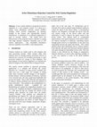
A sketch of the open-architecture experimental web platform
together with an active dancer system is shown in Fig. 8. Pictures
of the complete experimental platform and the active dancer system are shown in Figs. 9 and 10, respectively. In the active dancer
system, shown in Fig. 10, the bottom most roller is the active
dancer roller. The web platform mainly consists of an endless web
line with a number of rollers, an active dancer system, web guides
for maintaining lateral position. The term endless web line refers
to a web line without unwind and rewind rolls. This type of platform mimics most of the features of a process section of a web
processing line.
Mechanical components used in the platform include 16 idle
rollers, a master speed roller with a nip roller, an electric motor,
and a passive dancer system with a pneumatic cylinder. The width
of each roller is 0.2032 m ~8 in.! and the diameter is 0.127 m ~5
in.!, except for the master speed roller, which has a diameter of
0.254 m ~10 in.!. A nip roller on the master speed roller is used to
reduce slip during startup. The master speed roller sets the desired
transport velocity of the web. Air pressure in the pneumatic cylinder of the passive dancer roll is used to set the desired reference
web tension. The active dancer system consists of an electromechanical actuator, a guide way with the dancer roller mounted on
it, and load cells on the idle roller downstream of the dancer roller.
A Pentium 450-MHz computer with a Keithley DAS 1601 digital
data acquisition board is used for real-time control experiments. A
control sampling period of 5 ms is used in all the experiments.
The measured signals on the experimental web platform ~see
sketch in Fig. 8! include the velocity of the web measured at the
roller immediately downstream of the master speed roller, tension
from both load cells shown in Fig. 8, translational velocity of the
dancer roller, and lateral position of the web downstream of the
guide system. These signals are used during system identification,
control, and monitoring.
A transparent polyester film is used as the web material, which
has the following properties: E54.1363109 N/m2 (63105 PSI),
A50.0819 m2 (1.2731024 in.2 ), J50.0282 kg m2 ~96.21 lb in.2 ),
and R563.5 mm (2.5 in.). The length of the web spans upstream
and downstream to the dancer roller are 36 and 9 in., respectively.
Periodic tension disturbances upstream of the dancer roller are
created by introducing an out-of-round roll surface into an idle
roller in the web line as shown in Fig. 8. Load cells that are
mounted on the roller immediately downstream of the out-ofround idle roller measure the amount of tension disturbance that is
being generated. The fundamental frequency of the periodic tension disturbance for a given out-of-round roller surface increases
with increase in web speed.
Fig. 9 Picture of the web platform
Fig. 7 Interpretation of the effect of span lengths
Fig. 8 Sketch of the experimental web platform
366 Õ Vol. 125, SEPTEMBER 2003
Fig. 10 Picture of the active dancer system
Transactions of the ASME
6
System Identification
T 2 ~ k ! 5G ~ z 21 ! U ~ k ! 1H ~ z 21 ! e ~ k ! ,
The transfer function @ T 2 (z)/U(z) # from the dancer velocity to
the tension in the span downstream to the dancer roller is considered for identification. The discrete-time equivalent of the
continuous-time input-output model, Eq. ~22!, with a sampling
period of 5 ms, is
4.233z 3 212.55z 2 112.41z24.089
22
T 2 ~ z ! 510
z 4 23.966z 3 15.897z 2 23.897z10.9659
110
U~ z !
z 4 23.966z 3 15.897z 2 23.897z10.9659
11026
6.812z 3 26.828z 2 26.687z16.702
4
3
H ~ z 21 ! 5C ~ z 21 ! /D ~ z 21 ! ,
2
z 23.966z 15.897z 23.897z10.9659
F ~ z 21 ! 511 f 1 z 21 1¯1 f n f z 2n f ,
T 0~ z !
T 3~ z ! .
(26)
In the above conversion, we have used the same numerical values
for parameters as given in Sec. 5 with a reference web velocity of
1.266 m/s ~250 FPM!. To experimentally identify the transfer
function @ T 2 (z)/U(z) # , the web is run at a speed of 1.266 m/s
~250 FPM!, and a pseudorandom signal is used as the input for the
dancer roller velocity. The dancer velocity input U(k) and variations in tension in the span downstream to the dancer roller T 2 (k)
are acquired at each sampling period. The Box-Jenkins model
@16#, given by the following equation, is used to represent the
relation between T 2 (k) and U(k):
Ĝ ~ z ! 5
G ~ z 21 ! 5B ~ z 21 ! /F ~ z 21 ! ,
B ~ z 21 ! 5b 0 1b 1 z 21 1¯1b n b z 2n b ,
9.537z 3 29.635z 2 29.324z19.421
25
(27)
where
C ~ z 21 ! 511c 1 z 21 1¯1c n c z 2n c ,
D ~ z 21 ! 511d 1 z 21 1¯1d n d z 2n d ,
e ~ k ! is white noise,
and
z 21 represents the unit delay operator.
The term H(z 21 )e(k) is included to account for the terms T 0 , and
T 3 in Eq. ~22! and other disturbances affecting the tension T 2 .
Using this model and the data obtained, generalized partial autocorrelation function ~GPAC! technique @17# is used to estimate the
orders of the polynomials B(z 21 ), F(z 21 ), C(z 21 ), and D(z 21 );
these orders are found to be n b 53, n f 510, n c 51, and n d 51. The
coefficients, b i , f i , c i , were estimated using the LevenbergMarquardt algorithm @18#. The Appendix gives a step-by-step procedure of the identification technique used to arrive at the inputoutput model. The identified transfer function from the dancer
roller velocity input to the downstream tension is
T 2~ z !
20.0173z 3 10.0359z 2 10.1257z20.1351
5 10
.
U ~ z ! z 21.161z 9 20.9063z 8 10.8857z 7 10.9595z 6 20.2485z 5 20.9768z 4 10.1006z 3 10.7366z 2 20.3341z20.0557
(28)
The relative degree of the experimentally identified transfer function, Eq. ~28!, is much higher than the theoretical model, Eq. ~22!.
This can be attributed to the fact that the dynamics of the motor,
the platform containing the dancer roller, and of the load cell are
not taken into account in the theoretical model. Since such highorder transfer functions are not amenable for analysis, model reduction technique using Bilinear Schwartz approximation @19# is
used to obtain a lower-order approximation of Ĝ(z). The fourthorder Bilinear Schwartz approximation of Eq. ~28! is
Ĝ 4 ~ z ! 5
0.05462z 3 20.2269z 2 10.3071z20.1335
z 4 23.103z 3 13.581z 2 21.773z10.2948
.
an internal model based controller ~IMC!, and a linear quadratic
regulator ~LQR!. The internal model based controller consists of a
proportional controller and an internal model of sinusoidal tension
disturbance with a known frequency and unknown amplitude. The
frequency of the tension disturbance is obtained by taking a fastFourier transform ~FFT! of the tension signal obtained from the
(29)
The Bode plots of the experimentally identified transfer function
Ĝ(z), the reduced fourth-order model Ĝ 4 (z), and the theoretical
model are shown in Fig. 11. From the Bode plots, it can be observed that the reduced fourth-order model is very similar to the
original tenth-order identified model. Further, it can also be observed that the behavior of the theoretical model is similar to that
of the identified model, except for variations in the low-frequency
gain and the corner frequency, in the frequency range of interest,
which is up to 50 rad/s ~8 Hz!. Also, notice that the identified
model has a pair of under damped poles around 80 rad/s ~13 Hz!
frequency region, which are not reflected in the theoretical model;
these poles may reflect resonant conditions of the active dancer
structure, load cells, or the experimental platform structure.
7
Implemented Controllers and Experimental Results
Three types of controllers were implemented for the active
dancer system: a proportional-integral-derivative controller ~PID!,
Journal of Dynamic Systems, Measurement, and Control
Fig. 11 Theoretical and identified Bode plots
SEPTEMBER 2003, Vol. 125 Õ 367
load cell located upstream of the dancer roller. A description of the
design of three controllers implemented is presented in the following.
The pulse transfer function of the PID controller that is experimentally implemented is
G c~ z ! ª
Ki
U~ z !
5K p 1
1K d ~ 12z 21 !
T 2~ z !
12z 21
5
K 1 2K 2 z 21 1K 3 z 22
12z 21
,
(30)
where K p , K i , and K d are proportional, integral, and derivative
gains, respectively, and K 1 5K p 1K i 1K d , K 2 5K p 12K d , and
K 3 5K d . The gains K 1 , K 2 , and K 3 were chosen to place the
closed-loop poles of the active dancer system with the following
design requirements: percentage peak overshoot of less than 10%
and the settling time of less than 1 s. This design process was
carried out using the ‘‘rltool’’ utility in MATLAB. The following
gain values were obtained: K p 51.932, K d 50.8063, and K i
52.1099. Figure 12 shows the performance of the PID controller;
the top two plots correspond to the measured periodic tension
disturbance and its FFT, and the bottom two plots show the measured tension error and its FFT when the active dancer roller is
under PID control. Notice that the frequency of tension disturbance is about 25.13 rad/s ~4 Hz! when the line is running at a
reference speed of 1.772 m/s ~350 FPM!.
In the internal model based type of controller, a proportional
controller is augmented with an internal model of the disturbance;
the classical internal model principle is used. The disturbance
frequency, q, is measured by taking an FFT of the measured ten-
Fig. 12 Tension with out-of-round idle roller „disturbance and
PID control…; v r Ä1.772 mÕs „350 FPM…, t r Ä160.14 N „36 lbf…
368 Õ Vol. 125, SEPTEMBER 2003
sion signal from the load cell prior to implementing the controller.
The following is the structure of the IMC controller that was
implemented:
G c~ z ! 5
K p 1z 21 K imc sin~ q T s !
122z 21 cos~ q T s ! 1z 22
,
(31)
where K p is the proportional gain, T s is the sampling period, and
K imc is the tunable gain to compensate for the unknown amplitude
of the periodic tension disturbance. Using the ‘‘rltool’’ utility of
MATLAB, the gains K p and K imc were calculated for each of the
web speeds to place the closed-loop poles such that the settling
time is less than 1 s and percentage overshoot is less than 10%.
The following gains were obtained and used in the experiments:
K p 50.04607 and K imc 50.04607.
In the experimental platform shown in Fig. 9, tension disturbance is created by an out-of-round roller in the web path. Thus,
the disturbance frequency is proportional to the web speed. Experiments were conducted at various web speeds ~thus, different
known disturbance frequencies! and a representative result is
shown in Fig. 13; this also corresponds to a line speed of 1.772
m/s ~350 FPM! which results in a disturbance frequency of about
25.13 rad/s ~4 Hz!. The top two plots of Fig. 13 show the controlled tension with IMC controller and the FFT of the controlled
tension, respectively.
To formulate a traditional stationary LQR problem for the active dancer system, we consider the state space equations obtained
from the input-output model given by Eq. ~26!. The state space
equations can be expressed in the matrix form as
j ~ k11 ! 5G j ~ k ! 1H u U ~ k ! ,
(32)
y ~ k ! 5C j ~ k ! .
Fig. 13 Tension with out-of-round idle roller „IMC and LQR…;
v r Ä1.772 mÕs „350 FPM…, t r Ä160.14 N „36 lbf…
Transactions of the ASME
The following performance index is used to obtain the optimal
control input:
`
J5
1
@ y 2 ~ k ! 1R lqr U 2 ~ k !# ,
2 k50
(
(33)
where R lqr is the weighting factor that penalizes control input
magnitude. The control input that results from minimizing the
above performance index is a state feedback controller of the form
U(k)52K j (k). A Luenberger observer was used to estimate the
state variables based on the measured tension. A control weighting
factor value of 0.1, i.e., R lqr 50.1, was used; any value smaller
than this resulted in the control effort being very large and exceeding the active dancer motor velocity limits. The control and observer gain vectors that were computed off-line and used in the
experiments were K51023 (0.0011306,0.77836,53.584,207.95)
and L5(20.96586,3.8969,25.8833,3.773), respectively.
Experiments were conducted at various web speeds and a
representative result for the reference web speed of 1.772 m/s
~350 FPM! for the LQR controller is shown in the bottom
two plots of Fig. 13; the bottom two plots show the controlled
tension with LQR controller and the FFT of the controlled tension,
respectively.
A summary of the amount of tension disturbance magnitude
reduction for PID, IMC, and LQR controllers for four different
web speeds, 1.013 m/s, 1.266 m/s, 1.519 m/s, 1.772 m/s ~200
FPM, 250 FPM, 300 FPM, and 350 FPM! is shown in Fig. 14.
The summary shown in Fig. 14 indicates that all the three controllers give good attenuation of the periodic tension disturbance using the active dancer. Notice that at the low speed of 1.012 m/s
~200 FPM!, the attenuation level of all three controllers is similar
but as the speed is increased the attenuation level is more for the
IMC and the LQR controllers. It is not clear from a number of
experiments as to why there is a variation of tension attenuation
levels at different speeds, and why the tension attenuation level
drops from 1.266 to 1.519 m/s whereas it increases from 1.519 to
1.772 m/s. We believe that one possible reason for this could be
due to the endless web line that is used in the experiments; in an
endless web line the same web loops around in the platform. We
have assumed that there is no propagation of tension in the upstream direction from the web span where tension disturbances
are created; this is true only when there is not slip on the rollers.
We plan to investigate this further after incorporating unwind/
rewind stands into the current experimental platform.
Experimental results show that the active dancer system is effective in attenuating periodic tension disturbances. The distur-
bance rejection capability of the active dancer system is limited
only by the bandwidth limitation of the actuator as opposed to the
passive dancer or an inertia compensated dancer which are known
to have considerable resonance problems.
8
Conclusions and Future Work
In this paper, a mathematical model of an active dancer system
which can be used for periodic tension disturbance attenuation has
been developed. An experimental web platform with an active
dancer system has been developed to conduct real-time experiments. Data collected from an extensive set of experiments validate the usefulness of an active dancer in attenuation of periodic
web tension disturbance in a web process line. Further, analysis of
the model reveals a structural limitation on the design of the active dancer system, which is the ratio of the downstream to upstream web span length with respect to the active dancer roller
must be less than 2 for tension attenuation using an active dancer.
Future research will focus on incorporating the active dancer
mechanism in an unwind/rewind web process line. This work assumed that there is no slip of the web on the dancer roller, which
may not be the case at high web speeds and large amplitude periodic tension disturbances. Our future work will also focus on the
study of slip on the dancer roller. In this paper, we have investigated the effectiveness of the active dancers for steady operating
speeds and tensions, that is, we have considered the linearized
system. Future work will include design of the controllers, such as
iterative learning controllers @20,21# and robust adaptive controllers, for the complete nonlinear model that accounts for transients
during startup and shutdown conditions in web process lines.
Acknowledgments
The authors acknowledge the support of the Web Handling Research Center, the Oklahoma Center for Advancement of Science
and Technology under Project No. AR982-021, and the National
Science Foundation under Grant No. CMS 9982071.
Nomenclature
A
Bf
E
J
R
vr
tr
t
Li
ti
vi
Ti
Vi
ti
Ki
X
5
5
5
5
5
5
5
5
5
5
5
5
5
5
5
5
U
a,b,g,h
«i
« iv
« id
5
5
5
5
5
u1 , u2 5
Cross-sectional area of web
Bearing friction
Modulus of elasticity
Polar moment of inertia of roller
Radius of a roller
Reference web velocity
Reference web tension
Time
Length of the ith web span
Tension in the ith web span
Web velocity on the ith roller
Change in tension from the reference
Change in web velocity from the reference
Time constant of a web span (L i / v r )
Web span spring constant (EA/L i )
Change in linear displacement of the dancer roll
from the reference
Dancer translational velocity input
System constants (EA/ v r ,J/R 2 ,B f /R 2 , b / a )
Strain in the ith web span
Strain due to velocity variation in the ith web span
Strain due to dancer displacement in the ith web
span ~applies only to spans next to the dancer roll!
Wrap angles on upstream and downstream side of
dancer roll
Appendix: Identification Procedure
The dynamics between the tension t 2 and the dancer velocity u
is described in the form of the Box-Jenkins Model as
Fig. 14 Summary of tension disturbance reduction
Journal of Dynamic Systems, Measurement, and Control
T 2 ~ k ! 5G ~ z 21 ! U ~ k ! 1H ~ z 21 ! e ~ k ! .
(34)
SEPTEMBER 2003, Vol. 125 Õ 369
To estimate the transfer function we go through the following
steps: ~1! Estimate the impulse response for G(z), ~2! Find the
orders of the numerator and denominator in the transfer function
G(z), and ~3! Estimate the coefficients in the numerator and the
denominator polynomials.
To estimate the impulse response, ĝ(k), of the transfer function
G(z), assume that the input u(k) and the white noise e(k) are not
correlated and ĝ(k)50 for some k.K, then
The above equations can be written in matrix form as
F
R u~ 0 !
R u~ 1 !
¯
R u~ K !
R u~ 1 !
R u~ 0 !
¯
R u ~ K21 !
:
:
:
:
R u~ K !
R u ~ K21 !
¯
R u~ 0 !
(37)
K
y ~ t !5
(
ĝ ~ i ! u ~ t2i ! .
(35)
i50
Multiplying both sides of Eq. ~35! by u(t2k) and taking expectation and simplifying yields
K
R uy ~ k ! 5
( ĝ ~ i ! R ~ k2i ! ,
i50
u
k50,1,2, . . . ,K.
U
U
(36)
ĝ ~ j22 !
¯
ĝ ~ j2k11 !
ĝ ~ j !
ĝ ~ j !
ĝ ~ j21 !
¯
ĝ ~ j2k12 !
ĝ ~ j11 !
:
:
:
¯
¯
ĝ ~ j22 !
ĝ ~ j2k11 !
ĝ ~ j1k21 !
.
ĝ ~ j2k !
ĝ ~ j !
ĝ ~ j21 !
¯
ĝ ~ j2k12 !
ĝ ~ j2k11 !
:
:
:
:
:
ĝ ~ j1k22 !
ĝ ~ j1k23 !
¯
ĝ ~ j22 !
ĝ ~ j21 !
ĉ k 5 @ b̂ 0 , . . . ,b̂ n b , f̂ 1 , . . . , f̂ n f ,ĉ 1 , . . . ,ĉ n c ,d̂ 1 , . . . ,d̂ n d # T .
(39)
The estimated output and residue of estimation can be computed
as
ŷ ~ t u ĉ k ! 5Ĥ 21 Ĝ ~ q ! u ~ t ! 1 @ 12Ĥ 21 # y ~ t ! ,
] ĉ k ~ 1 !
] ĉ k ~ 2 !
] ŷ ~ t u ĉ k !
] ĉ k ~ n !
G
,
(41)
where n is the total number of parameters to be estimated. Each
element in this vector can be computed numerically. The algo370 Õ Vol. 125, SEPTEMBER 2003
rithm terminates when a tolerance specified by J gradmin is met.
This algorithm also requires an initial value m 0 of m and a multiplier ~divisor! n to account for fast ~slow! convergence. The
Levenberg-Marquardt algorithm is
~1! Input c 0 , minimal gradient J gradmin , m 0 , n, u(t), and
y(t).
~2! Repeat the following starting with k50.
~3! Set k5k11 and m k11 5 m k / n .
~4! Compute J( ĉ k ), «( ĉ k ).
~5! Solve
for
D ĉ k
from
@ J T ( ĉ k )J( ĉ k )1 m k I # D ĉ k
52J T ( ĉ k )«( ĉ k ).
~6! Update the parameter vector ĉ k11 5 ĉ k 1D ĉ k .
~7! If F( ĉ k11 )>F( ĉ k ), set m k 5 m k * n and go to step 5. Otherwise continue.
~8! Set m k11 5 m k .
~9! If i 2J T ( ĉ k11 )«( ĉ k11 ) i ,J gradmin or m k . m max , terminate
the computation. Otherwise go to step 3.
Complete details of the Levenberg-Marquardt algorithm can be
found in Ref. @18#.
References
Now, we consider the cost function defined by F( ĉ k )
N
5 ( t51
« T ( ĉ k )«( ĉ k ) where N is the total number of data points,
can be considered for minimization. The Levenberg-Marquardt
algorithm uses a gradient search method which requires the computation of the vector J( ĉ k ) defined as
¯
(38)
(40)
« ~ ĉ k ! 5y ~ t ! 2ŷ ~ t u ĉ k ! .
] ŷ ~ t u ĉ k ! ] ŷ ~ t u ĉ k !
:
U
U
:
ĝ ~ j1k23 !
ĝ ~ j22 !
As shown in Ref. @21#, the GPAC function has the property that
n
j
is of the form 0/0 for
f kkb 50 for k5n f 11,n f 12, . . . , and f kk
j5n b 11,n b 12, . . . , and k5n f 11,n f 12, . . . . This property can
be used to identify the orders of the numerator and the denominator polynomials of the transfer function. In a similar way, we
can find the orders of the numerator and the denominator, n c and
n d , of the transfer function H(z).
Once the orders of the numerator and the denominator of the
transfer function are known, the Levenberg-Marquardt algorithm
was used to estimate the unknown coefficients, b 0 , b 1 , . . . ,b n b ,
f 1 , f 2 , . . . , f n f , c 1 , c 2 , . . . ,c n c , and d 1 , d 2 , . . . ,d n d . To this
end, define the estimate of the parameter vector in the kth iteration
as
F
From Eq. ~37! ĝ(i) for i50,1, . . . ,K, can be computed. In the
experiments K was chosen to be 50.
To find the orders of the numerator and the denominator polynomials (n b and n f ) of the transfer function G(z), the generalized
partial autocorrelation ~GPAC! function method as given in Refs.
j
@17#, @21# is used. The GPAC function f kk
is defined as
ĝ ~ j21 !
ĝ ~ j1k22 !
j
f kk
5
ĝ ~ j21 !
J ~ ĉ k ! 52
GF G F G
ĝ ~ 0 !
R uy ~ 0 !
ĝ ~ 1 !
R uy ~ 1 !
5
.
:
:
ĝ ~ K !
R uy ~ K !
@1# Campbell, D. P., 1958, Dynamic Behavior of the Production Process, Process
Dynamics, John Wiley and Sons, Inc., New York, first edition.
@2# Grenfell, K. P., 1963, ‘‘Tension Control on Paper-Making and Converting Machinery,’’ IEEE 9-th Annual Conference on Electrical Engineering in the Pulp
and Paper Industry, Boston, MA, pp. 20–21.
@3# King, D., 1969, ‘‘The Mathematical Model of a Newspaper Press,’’ Newspaper
Techniques, pp. 3–7.
@4# Brandenburg, G., 1977, ‘‘New Mathematical Models for Web Tension and
Register Error,’’ International IFAC Conference on Instrumentation and Automation in the Paper, Rubber, and Plastics Industry, Vol. 1, pp. 411– 438.
@5# Shelton, J. J., 1986, ‘‘Dynamics of Web Tension Control With Velocity or
Torque Control,’’ Proceedings of the American Control Conference, Seattle,
WA, pp. 1423–1427.
@6# Shin, K. H., 1991, ‘‘Distributed Control of Tension in Multi-Span Web Transport Systems,’’ Ph.D. thesis, Oklahoma State University, Stillwater, Oklahoma.
Transactions of the ASME
@7# Young, G. E., and Reid, K. N., 1993, ‘‘Lateral and Longitudinal Dynamic
Behavior and Control of Moving Webs,’’ ASME J. Dyn. Syst., Meas., Control,
115, pp. 309–317.
@8# Wolfermann, W., 1995, ‘‘Tension Control of Webs, a Review of the Problems
and Solutions in the Present and Future,’’ Proceedings of the Third International Conference on Web Handling, pp. 198 –229.
@9# Shelton, J. J., 1999, ‘‘Limitations to Sensing of Web Tension by Means of
Roller Reaction Forces,’’ Proceedings of the Fifth International Conference on
Web Handling.
@10# Reid, K. N., and Lin, K. C., 1993. ‘‘Dynamic Behavior of Dancer Subsystems
in Web Transport Systems,’’ Proceedings of the Second International Conference on Web Handling, pp. 135–146.
@11# Kuribayashi, K., and Nakajima, K., 1984, ‘‘An Active Dancer Roller System
for Tension Control of Wire and Sheet,’’ Proceedings of the 9th Triennial
World Congress of IFAC, Budapest, Hungary, pp. 1747–1752.
@12# Rajala, G. J., 1995, Active Dancer Control for Web Handling Machine, M.S.
thesis, University of Wisconsin, Madison, WI.
@13# Pagilla, P. R., Perera, L. P., and Dwivedula, R. V., 2001, ‘‘The Role of Active
Dancers in Tension Control of Webs,’’ Proceedings of the Sixth International
Conference on Web Handling.
Journal of Dynamic Systems, Measurement, and Control
@14# Perera, L. P., 2001, ‘‘The Role of Active Dancers in Tension Control of Webs,’’
M.S. thesis, Oklahoma State University, Stillwater, OK.
@15# Skogestad, S., and Postlethwaite, I., 1996, Multivariable Feedback Control:
Analysis and Design, John Wiley and Sons, New York.
@16# Ljung, L., and Soderstrom, T., 1983, Theory and Practice of Recursive Identification, MIT Press, Cambridge, MA.
@17# Woodward, W. A., and Gray, H. L., 1981, ‘‘On the Relationship Between the S
Array and the Box-Jenkins Method of ARMA Model Identification,’’ J. Am.
Stat. Assoc., 76, pp. 579–587.
@18# Hagan, M., Demuth, H., and Beale, M., 1996, Neural Network Design, PWS
Publishing, Boston, MA.
@19# Hsieh, C.-H., and Hwang, C., 1990, ‘‘Model Reduction of Linear DiscreteTime Systems Using Bilinear Schwarz Approximation,’’ Int. J. Syst. Sci., 21,
pp. 33– 49.
@20# Moore, K. L., Dahleh, M., and Bhattacharya, S. P., 1992, ‘‘Iterative Learning
Control: A Survey and New Results,’’ J. Rob. Syst., 9, pp. 563–594.
@21# Abdul-Al-Nadi, D. I., 1991, ARMA Order Determination, M.S. thesis, Oklahoma State University.
SEPTEMBER 2003, Vol. 125 Õ 371
Academia.edu no longer supports Internet Explorer.
To browse Academia.edu and the wider internet faster and more securely, please take a few seconds to upgrade your browser.
Periodic Tension Disturbance Attenuation in Web Process Lines Using Active Dancers
Journal of Dynamic Systems, Measurement, and Control, 2003
...Read more
Related Papers

Decision and Control, 2001 …, 2001
Download
2009 American Control Conference, 2009
Download

An Active Disturbance Rejection Approach to Tension and Velocity Regulations in Web Processing Lines
2007 IEEE International Conference on Control Applications, 2007
Download

Download

Download

IEEE Transactions on Control Systems Technology, 2000
Download

2013 15th European Conference on Power Electronics and Applications (EPE), 2013
Download


Download


Revista española de la opinión pública, 1970
Download
