US 20140340470A1
(19) United States
(12) Patent Application Publication (10) Pub. No.: US 2014/0340470 A1
(54)
SYSTEMAND METHODS FOR VIDEO
IMAGE PROCESSING
Publication Classification
(51)
(71) Applicants: Timothy William Perez, Albuquerque,
NM (US); Marios Stephanou Pattichis,
Albuquerque, NM (US); Yuebing Jiang,
Albuquerque, NM (US)
(52)
H04N 5/232
G06T3/40
U.S. C.
(2006.01)
(2006.01)
CPC .......... H04N 5/23238 (2013.01); G06T3/4007
USPC ............................................................ 348/36
(21) Appl. No.: 14/069,153
Oct. 31, 2013
Related U.S. Application Data
Provisional
application No. 61/825,183, filed on May
(60)
20, 2013.
Int. C.
(2013.01)
(72) Inventors: Timothy William Perez, Albuquerque,
NM (US); Marios Stephanou Pattichis,
Albuquerque, NM (US); Yuebing Jiang,
Albuquerque, NM (US)
(22) Filed:
Nov. 20, 2014
(43) Pub. Date:
Perez et al.
ABSTRACT
(57)
Certain embodiments of the present invention include a sys
tem and methods for providing a video image display tech
nology with separate video perspective displays. Each per
spective display may be tailored and adapted in real-time to
the differing roles of each user, e.g., one or more medical
professionals of a Surgical team. As an example, one video
perspective display may be a panoramic perspective display
for a primary Surgeon and a second video perspective may be
a detailed perspective display for the Surgical assistant.
Image
Management
Component
Camera
Source
Component
102
104.
Output
Component
106
�Patent Application Publication
euºeO ?OunS
Nov. 20, 2014 Sheet 1 of 10
qnd?nO
?uêodO
||
90
US 2014/0340470 A1
�Patent Application Publication
Nov. 20, 2014 Sheet 2 of 10
<C
O
O
3.
US 2014/0340470 A1
�Patent Application Publication
puOÐS ?nd?nO
euêeO ?OJnoS
Nov. 20, 2014 Sheet 3 of 10
US 2014/0340470 A1
�Patent Application Publication
Nov. 20, 2014 Sheet 4 of 10
US 2014/0340470 A1
pu09S Áue:Odal 36ejo?S
89"$DIE
�Patent Application Publication
ZOZ
Nov. 20, 2014 Sheet 5 of 10
US 2014/0340470 A1
�Patent Application Publication
Nov. 20, 2014 Sheet 6 of 10
US 2014/0340470 A1
89
�Patent Application Publication
Nov. 20, 2014 Sheet 7 of 10
US 2014/0340470 A1
�Patent Application Publication
Nov. 20, 2014 Sheet 8 of 10
009
JOS90jc&
909
US 2014/0340470 A1
�Patent Application Publication
Nov. 20, 2014 Sheet 9 of 10
pnOR
pnOR
US 2014/0340470 A1
�Patent Application Publication
Nov. 20, 2014 Sheet 10 of 10
US 2014/0340470 A1
CO
O
s s s s
�Nov. 20, 2014
US 2014/0340470 A1
SYSTEMAND METHODS FOR VIDEO
IMAGE PROCESSING
CROSS REFERENCE TO RELATED PATENTS
0001. This application claims the benefit of U.S. Provi
sional Application No. 61/825,183 filed May 20, 2013, which
is incorporated by reference herein in its entirety.
FIELD OF THE INVENTION
0002 The invention relates generally to displaying video
images from a single source.
BACKGROUND OF THE INVENTION
0003 Video imaging technology permits capturing and
displaying images of a target, possibly via an input/output
interface Such as an output component. Examples of an output
component include a screen, monitor, touchscreen, speaker,
light-emitting diode display, or projector and/or receiving
element for projector (including, e.g., a wall projector, over
head projector, or head-mounted projector Such as a Google
Glass unit).
0004 Such video imaging technology has many applica
tions. For example, Video imaging may be used for security
functions (e.g., video Surveillance of residences, commercial
locations, warehouses, valuable objects, or other objects or
location areas), observation functions (e.g., observing a
nanny, housekeeper, or pet, possibly remotely), educational
functions (e.g., transmitting lectures or discussions in dis
tance education programs), business functions (e.g., virtual
meetings or communication with remote customers or col
leagues), and media functions (e.g., broadcasting news, tele
vision programs, or movies). In addition, video imaging tech
nology may be used for tracking functions (e.g., monitoring
the quantity of goods or services rendered, quantity of people
that enter or exit a location area, studying an experimental
object, or progress of a task), healthcarefunctions (e.g., facili
tating Surgical examination or operations using Small inci
sions and Small camera systems), and other communication
functions.
0005 Certain known video camera systems are configured
to convey video images to an output component generally in
real-time. There may be advantages to such systems. For
example, if a security officer reviews surveillance video
images generally in real-time and perceives a threat to a
target, the security officer may be able to intervene and pos
sibly prevent or minimize harm to the target. Also, if a busi
ness person receives meeting video images generally in real
time, that business person can contribute to the meeting,
possibly by transmitting his or her own video images, sending
an email or text notification, or participating by telephone. In
addition, if a health care professional is performing a Surgical
examination or operation using a small camera to perceive the
Surgery site, the health care professional may rely on the
real-time video images to perceive how and where to manipu
late the Surgical instruments.
0006 When performing certain functions, there may be a
need to provide two perspectives of a target in real-time. For
example, a security officer may wish to perceive two perspec
tives of the same target to permit perceiving both a close-up
perspective of the target (e.g., to identify a crack in a glass
case around a valuable object) and a wide-view perspective of
the target (e.g., possibly to observe which direction an
offender went after cracking the glass case). A business per
son may wish to perceive two perspectives of a meeting room,
specifically, a close-up perspective of a specific meeting par
ticipant and a wide-view perspective of the entire room pos
sibly to permit recognizing certain dynamics of the entire
meeting. Also, when two or more health care professionals
are performing the Surgical examination or operation, each
professional may need a different perspective of the Surgical
site to perform their job optimally.
0007 Certain known imaging systems and procedures are
configured to display two identical perspectives or two very
similar perspectives of the same target. Clearly, Such systems
do not meet the need for simultaneously providing one close
up perspective and one wide-view perspective.
0008. Additional imaging systems have been developed to
provide two different perspectives in real-time. One such
conventional imaging system permits showing the same per
spective in two different displays, e.g., Internet browsers.
Then, each user can manually adjust the Zoom level of each of
the two perspectives according to his or her needs. However,
for certain functions, the user may be multi-tasking (e.g.,
manipulating Surgical tools or taking notes while perceiving
the video images of the target), which renders manually
adjusting the Zoom level of the video image challenging. In
addition, the quality of the Zoomed-in image often is poor.
0009. Another conventional system for providing two dif
ferent perspectives simultaneously provides higher resolu
tion images by using two cameras, one for capturing each
perspective. However, Such two-camera systems may be cost
prohibitive, size-limiting if access to the target is restricted, or
possibly detrimental to the observation if the second camera
intensifies the observer effect. For purposes of this applica
tion, the term “observer effect” means the changes in the
target that may be caused observing the target. Examples of
the observer effect known in the art include the Heisenberg
effect and Hawthorne effect.
0010. Other attempts to provide video images split into
two different perspective displays of a target have been unre
liable, computationally expensive, or otherwise resulted in
exceedingly low quality resolution of each perspective dis
play.
0011 Clearly, there is a demand for a system and methods
for automatically and reliably providing two high-quality
perspective displays of a target from a single camera Source
generally in real-time. The present invention satisfies this
demand.
SUMMARY OF THE INVENTION
0012 Certain embodiments of the present invention are
configured to provide two different perspective displays of a
target from a single video image generated by a single camera
Source component. Each of the two or more perspective dis
plays is a type of output video image configured to be shown
by an output component.
0013 For purposes of this application, the term “target'
means that which is the subject of interest, the subject that the
user intends to convey, or a Subject within the angle of view of
the camera source component. For example, a target may be
a single object, a portion of an object, a group of objects, a
location area, a specific location, or a site inside of an object
(e.g., a site inside the body of an organism).
0014 For purposes of this application, the term “video
image' indicates any type of moving image (typically made
up of a series of still images (e.g., video frames) flashed so
quickly that, because of persistence of vision, appear as a
�Nov. 20, 2014
US 2014/0340470 A1
moving image). A video image may be stored, for example, as
a video file. A video file is a set of information that when read
by a computer processor causes an output component in com
munication with the computer processor to display a video
image. Examples of video image files include BMP file type
for still images, MPEG-1 file type for digital video, MPEG-2
file type for digital video, and JPEG file type for still images.
0015. In certain embodiments, a single camera source
component captures video image of a target. By processing
the video image from that single camera source component,
the video image is converted into one or more different per
spective displays. For purposes of this application, the present
invention is discussed in reference to systems and methods
configured to produce two perspective displays, but the dis
cussion is merely exemplary. The present invention also may
be configured to produce only one perspective display or
three or more perspective displays.
0016 One perspective display termed a “detailed per
spective display' for purposes of this application—may be
generally configured to provide information about a smaller
area of or arounda target relative to the panoramic perspective
display. Another possible perspective display—termed a
"panoramic perspective display for purposes of this appli
cation—may be generally configured to provide information
about a wider area of or around a target.
0017. Each perspective display of the original video image
ultimately may be shown by an output component. In other
embodiments, a single output component shows two or more
perspective displays of the target.
0018. The system and methods may be configured to show
two different perspective displays of the target generally in
real-time relative to when the video images are captured. In
other embodiments, the video images may be shown in a
time-delayed manner after the video images are captured. In
still additional embodiments, the system and methods are
configurable to show the video image perspective displays in
both real-time and time-delayed manners.
0019 Certain embodiments of the present invention
include not only a camera source component and one or more
output components, but also an image management compo
nent. Each of these components will be discussed in more
detail below.
0020 For purposes of this application, a “camera source
component' is any camera device configured to capture a
video image of a target within its field of view and possibly
also send Such video image to an image management com
ponent. A camera source component also may include a
Source device configured to receive video images from a
Source outside itself and send those video images to an image
management component.
0021 Examples of a camera source component include a
digital camera Such as a still-picture camera, a video camera,
a webcam, a camera embedded in a Smartphone or other
generally hand-held device, a camera embedded in a tablet,
Swallowable camera, an endoscopic camera Such as a laparo
scopic camera, other medical cameras, security cameras, or
other cameras known in the art.
0022. For purposes of this application, an "image manage
ment component may include a video image receiving ele
ment, an interpolation element, a frame rate control element,
a first temporary storage element, and a second temporary
storage element. The elements of animage management com
ponent may form a specialized computer system.
0023) A video image receiving element may be configured
to accept video images sent from the camera Source compo
nent and, in certain embodiments, convert the video images
from one format to another. Examples of a video image
receiving element include a video capture card, Video editing
card, TV tuner card, video adapter, or other elements known
in the art.
0024. An interpolation element is configured to increase
the perceived quality of a portion of the video image. More
specifically, an interpolation element may generate interme
diate pixels that extend the resolution of the original video (as
captured) to the displayed resolution so as to increase the
perceived quality of the detailed perspective display.
0025. The portion of the video image that undergoes inter
polation is called the “detailed precursor frames' of the video
image. Upon completion of the processing, the detailed pre
cursor frames of the video image become the detailed per
spective display. In contrast, the portion of the video image
that does not undergo interpolation is called the panoramic
precursor frames of the video image, which becomes the
panoramic perspective display.
0026. A frame rate control element is configured to set the
amount of video frames flashed per time period. For example,
the frame rate of the panoramic precursor frames may be
decreased to save resources, which may be spent increasing
the perceived quality of the detailed precursor frames.
0027. A first temporary storage element and a second tem
porary storage element may be configured to store a video
image or some portion of a video image (e.g., precursor
frames) for a generally short period of time before it is sent to
another component or element, Such as an output component.
In certain embodiments, a first temporary storage element and
a second temporary storage element may be a framebuffer
formed by a portion of the RAM in the main memory, a virtual
buffer, or other element known in the art. Portions of or the
entire video image may be stored as a bitmap.
0028 Certain embodiments of the present invention
include method steps configured to be implemented by the
system. For example, in certain embodiments, the camera
Source component captures a video image of a target and
sends the video image to the video image receiving compo
nent. Portions of the video image—in certain embodiments,
the detailed precursor frames and the panoramic precursor
frames—may be treated differently.
0029. Next, the system may crop the detailed precursor
frames to remove segments—typically peripheral seg
ments—that do not show the narrow site of interest. Because
the non-site segments of the video image has been removed,
the remaining site section of the video image can be enlarged
to fill the display space formerly occupied by the non-site
Segments.
0030. However, when enlarging the video image, the per
ceived quality of the resulting display may be decreased.
Accordingly, in certain embodiments, the intermediate pixels
are generated to extend the resolution of the original video
image to the displayed resolution so as to increase the per
ceived quality of the detailed perspective display (a process
called interpolation). A number of interpolation methods are
available and, in certain embodiments, which interpolation
method is applied may be automatically chosen by the system
or may be chosen by the user via a user interface.
0031. The system balances the frame rate of the detailed
precursor frames—those that have been cropped, enlarged,
and interpolated—and the panoramic precursor frames to
�US 2014/0340470 A1
maximize perceived quality for the detailed precursor frames
while maintaining an acceptable video quality in the pan
oramic precursor frames. The video resolution for the
detailed precursor frames may be increased and its frame rate
is typically maintained at a higher rate (but less than the
acquired frame-rate) than the frame rate for the panoramic
precursor frames may be decreased. The basic goal is to shift
computational resources from the non-detailed panoramic
perspective display (where they are not needed as much since
Such action will not significantly reduce video quality) to the
detailed perspective display.
0032 For example, in certain embodiments, the system
may automatically select (or permit a user to select) a tem
poral frame reduction factor configured to set the frame rate
for the non-altered frames. A temporal frame reduction factor
of 1 is equal to the original frame rate, while a frame rate of 6
includes flashing 1 out of every 6 frames relative to the origi
nal frame rate.
0033. The detailed precursor frames may be stored in a
first temporary storage component and the panoramic precur
sor frames may be stored in a second temporary storage
component.
0034 Subsequently, a detailed perspective display may be
shown in a first output component and a panoramic perspec
tive display may be shown in a second output component.
0035. The invention and its attributes and advantages may
be further understood and appreciated with reference to the
detailed description below of one contemplated embodiment,
taken in conjunction with the accompanying drawings.
BRIEF DESCRIPTION OF THE DRAWINGS
0036. The preferred embodiments of the invention will be
described in conjunction with the appended drawings pro
vided to illustrate and not to limit the invention, where like
designations denote like elements, and in which:
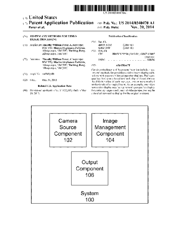
0037 FIG. 1 illustrates a system embodiment of the
present invention;
0038 FIG. 2 illustrates two users and two output compo
nents according to the present invention;
0039 FIG. 3A illustrates another system embodiment of
the present invention;
0040 FIG. 3B illustrates yet another system embodiment
of the present invention;
0041 FIG. 4 illustrates a flowchart representing a method
embodiment of the present invention;
0042 FIG. 5A illustrates a panoramic perspective display
of a video image:
0043 FIG. 5B illustrates a detailed perspective display of
a video image:
0044 FIG. 6A illustrates a frame of a video image cap
tured directly from a camera source component;
004.5 FIG. 6B illustrates the frame of FIG. 6A that has
been minimized;
0046 FIG. 6C illustrates a frame of a video image that has
been interpolated using the nearest neighbor approach:
0047 FIG. 6D illustrates a frame of a video image that has
been interpolated using the bilinear approach;
0048 FIG. 6E illustrates a frame of a video image that has
been interpolated using the bicubic approach:
0049 FIG.6F illustrates a frame of a video image that has
been interpolated using the lanczos4 approach;
0050 FIG. 7 illustrates an exemplary computer system;
0051 FIG. 8 illustrates an exemplary cloud computing
system; and
Nov. 20, 2014
0.052 FIG. 9 illustrates a user interface according to the
present invention.
DETAILED DESCRIPTION
0053 For purposes of this application, the present inven
tion is discussed in reference to systems and methods of video
image processing configured for use during minimally inva
sive Surgeries, but the discussion is merely exemplary. The
present invention is applicable to any function for which a
single camera source component providing two different high
resolution perspective displays of a target is useful.
0054 Minimally invasive surgery may include various
benefits such as reduced post-operative discomfort, reduced
chance of infection, quicker recovery times, shorter hospital
stays, quicker return to full activity, Smaller external scars,
and less internal scarring. Accurate and precise manipulation
of Surgical tools or instruments is desired during any Surgical
procedure, but this is particularly true with minimally inva
sive Surgery.
0055 Laparoscopic surgery is one type of minimally inva
sive Surgery performed through Small incisions. During lap
aroscopic Surgeries, the health care professionals typically
insert a video-capturing laparoscope into the body of the
patient and thread the laparoscope through the body to reach
a site of interest. Visualization of the operative field is pro
vided by the laparoscope and is the “eyes' for the entire
Surgical team. Adapting the view of the operative field to meet
changing conditions is possible by panning the laparoscope.
However, conventional laparoscopes cause only a single per
spective of the operative field to be projected on the video
monitor at a given moment. Although the entire Surgical team
can see the operative field, the visual requirements of the
primary Surgeon differ from a Surgeons assistant, termed an
'assistant for purposes of this application. The primary Sur
geon typically needs to see a lot of detail about the Surgical
site, while the assistant needs to see a wider view of the
Surgical site. More specifically, the assistant may need to
manipulate instruments out of their visual field. A single,
shared perspective therefore may not be optimally informa
tive for the needs of individual surgical team members. Func
tioning without visual feedback is inefficient and potentially
dangerous. Clearly, different perspective displays tailored to
the different roles of the surgical team such as those provided
by the present invention are needed.
0056. As illustrated in FIG. 1, certain embodiments of the
present invention include a camera source component 102, an
image management component 104, and one or more output
components 106.
0057. As illustrated in FIG. 2, the system 100 may include
more than one output component such as a first output com
ponent 106A and a second output component 106B. Each
output component 106 may include a display element 108
configured to show a perspective display of a video image or
other portion of a video image. FIG. 2 illustrates an embodi
ment in which a video image is converted into a first perspec
tive display 110A configured as a detailed perspective display
and a second perspective display 110B configured as a pan
oramic perspective display. Each perspective display 110 is
tailored for the anticipated needs of the intended user 50, in
certain embodiments, a surgeon 50A or an assistant 50B.
0.058 As illustrated in FIG.3, an image management com
ponent 104 may include a video image receiving element 112,
an interpolation element 114, a frame rate control element
�Nov. 20, 2014
US 2014/0340470 A1
116, a first temporary storage element 118A, and a second
temporary storage element 118B.
0059. As illustrated in FIG.4, certain embodiments of the
present invention include method 200 steps configured to be
implemented by the system. For example, in certain embodi
ments, the camera source component captures a video image
of a target 202 and sends the video image to the video image
receiving component. Two or more portions of the video
image—that is, the detailed precursor frames and the pan
oramic precursor frames—may be treated to different steps
throughout the process.
0060. The system crops the detailed precursor frames to
remove certain non-site segments—typically peripheral seg
ments—of the video image that do not display the specific site
of interest 204. Because the non-site segments of the video
image has been removed, the remaining site section of the
Video image can be enlarged to fill the space formerly occu
pied by the non-site segments. (An example of a non-cropped
image frame is illustrated in FIG. 5A and a cropped image
frame is illustrated in FIG. 5B.)
0061. However, when enlarging the video image, some
resolution or other quality characteristic may have been
reduced. Accordingly, in certain embodiments, the detailed
precursor frames are interpolated 208. A number of interpo
lation methods are available and, in certain embodiments,
which interpolation method is applied may be automatically
chosen by the system.
0062 More specifically, examples of interpolation meth
ods include anisotropic approaches, regularized local linear
ized regression model for edge preserved interpolation
approach, nearest-neighbor approach, bilinear approach,
bicubic approach, and Lanczos4 approach.
0063. The anisotropic approaches and regularized local
linearized regression model approaches for edge preserved
interpolation approach may be used in certain embodiments;
however, they may not be chosen in others because of pos
sible incompatibility with arbitrary Zooming function of cer
tain embodiments of the system.
0064. In nearest neighbor interpolation, the interpolated
pixel takes the value of its nearest neighbor. In terms of
memory accesses, the image is analyzed row-by-row. In an
efficient implementation, a single image row is stored in a
cache. The nearest-neighbor interpolation method requires
the minimum number of memory accesses while not requir
ing the implementation of any arithmetic operations. An
example of a nearest neighbor interpolated image is illus
trated in FIG. 6C. To contrast, an uninterpolated image is
illustrated in FIG. 6A and a minimized image is illustrated in
FIG. 6B.
0065 However, because introduction of significant block
artifacts at significant Zooming levels, this approach is most
effective for lower-level Zooming.
006.6 Bilinear interpolation includes the determination of
the 4 nearest points. This is implemented in two phases. First,
the sections along the columns are interpolated. Second, the
sections along the rows are interpolated. The implementation
is based on:
f(x+p, y)= f(x, y) (1-p)-f(x+1, y)p,
f(x+p, y--q) f(x+p, y) (1-q)-f(x+p, y-1)"q,
(1)
(2)
0067 where p, q 6 (0, 1). Compared to nearest-neighbor
interpolation, bilinear interpolation does not suffer from
severe blocking artifacts. Bilinear interpolation provides a
balance between computational efficiency and interpolation
accuracy. An example of a bilinear interpolated image is
illustrated in FIG. 6D.
0068. In Bicubic interpolation, the nearest neighbor points
(4x4 neighborhood) are used to estimate the interpolated
pixel. The approach is separable in the sense that we interpo
late along the rows and columns separately. It is an extension
of bilinear interpolation in the sense that it fits the data with a
piecewise cubic model. Naturally, this higher-order model
comes with need for more continuity in the image. An
example of a bicubic interpolated image is illustrated in FIG.
6E.
0069. The Lanczos interpolation approach is based on the
sinc function. Here, the sinc function may be the optimal
choice for band-limited signals. However, unlike real images,
band-limited signals are infinite. Also, the sinc function itself
is infinite. Furthermore, if the edges are modeled using step
functions, band-limited approximations may produce ringing
artifacts around each edge. Lanczos interpolation is thus
based on truncating the sinc-function over a local, 8x8 win
dow of the nearest neighboring pixels. An example of a Lan
sczos4 interpolated image is illustrated in FIG. 6F.
0070 Table 1 illustrates the computational efficiency of
certain of the approaches in a per pixel format.
Nearest
Additions. Subtractions
Multiplies
0071
neighbor
Bilinear
Bicubic
Lanczos4
O
O
3
2
17
22
15
40
Additional embodiments are described below.
0072. In certain embodiments, the video images may be
captured at 1920x1088 pixels per frame at 30 fps, while in
other embodiments video images may be captured at 720x
480 pixels per frame at 30 fps.
0073. The system balances the frame rate of the detailed
precursor frames—those that have been cropped, enlarged,
and interpolated—and the panoramic precursor frames to
concurrently maximize the video image quality for both dis
plays 210. The frame rate for the detailed precursor frames
may be maintained at a relatively higher rate to allow for
detection of rapidly-changing events or status of the target,
and the frame rate for the panoramic precursor frames—may
be decreased to conserve certain computational resources that
are then allocated to generating the detailed perspective dis
play. For example, in certain embodiments, the system may
automatically select (or permit a user to select) a temporal
frame reduction factor configured to set the frame rate for the
non-altered frames. A temporal frame reduction factor of 1 is
equal to the original frame rate, while a frame rate of 6
includes flashing 1 out of every 6 frames relative to the origi
nal frame rate. By reducing the update rate of the panoramic
view, higher quality detailed perspective displays may be
produced.
0074. In certain embodiments, the frame rates may be
from 16 to 40 frames per second for the detailed perspective
display. These frame rates can be downsampled, for example,
from 1 to 6 for generating the panoramic perspective display.
(0075 Table 2 (below) illustrates execution times for dif
ferent components of certain embodiments of the present
invention.
�Nov. 20, 2014
US 2014/0340470 A1
(0079 Table 6 (below) illustrates subjective evaluation of
image quality for spatial Zooming for panoramic views for all
Video images, where 5 is best, and 1 is worst.
Time (ms)
Procedure
mean E Std. dev.
Video capture
Video crop
Nearest neighbor interp.
Bilinear interp.
Bicubic interp.
Lanczos4 interp.
Video display
O427
O.OSO 1.53
8.38
12.25 24.17
10.38
OO13
O
O.O74
O.304
O.S39
O.487
0.047
Int. Meth.
Down. Fr. Rate
1
0076 Table 3 (below) illustrates frame rates (in frames per
second) for the altered frames configured to form a detailed
perspective display in certain embodiments.
Int. Method
Nearest
Down. Fr. rate
neighbor
Bilinear
Bicubic
Lanczos4
1
2
3
4
5
6
24.87
31.88
34.41
36.62
37.98
39.11
22.05
27.90
30.66
31.82
33.53
34.72
21.08
26.26
28.41
29.55
30.65
31.32
16.93
1994
21.08
21.72
22.28
22.91
0077 Table 4 (below) illustrates the mean reconstructed
PSNR/SSIM over 100 interpolated video frames in certain
embodiments. PSNR is in dB and SSIM is bounded above by
1.
Int. Method
Neares
Sp. Down. rate neighbor
2x2
3x3
4x4
SXS
6x6
7x7
8x8
25.24 dB,
O.7343
23.77 Bf
0.6627
22.70 Bf
0.615S
22.78 dB;
O.6289
22.34 dB
0.6133
21.87 Bf
O.S974
21.19 dB
O.S714
Bilinear
Bicubic
Lanczos4
28.75 dB,
O.8485
26.70 dB.
O.7844
24.88 dB,
O.71.99
24.29 dB.
O.7019
24.28 dB,
O.7O60
23.54 dB.
O.6805
23.03 dB.
O.6672
28.45 dB,
O.8455
26.23 dB.
0.7789
24.32 dB
O.71OO
23.77 Bf
O.6959
23.72 B,
O.7OO6
22.97 Bf
O.6741
22.42 dB
O.6588
28.34 dB,
O.8392
26.05 dB,
0.7677
24.14 dB,
O.6974
23.59 dB
O.6824
23.5.1 dB.
O.6858
22.77 B.
O.6608
22.24 dB,
O.6461
0078 Table 5 (below) illustrates a subjective user evalua
tion of image quality for spatial Zooming in detailed perspec
tive display for all video images, where the score of 5 is best,
and the score of 1 is worst. The unaltered video image scored
an average score of 4.
Int. Method
Nearest
Sp. Down. rate
neighbor
Bilinear
Bicubic
Lanczos4
2x2
3x3
4x4
3
1875
1.75
3.25
2.625
2
3.25
2.5
2
3.12S
2.375
2
2
4
Nearest
neighbor
Bilinear
Bicubic
Lanczos4
3.5.
3.75
4.125.3
3.875.4
4.125,
4.125
4.125,
2.375
4.125,
1.75
3.5
3.375
3.625,
2.75
4.125.
1.75
4.S.
2.375
3.625,
3.25
4.2
0080 Back to the method steps, the detailed precursor
frames may be stored in a first temporary storage component
and the panoramic precursor frames may be stored in a second
temporary storage component.
I0081. Subsequently, the detailed precursor frames result
ing in the detailed perspective display may be shown in a first
output component 212. The panoramic precursor frames
resulting in the panoramic perspective display may be shown
in a second output component 214.
I0082 In certain embodiments, the system may be config
ured to detect certain features of the target (e.g., body tissue,
body organ, Surgical instrument) and the image display may
be changed to highlight that feature.
I0083 FIG. 7 illustrates an exemplary computer system
300 that may be used to implement the methods according to
the invention. One or more computer systems 300 may carry
out the methods presented hereinas computer code. In certain
embodiments, the computer system 300 is configured to
define the settings of the camera source component, one or
more elements of the image management component, and/or
the output component.
I0084 Computer system 300 includes an input/output
interface 302 connected to communication infrastructure
304—such as a bus—, which forwards data such as graphics,
text, and information, from the communication infrastructure
304 or from a frame buffer (not shown) to other components
of the computer system 300. The input/output interface 302
may be, for example, a keyboard, touch screen, joystick,
wand, video game controller, trackball, mouse, monitor,
speaker, printer, Google Glass(R unit, webcamera, any other
computer peripheral device, or any combination thereof,
capable of entering and/or viewing data.
I0085 Computer system 300 includes one or more proces
sors 306, which may be a special purpose or a general-pur
pose digital signal processor that processes certain informa
tion. Computer system 300 also includes a main memory 308,
for example random access memory (“RAM), read-only
memory (“ROM), mass storage device, or any combination
thereof. Computer system 300 may also include a secondary
memory 310 such as a hard disk unit 312, a removable storage
unit 314, or any combination thereof. Computer system 300
may also include a communication interface 316, for
example, a modem, a network interface (such as an Ethernet
card or Ethernet cable), a communication port, a PCMCIA
slot and card, wired or wireless systems (such as Wi-Fi,
Bluetooth, Infrared), local area networks, wide area net
works, intranets, etc.
I0086. It is contemplated that the main memory 308, sec
ondary memory 310, communication interface 316, or a com
�Nov. 20, 2014
US 2014/0340470 A1
bination thereof, function as a computer usable storage
medium, otherwise referred to as a computer readable storage
medium, to store and/or access computer Software including
computer instructions. Certain embodiments of a computer
readable storage medium do not include any transitory sig
nals or waves. For example, computer programs or other
instructions may be loaded into the computer system 300
Such as through a removable storage device, for example, a
floppy disk, ZIP disks, magnetic tape, portable flash drive,
optical disk such as a CD or DVD or Blu-ray. Specifically,
computer software including computer instructions may be
transferred from the removable storage unit 314 or hard disc
unit 312 to the secondary memory 310 or through the com
munication infrastructure 304 to the main memory 308 of the
computer system 300.
0087 Communication interface 316 allows software,
instructions and data to be transferred between the computer
system 300 and external devices or external networks. Soft
ware, instructions, and/or data transferred by the communi
cation interface 316 are typically in the form of signals that
may be electronic, electromagnetic, optical or other signals
capable of being sent and received by the communication
interface 316. Signals may be sent and received using wire or
cable, fiber optics, a phone line, a cellular phone link, a Radio
Frequency (“RF) link, wireless link, or other communica
tion channels.
0088 Computer programs, when executed, enable the
computer system 300, particularly the processor 306, to
implement the methods of the invention according to com
puter software including instructions.
I0089. The computer system 300 described herein may
performany one of, or any combination of the steps of any of
the methods presented herein. It is also contemplated that the
methods according to the invention may be performed auto
matically, or may be invoked by some form of manual inter
vention.
0090. The computer system 300 of FIG. 7 is provided only
for purposes of illustration, such that the invention is not
limited to this specific embodiment. It is appreciated that a
person skilled in the relevant art knows how to program and
implement the invention using any computer system.
0091. The computer system 300 may be a handheld device
and include any Small-sized computer device including, for
example, a personal digital assistant ("PDA), Smart hand
held computing device, cellular telephone, or a laptop or
netbook computer, hand held console or MP3 player, tablet,
or similar hand held computer device, such as an iPadR, iPad
Touch(R) or iPhone(R).
0092 FIG. 8 illustrates an exemplary cloud computing
system 400 that may be used to implement the methods
according to the present invention. The cloud computing sys
tem 400 includes a plurality of interconnected computing
environments. The cloud computing system 400 utilizes the
resources from various networks as a collective virtual com
puter, where the services and applications can run indepen
dently from a particular computer or server configuration
making hardware less important.
0093 Specifically, the cloud computing system 400
includes at least one client computer 402.The client computer
402 may be any device through the use of which a distributed
computing environment may be accessed to perform the
methods disclosed herein, for example, a traditional com
puter, portable computer, mobile phone, personal digital
assistant, tablet to name a few. The client computer 402
includes memory such as random access memory (RAM),
read-only memory (“ROM), mass storage device, or any
combination thereof. The memory functions as a computer
usable storage medium, otherwise referred to as a computer
readable storage medium, to store and/or access computer
Software and/or instructions.
0094. The client computer 402 also includes a communi
cations interface, for example, a modem, a network interface
(such as an Ethernet card), a communications port, a PCM
CIA slot and card, wired or wireless systems, etc. The com
munications interface allows communication through trans
ferred signals between the client computer 402 and external
devices including networks such as the Internet 404 and cloud
data center 406. Communication may be implemented using
wireless or wired capability such as cable, fiber optics, a
phone line, a cellular phone link, radio waves or other com
munication channels.
0.095 The client computer 402 establishes communica
tion with the Internet 404—specifically to one or more serv
ers—to, in turn, establish communication with one or more
cloud data centers 406. A cloud data center 406 includes one
or more networks 410a, 410b, 410c managed through a cloud
management system 408. Each network 410a, 410b, 410c
includes resource servers 412a, 412b, 412c, respectively.
Servers 412a, 412b, 412c permit access to a collection of
computing resources and components that can be invoked to
instantiate a virtual machine, process, or other resource for a
limited or defined duration. For example, one group of
resource servers can host and serve an operating System or
components thereof to deliver and instantiate a virtual
machine. Another group of resource servers can accept
requests to host computing cycles or processortime, to Supply
a defined level of processing power for a virtual machine. A
further group of resource servers can host and serve applica
tions to load on an instantiation of a virtual machine, such as
an email client, a browser application, a messaging applica
tion, or other applications or software.
0096. The cloud management system 408 can comprise a
dedicated or centralized server and/or other software, hard
ware, and network tools to communicate with one or more
networks 410a, 410b, 410c, such as the Internet or other
public or private network, with all sets of resource servers
412a, 412b, 412c. The cloud management system 408 may be
configured to query and identify the computing resources and
components managed by the set of resource servers 412a,
412b, 412c needed and available for use in the cloud data
center 406. Specifically, the cloud management system 408
may be configured to identify the hardware resources and
components such as type and amount of processing power,
type and amount of memory, type and amount of storage, type
and amount of network bandwidth and the like, of the set of
resource servers 412a, 412b, 412c needed and available for
use in the cloud data center 406. Likewise, the cloud manage
ment system 408 can be configured to identify the software
resources and components, such as type of Operating System
(“OS), application programs, and the like, of the set of
resource servers 412a, 412b, 412c needed and available for
use in the cloud data center 406.
0097. The present invention is also directed to computer
products, otherwise referred to as computer program prod
ucts, to provide software to the cloud computing system 400.
Computer products store software on any computer usable
medium, known now or in the future. Such software, when
executed, may implement the methods according to certain
�Nov. 20, 2014
US 2014/0340470 A1
embodiments of the invention. Examples of computer usable
mediums include, but are not limited to, primary storage
devices (e.g., any type of random access memory), secondary
storage devices (e.g., hard drives, floppy disks, CD ROMS,
ZIP disks, tapes, magnetic storage devices, optical storage
devices, Micro-Electro-Mechanical Systems (“MEMS),
nanotechnological storage device, etc.), and communication
mediums (e.g., wired and wireless communications net
works, local area networks, wide area networks, intranets,
etc.). It is to be appreciated that the embodiments described
herein may be implemented using software, hardware, firm
ware, or combinations thereof.
0098. The cloud computing system 400 of FIG. 8 is pro
vided only for purposes of illustration and does not limit the
invention to this specific embodiment. It is appreciated that a
person skilled in the relevant art knows how to program and
implement the invention using any computer system or net
work architecture.
0099 FIG. 9 illustrates a user interface 500 according to
certain embodiments of the present invention. A user inter
face 500 may include a number of fields 502 configured to
permit a user to enter information (e.g., settings for some
element or component of the system). For example, fields 502
may include a capture resolution field 502A, preview resolu
tion field 502B, interpolation method field 502C, or a pan
oramic downsample field 502D. The user interface 502 also
may include navigation buttons 504 and illustrate information
already set or gathered in a context information field 506.
0100 While the disclosure is susceptible to various modi
fications and alternative forms, specific exemplary embodi
ments of the present invention have been shown by way of
example in the drawings and have been described in detail. It
should be understood, however, that there is no intent to limit
the disclosure to the particular embodiments disclosed, but on
the contrary, the intention is to cover all modifications,
equivalents, and alternatives falling within the scope of the
disclosure as defined by the appended claims.
1. A system for producing a panoramic perspective display
and a detailed perspective display from a single video image
Source, comprising:
capturing an input video image into a first frame memory to
obtain a first image;
cropping a selected area of the first image from the first
frame memory to obtain a cropped image;
conducting interpolation to map the cropped image into a
second frame memory;
copying to a display buffer the first image from the first
frame memory and the cropped image from the second
frame memory;
displaying from the display buffer the first image on a first
user interface and the cropped image on a second user
interface; and
reconfiguring in real-time at least one of the first image and
cropped image to meet changing Surgical needs during a
Surgical operation.
2. A system for providing a two or more perspective dis
plays of a single video image, comprising:
a processor;
a main memory in communication with the processor via a
communication infrastructure and storing instructions
that, when executed by the processor, cause the proces
SOr to:
capture a video image of a target, wherein the video
image is comprised of one or more video image
frames and a first portion of the video frames form
detailed precursor frames and a second portion of the
Video frames form panoramic precursor frames;
crop detailed precursor frames to remove non-site seg
ments that do not display a narrow site of interest;
interpolate the detailed precursor frames:
balance frame rate of detailed precursor frames relative
to panoramic precursor frames to improve efficiency
by reducing computational resources used for the
panoramic precursor frames so as to provide more
computational resources for generating the detailed
precursor frames;
show the detailed precursor frames resulting in a
detailed perspective display via a first output compo
nent; and
show the panoramic precursor frames resulting in a pan
oramic perspective display via a second output com
ponent.
3. The system of claim 2, wherein the interpolate step
includes computing pixel values from lower resolutions to
increase perceived quality of the output video image.
4. The system of claim 2, wherein the interpolate step is
conducted using a nearest-neighbor approach.
5. The system of claim 2, wherein the interpolate step is
conducted using abilinear approach.
6. The system of claim 2, wherein the interpolate step is
conducted using a bicubic approach.
7. The system of claim 2, wherein the interpolate step is
conducted using a Lanczos4 approach.
8. The system of claim 2, wherein the main memory in
communication with the processor via a communication
infrastructure and storing instructions that, when executed by
the processor, cause the processor also to send the video
image from a camera source component used to capture the
Video image to an image management component.
9. The system of claim 2, wherein the main memory in
communication with the processor via a communication
infrastructure and storing instructions that, when executed by
the processor, cause the processor also to:
store the detailed precursor frames in a first temporary
storage element; and
store the panoramic precursor frames in a second tempo
rary storage element.
10. The system of claim 2, wherein the main memory in
communication with the processor via a communication
infrastructure and storing instructions that, when executed by
the processor, cause the processor also to track the target and
modify a characteristic of the video image based on tracking
of the target.
11. The system of claim 10, wherein the characteristic
modified is a field of view of a camera Source component used
to capture the video image, and the modification is configured
to capture a different set of information about the target.
12. The system of claim 2, wherein the balance step
includes decreasing the display frame rate for the panoramic
precursor frames and maintaining the display rate for the
detailed precursor frames at a frame rate at which the frames
were captured.
13. The system of claim 2, wherein the balance step
includes decreasing the display frame rate for the panoramic
precursor frames by a first temporal frame reduction factor
and decreasing the display rate for the detailed precursor
frames by a second temporal frame reduction factor, wherein
�Nov. 20, 2014
US 2014/0340470 A1
the first temporal frame reduction factor has a higher value
than the second temporal frame reduction factor.
14. The system of claim 2, wherein the first output compo
nent is a monitor and the second output component is a
monitor.
15. The system of claim 2, wherein the first output compo
nent and the second output components are positioned Such
that a user can perceive spatial frequencies that can be
refreshed at frame rates that exceed 30 fps at high contrast.
16. A system for generating two or more perspective dis
plays from a single video image source, comprising:
a camera source component configured to capture a video
image of a target;
an image management component configured to transform
the video image into a set of detailed precursor frames
configured to result in a detailed perspective display and
a set of panoramic precursor frames configured to result
in a panoramic perspective display; and
an output component configured to show a detailed per
spective display and a panoramic perspective display of
a target.
17. The system of claim 16, further comprising a second
output component configured to show a detailed perspective
display or a panoramic perspective display.
18. The system of claim 16, wherein the image manage
ment component includes a video image receiving element,
an interpolation element, a frame rate control element, a first
temporary storage element, and a second temporary storage
element.
19. The system of claim 18, wherein the video image
receiving element is a video capture card.
20. The system of claim 19, wherein the first temporary
storage element is a first framebuffer and the second tempo
rary storage element is a second framebuffer.
k
k
k
k
k
�
 Marios Pattichis