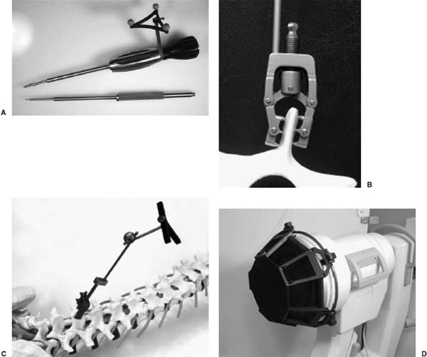
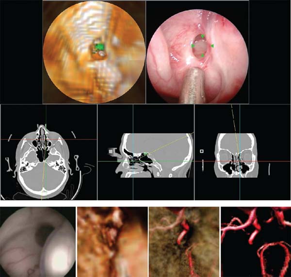
Electronic videoendoscopy is commonly performed for a wide variety of diagnostic and therapeutic procedures due to the advent of miniature charge-coupled device (CCD) cameras and associated microelectronics. An endoscope is basically a long tube through which an image of the surgical space inside the body is transmitted to the surgeon. This tube may be rigid for areas easily accessible through an incision, or flexible to extend through twisting paths, as in pulmonary airways or the gastrointestinal tract. In current systems, the image is presented on a video monitor. The image is passed through the tube, either by lens optics in a rigid endoscope or by fiberoptics in a flexible endoscope, to a CCD video camera at the surgeon’s end.1 Improvements in CCD technology have alternatively made it possible to locate the CCD array at the endoscope tip. A light source is transmitted to the endoscope tip through fiberoptics in all endoscopes. This technology is packed into a tube ranging from a few millimeters to a centimeter in diameter. For some operations, typically those that require flexible endoscopes, instruments are passed through a working channel in the endoscope. In operations where the surgical space is more easily accessible, a rigid endoscope and multiple instruments are inserted through separate incisions. Open spine surgery requires extensive soft tissue dissection. Muscle retraction during surgery has been shown to cause short-term damage and long-term, degenerative changes.2–5 Most of the recovery involved in open spinal procedures is due to the soft tissue dissection and muscle trauma.6 This trauma necessitates long recovery time and extended loss of work.7,8 Recovery from open spinal surgery exposes the patient to prolonged opiate analgesia. Pain management researchers agree that such analgesia poses a nontrivial risk of initiating, or exacerbating, addiction in the recovering patient.9,10 In minimally invasive surgical procedures, endoscopes are inserted through natural orifices of the body or small (typically 5–10 mm) incisions. The endoscope illuminates the surgical region of interest and transmits camera images to a video monitor. Such minimally invasive procedures as endoscopic/percutaneous laminotomy, diskectomy, pedicle screw fixation, and vertebroplasty can reduce morbidity relative to traditional open procedures. Surgery performed through small incisions is often much less traumatic than the same surgery done through large incisions. Minimally invasive procedures have proven to be effective, reduce postoperative pain, shorten the hospital stay, help the patient resume normal activity, and reduce the surgical complication rate.11–19 These advantages unfortunately do not come without costs. What is better for the patient is often awkward for the surgeon, who has typically relied heavily on dexterity, tactile feedback, and excellent hand-eye coordination, and who now must operate while looking at a video monitor displaying endoscopic images. Dexterity limitations20 and tactile limitations21 are obvious and well known. There are also several fundamental vision problems. The surgeon’s natural hand-eye coordination is severely degraded, and there are difficulties with depth perception and spatial orientation.22 These visualization problems (compared with open surgery) are due to a variety of factors, including monocular vision (although stereoscopic systems are possible), a limited field of view, peripheral image distortions, and the projection of a natural three-dimensional (3D) surgical scene on a two-dimensional (2D) display. Also, endoscopes can display only visible surfaces, and it is therefore generally difficult to visualize tumors, nerves, vessels, and other anatomic structures that lie beneath opaque tissue. Image-guided surgery (IGS) systems are widely used in a variety of cranial and open spinal procedures.23–26 Such systems have the promise of addressing some of the visualization problems inherent with endoscopic and minimally invasive spine surgery. This chapter will describe currently available fluoroscopy-based and CT- based IGS systems, review some of the key issues and challenges for the application of these systems to image-guided endoscopic and minimally invasive spine surgery, discuss the relevance of IGS for pedicle screw placement, and describe a promising new approach called image-enhanced endoscopy. Fluoroscopy-Based Image-Guided Surgery Fluoroscopy is an imaging method that is useful and familiar to musculoskeletal surgeons. It is routinely employed for intraoperative visualization of patient anatomy, particularly bony anatomy, and surgical instrument position. Such radiographic visualization facilitates reduced surgical exposure and improved accuracy for a wide variety of spine procedures. Despite its widespread acceptance and utility, fluoroscopy has limitations and disadvantages. Perhaps the most important disadvantage is occupational radiation exposure, particularly to the surgeon’s hands.27–29 Data have suggested that spinal surgeons, in particular, are at significant risk for fluoroscopy-related radiation exposure.30 Another limitation associated with conventional use of a C-arm fluoroscope is that only one x-ray projection image can be acquired and visualized at a time (without using a second fluoroscope). Thus, for procedures that require the use of images obtained from multiple orientations, it is necessary to reposition the C-arm repeatedly throughout the procedure. Frequent repositioning of a C-arm fluoroscope in a crowded operative field is often ergonomically challenging. Furthermore, it is generally difficult to position and orient a surgical probe or instrument properly when it can be seen in only one projection image at a time. Fluoroscopy-based IGS systems have been developed to overcome these limitations and disadvantages. Such systems track surgical probes and instruments and display their positions in real time on one or more previously acquired fluoroscopic images. Some authors refer to this process as virtual fluoroscopy 31–33 (see note “a”). The fundamental ideas of fluoroscopy-based IGS were first presented by Potamianos et al34,35 and subsequently developed by other investigators.31,36–40 The original work used a robotic manipulator. Most current systems use an optical tracking system.31 Several systems are available (e.g., the FluoroNav Virtual Fluoroscopy System, which is integrated in the StealthStation Treatment Guidance System, Medtronic, Surgical Navigation System, Louisville, CO). The main components of a typical fluoroscopy-based IGS system are a computer workstation and monitor, a tracking system, a conventional C-arm fluoroscope, a calibration device that attaches to the imaging head of the fluoroscope, a spine clamp with a dynamic reference frame (DRF), and a variety of optically tracked instruments (Fig. 34–1). The calibration device basically consists of two parallel plates that contain radiopaque metal spheres. Although various kinds of tracking systems can be used, including electromagnetic, magnetic, and ultrasonic, most current systems use an optical tracking system. Such a system generally consists of two or more optical sensors or cameras that detect infrared light emitting diodes (IREDs) or photoreflective spheres or disks that are mounted on the calibration device, the DRF attached to the spine clamp, and the surgical instruments. Using mathematical principles of localization by triangulation, the system determines the spatial position and orientation of the instruments (and DRF and calibration device) to provide real-time navigation. Multiple instruments can be tracked simultaneously during a procedure. In the case of actively tracked instruments using IREDs, each instrument IRED array is strobed individually by the tracking system. In the case of passively tracked instruments using photoreflective spheres or disks, the tracking system can identify different instruments if they have distinct marker configurations. At the beginning of surgery, the fluoroscope is positioned in the usual fashion, the calibration device is attached to the imaging head (image intensifier), and the fluoroscope is sterilely draped. The DRF is attached to the spinous process of the spine segment of interest, or an adjacent segment, with a clamp or a modified screw.41,42 The DRF allows patient movement to be tracked. One or more fluoroscopic images are obtained with the vertebral segments of interest centered in the field of view to minimize the effects of parallax. Each fluoroscopic image is transferred at the time of acquisition from the fluoroscope to the computer workstation through a standard video cable (or a digital link). The optical tracking system simultaneously determines the position of the calibration device and the DRF and thereby determines the position of the C-arm relative to the patient at the time of image acquisition. The computer digitizes the acquired fluoroscopic image and calibrates the image using the positions of the radiopaque calibration markers that appear in the fluoroscopic image (Fig. 34–2) and the position of the C-arm relative to the patient. During the calibration process, the computer constructs a mathematical model of the fluoroscopic image formation process, which describes where a given position relative to the patient projects onto the fluoroscopic image. The mathematical model can be different for every acquired image for a variety of reasons (e.g., mechanical deformation of the C-arm, geometric distortion in the image intensifier image due to a change in position of the image intensifier relative to the earth’s magnetic field and electromagnetic fields near the C-arm generated by electrical devices in the operating room). Because of this, the calibration device is left on the imaging head, and calibration is performed independently for every acquired fluoroscopic image. After the fluoroscopic images are acquired and calibrated, the optical tracking system determines the positions of instruments and the DRF and uses the relative instrument positions plus the image formation model to overlay in real-time graphic representations of the tracked instruments on all preacquired fluoroscopic images (Fig. 34–2). The graphic overlays appear where the instruments would appear if new fluoroscopic images were acquired. Additional information can also be displayed, such as the trajectory (linear extension) of the instrument. FIGURE 34–1 Some image-guided spine surgery system components. (A) An awl with an array of photoreflective spheres. Other surgical tools that can be tracked and used with an image-guided surgery (IGS) system include a bone tap, pedicle probe, drill guide, drill, and screwdriver. (B) A spine clamp attached to a spinous process. (C) A spine clamp with a dynamic reference frame (DRF) of infrared light emitting diodes (IREDs). (D) A calibration device attached to the imaging head of a C-arm fluoroscope. The calibration device basically consists of two parallel plates containing radiopaque metal spheres and has many IREDs mounted around its circumference. Fluoroscopy-based IGS has several distinct advantages over conventional C-arm fluoroscopy.31 First, radiation exposure to the patient and the surgical team is substantially reduced. Surgical probes and instruments are tracked and their positions overlaid on previously acquired fluoroscopic images. Thus, unlike conventional fluoroscopy, it is not necessary to acquire a temporal sequence of images to follow a probe or instrument. Because the fluoroscopic images used for surgical navigation are acquired once, or at most a few times, during the procedure, the surgical team can stand at a safe distance during image acquisition, thereby minimizing if not eliminating the need to wear heavy lead shielding. Second, the surgeon can acquire several images from different orientations and use all or some of them simultaneously for multiplanar navigation; the positions of tracked surgical probes and instruments are overlaid in real time on all preacquired fluoroscopic images. This eliminates the need to reposition the C-arm repeatedly, as is necessary during conventional fluoroscopy. Third, the C-arm fluoroscope may be removed from the operative field after image acquisition, which improves the ergonomics in a crowded surgical environment. Fourth, a fluoroscopy-based IGS system can enhance conventional fluoroscopy images by providing additional quantitative information to the surgeon. For example, the trajectory of the instrument can be displayed (e.g., the instrument can be displayed in one color and its linear extension in another color), and such measurements as distances (e.g., pedicle screw length or probe tip distance from midline) and angles (e.g., instrument trajectory angle relative to the midsagittal plane) can be obtained. Finally, there are several advantages relative to conventional IGS systems that use preoperative computed tomography (CT) or magnetic resonance imaging (MRI). No specially acquired preoperative image is required, which eliminates the associated time, cost, and logistical difficulties. Also, the challenging and time-consuming task of preoperative image-to-physical registration is not necessary. Because fluoroscopy is an intraoperative imaging technique, intraoperative image, updating is achieved simply by acquiring a new fluoroscopic image; for example, after patient movement or a change in intersegmental relationships caused by a surgical intervention (distraction of an interspace, reduction of a deformity). Validation of the virtual instrument overlays is achieved simply by acquiring a fluoroscopic image and visually comparing the position of the instrument in the image with the virtual overlay. FIGURE 34–2 Fluoroscopy-based surgical navigation. In a fluoroscopy-based image-guided surgery (IGS) system, surgical probes and instruments are tracked and their changing positions overlaid in real time on previously acquired fluoroscopic images. The surgeon can acquire several images from different orientations and use all or some of them simultaneously for multiplanar navigation. This eliminates the need to reposition the C-arm repeatedly, as is necessary during conventional fluoroscopy. In this example, a probe (green) and its linear extension (yellow dotted line) are displayed on anteroposterior (right panel) and lateral (two left panels) fluoroscopic images. The original position of the probe can be seen as a dark structure in the previously acquired images. The black dots in the fluoroscopic images are radiopaque markers contained in the calibration device that attaches to the C-arm and are used for image calibration. The most important limitation of fluoroscopy-based IGS is that navigation is based on 2D x-ray projection images rather than 3D CT images. The 3D anatomy must be inferred from the 2D projection information. The clinical interpretation of 2D images is highly dependent on the skill and experience of the surgeon. The other main limitation is the nature of fluoroscopic images. For example, it is often difficult to obtain clinically adequate fluoroscopic images in an obese patient. Such radiopaque surgical tools as retractors obscure patient anatomy. It is important to use good fluoroscopic technique. In particular, the surgical region of interest should be centered in the fluoroscopic image field of view to minimize the effects of parallax. CT-Based Image-Guided Surgery Spinal IGS applications are a relatively recent addition to neurosurgery and were adapted from well-established cranial IGS technology.23–26 The purpose of applying stereotactic principles to spine surgery is to improve the surgeon’s orientation to the unexposed anatomy. The 3D anatomy of the spinal column can present difficulties for even the most experienced surgeon. This is especially true for percutaneous and endoscopic approaches. The ability to conceptualize the 3D anatomy of the spinal column from any particular approach varies among surgeons. It is highly dependent on the correct interpretation of both preoperative and intraoperative images. As mentioned previously, the most important limitation of fluoroscopy-based IGS is that navigation is based on 2D x-ray projection images. This can provide only a 2D projection view of complex 3D anatomy. The surgeon must estimate the position of unexposed spinal structures based on an interpretation of these 2D projection images and a knowledge of pertinent anatomy. Such inference can result in varying degrees of inaccuracy (e.g., when placing screws in the spinal column). A CT-based IGS system facilitates this image interpretation process by providing a variety of 2D reformatted image slices and 3D renderings and displaying in real time the position and orientation of tracked instruments on these images. The primary advantage of CT-based IGS is that navigation is based on 3D preoperative CT images, which fundamentally allows a CT-based system to reveal better 3D anatomical information to the surgeon than a fluoroscopy-based system. The general steps required to perform CT-based IGS for spinal procedures are relatively similar for all systems. Prior to surgery, a CT image of the appropriate spinal segments is obtained using a specific protocol. The CT image consists of a 3D volume of contiguous axial CT image slices. The scan protocol is often recommended by the IGS vendor to ensure correct image parameters. The spatial resolution of the image is limited by the voxel dimensions: spatial sampling (discretization) of the underlying continuous image constitutes loss of information by partial volume averaging, so structural information on the scale of the voxel dimension and smaller is lost. Thus, it is helpful to acquire images for IGS that have small voxel dimensions. We believe that CT images for IGS should be acquired with ~1 mm slice thickness or smaller. Once the patient has been scanned, the image is transferred to the IGS computer workstation (e.g., via a network or optical media). Preoperative planning is performed at the IGS computer workstation at the surgeon’s convenience. The software is used to reconstruct the images. A wide variety of 2D reformatted image slices and 3D renderings based on the preoperative CT image are possible (Fig. 34–3). The 2D reformatted image slices can be standard triplanar (i.e., axial, sagittal, and coronal) views as well as views parallel and orthogonal to a planned trajectory or axis of a planned pedicle screw. The 3D rendering can be rotated, and in some systems the color and transparency of various tissues and segmented volumes of interest can be interactively adjusted. The combination of zoom, pan, slice scrolling, a distance measurement tool, multiple 2D reformatted image slices, and a rotatable 3D rendering allows the surgeon to understand the anatomical relationships, which is especially important in the presence of diseased and distorted anatomy. For pedicle screw placement, the position (entry point), trajectory, and screw dimensions (length and width) can be interactively manipulated and evaluated to obtain an appropriate fit. The plan can be stored and used intraoperatively to select the appropriate screw, to find the entry point, and to follow the selected trajectory. Most systems provide some type of targeting view during placement, which is generally more useful than other views during actual placement and minimizes the number of images displayed on the computer screen. Some authors report that for pedicle screw placement, the ability of the planning software to help the surgeon understand complex anatomical relationships and determine an appropriate pedicle screw entry point, trajectory, and dimensions improves surgical planning and is of equal or greater importance than the use of the IGS system for intraoperative navigation.43–45 The main components of a CT-based IGS system are basically the same as those of a fluoroscopy-based IGS system, except that there is not a C-arm fluoroscope or calibration device that attaches to the fluoroscope: a computer workstation and monitor, a tracking system, a spine clamp with a DRF, and a variety of optically tracked instruments. The patient is positioned on the operating room table as for a conventional spinal procedure. The computer monitor is placed so that the surgeon has a clear view. Some systems have a lightweight, flat-panel monitor mounted on a boom that can be positioned over the operative field. These displays, which are covered by a clear, sterile drape during surgery, sometimes have a touch-sensitive screen so that the surgeon can easily interact with the software during the procedure. The optical position sensor (camera array) is placed such that it will have an unobstructed view of the surgical field. The best location is generally near the foot or head of the table. The line of sight between the camera and the tracked instruments should be maintained during the procedure. The use of a DRF attached to the spinous process of the spine segment of interest allows the optical position sensor to be repositioned as necessary. A standard exposure of the spinal levels is performed for an open IGS procedure. The DRF is securely fixed to the spinous process at the level, or adjacent to the level, on which to be operated (Fig. 34–1). The registration process is then performed, as will be described in detail later. Intraoperative navigation begins after registration is finished. We believe that it is extremely important that the surgeon identify and locate several anatomical landmarks to visually assess and verify that the IGS system is working properly and that the registration is sufficiently accurate for the surgical procedure before using the system for surgical navigation. The optical tracking system determines the positions of instruments and the DRF, and uses the relative instrument positions to overlay in real time graphic representations of the tracked instruments on a variety of 2D reformatted image slices and 3D renderings based on the preoperative CT image (Fig. 34–3). A variety of surgical instruments can be tracked, including a standard pointer, bone tap, pedicle probe, drill guide, drill, screwdriver, and awl. FIGURE 34–3 Illustration of CT-based surgical planning (top) and guidance (bottom). A wide variety of 2D reformatted image slices and three-dimensional renderings based on the preoperative CT image is possible for both planning and guidance. Top: Preoperative planning for pedicle screw placement in a clinical case. The middle two and bottom left panels are standard triplanar (i.e., axial, sagittal, and coronal) reformatted image slices through a user-defined cursor position. Similar views though the tip of a tracked instrument are possible during navigation. The right two panels are orthogonal reformatted image slices through the axis of the planned pedicle screw. Similar views through the trajectory of a tracked instrument are possible during navigation. The top left panel is a volume rendering of the vertebra below a plane through the axis of the planned pedicle screw. Bottom: Intraoperative navigation in a phantom experiment. The top middle and bottom three panels illustrate a variety of 3D renderings during navigation. Image-to-physical registration for this experiment was accomplished by matching the positions of bone-implanted markers visible in the CT with the positions of the markers visible in a pair of fluoroscopic images (one is shown in the upper left panel). This is fiducial-based 2D-3D registration. Regardless of how registration is accomplished, synthetic x-ray projection images called digitally reconstructed radiographs (DRRs) can be generated from the preoperative CT image (top right panel). Image-to-Physical Registration Registration is the determination of a mapping or transformation between the coordinates in one space and those in another, such that points in the two spaces that correspond to the same anatomical point are mapped to each other. To use preoperatively acquired 3D images for intraoperative therapy guidance, the images must be registered to a patient coordinate system defined in the operating room. Image-to-physical registration is one of the fundamental steps in all image-guided interventions. Surgical navigation systems use the image-to-physical registration transformation to track in real time the changing position of a surgical probe on a display of the preoperative images or to direct a needle to a surgical target visible in the images. Rapid and accurate registration remains one of the major technical difficulties of CT-based spinal IGS procedures. Image-to-physical registration is commonly performed using geometric features, which include anatomical landmarks, surfaces, fiducials, and frames. Unlike cranial surgery, a stereotactic frame system is not practical for spine surgery.b The use of the skin surface or skin-affixed fiducials, which are commonly used in cranial IGS, produces unacceptably high registration error in spinal applications because of very substantial skin movement with respect to bony structures.49,50 In open spinal IGS procedures, point-based registration is popular. This involves finding the coordinates of corresponding points in the preoperative CT image and the physical space of the patient. Such bony anatomical landmarks as the tip of the spinous or transverse process or a prominent facet or osteophyte are identified in the preoperative CT image on the IGS computer workstation display and localized in the physical space of the patient by touching the landmarks with a tracked probe. The corresponding landmark positions are then aligned in a least-squares sense by the IGS computer workstation. In our experience, manual localization of anatomical landmarks is easier and more accurate when multiple orthogonal views are used simultaneously during the interactive visual identification process. For localization of anatomical landmarks, intraobserver precision is better than interobserver precision51; thus, manual localization of landmarks is typically more accurate if the same person localizes the landmarks in both the image and the physical space. The registration procedure is typically faster if the surgeon localizes the points in CT before the procedure. To maximize accuracy, the points should be picked according to a few simple guidelines52,53: use as many markers as is feasible (i.e., at least three noncollinear markers are required mathematically; we generally use six), place markers so that the centroid of their configuration is near the regions that are most critical during surgery, keep the markers as far apart as possible, and avoid linear and near-linear fiducial configurations. Bone-implanted fiducial markers, which have been shown to have high registration accuracy in cranial IGS,54 have also been used to improve accuracy in spinal IGS.55,56 Another image-to-physical registration method is surface-based registration. In this case, the probe is moved along the surface of the vertebra, and the recorded surface points are matched to a vertebral bone surface model extracted from the CT image. Registration accuracy is largely dependent on the surgeon carefully performing the surface mapping process; a casual approach to this step can easily create substantial registration errors. The surface-based registration requires an accurate segmentation, takes substantially more time to collect the surface information, and requires a thorough soft tissue debridement of the exposed spinal surface. The point and surface information can be used together to improve accuracy.57,58 These point- and surface-based registration approaches are unfortunately applicable only for open IGS procedures. They are not useful for such new minimally invasive techniques as percutaneous and endoscopic spinal surgery. Assaker et al41,42 proposed a registration method for endoscopic spine surgery that involves mounting a reference frame on a long percutaneous shaft that is screwed into a pedicle and acquiring the preoperative CT after frame implantation. The frame functions both as a fiducial reference system for registration and as a DRF that tracks patient motion intraoperatively. The technique was shown experimentally41 and clinically42 to be accurate and useful for guiding a surgical tool through an endoscope. Nonetheless, frame insertion is a lengthy procedure (the authors reported 90 minutes), and patient transfer is logistically difficult because of the frame implant protruding out of the back. Thus, it is unlikely that this approach will achieve widespread acceptance or use. Another more promising approach is to use a tracked ultrasound probe to measure points on the vertebral bone surface noninvasively.59–63 Because the intensity reflection coefficient, which is the ratio of the pressure reflected to the pressure incident, is quite high for bone-tissue interfaces, ultrasound echoes corresponding to bone-tissue interfaces have high signal amplitude and are easily identified. These bone surface points can then be matched to a vertebral bone surface model extracted from the CT image. Excellent results have been obtained in the laboratory, but we are unaware of any commercially available product using this approach. The preoperative 3D image can be registered to an intraoperative 2D image as an alternative. The 2D-3D problem involves taking one or more (in practice, generally two or more) x-ray projection (2D) images of the patient’s anatomy and using these projection images to determine the rigid transformation that best aligns the coordinate system of the CT (3D) image with that of the x-ray projection images and the operating room. For spinal IGS, the x-ray projection images would typically be C-arm fluoroscopic images, although such digital flatpanel x-ray cameras as amorphous silicon detectors should start becoming widely available during the next 5 years. Figure 34–4 shows a schematic representation of the 2D-3D process. In general, most of the proposed solutions to this problem fit in this general framework. FIGURE 34–4 Schematic overview of the 2D-3D registration process. For intensity-based 2D-3D registration, the reference image is an intraoperative x-ray projection (2D) image. It is used as is with little or no processing. The floating image is a CT (3D) image. It is processed by generating DRRs (synthetic x-ray projection images) for various orientations of the CT image relative to the x-ray imaging system. The optimizer searches for the rigid transformation that produces the DRR that is most similar to the real x-ray projection image. The optimal transformation is used to align the CT coordinate system with that of the operating room (patient). One general approach is feature-based 2D-3D. The first reported method is based on image contours.64 It requires segmentation of the object surface in preoperative CT images and the object contour in intraoperative projection x-ray images. The registration is performed by minimizing a distance-based cost function between the 3D surface model and the back-projection lines stemming from the 2D contour points. A variation of this approach minimizes a 2D distance instead of a 3D distance (by forward projecting the 3D surface model onto the x-ray image). Algorithms based on contours have adequate execution speed for use in a clinical context, but the interactive selection of object contours on the x-ray images is difficult and time consuming, and the accuracy of the registration is highly dependent on the contour segmentation. The best currently available feature-based 2D-3D approach uses metal fiducials implanted in the spine for point-based alignment. There are several fiducial-based 2D-3D systems in use65 and under development66 for intraoperative image-guided radiotherapy of spinal lesions. The implanted fiducial 2D-3D approach is relatively quick, quite accurate, and clinically robust.67 Artificial fiducial markers, however, although less invasive than a rigid frame, still require a surgical implantation procedure. This entails risk, especially in the cervical spine, where the vertebral structures are small and fragile. There is also the issue of whether or not it is acceptable to leave fiducials permanently implanted. One report proposes attaching a metal wire to the fiducial to facilitate removal of the marker after the procedure.56 Perhaps the most promising approach for spinal IGS applications is intensity-based 2D-3D.33,68–71 In this case, the reference image is one or more x-ray projection images, and the floating image is a CT image. The method involves computing synthetic x-ray images, which are called digitally reconstructed radiographs (DRRs), by casting rays using a known camera geometry through the CT image. The DRR pixel values are simply the summations of the CT values encountered along each projection ray. The pose (position and orientation) of the CT image is adjusted iteratively until the DRR it produces is most similar to the x-ray projection image. The accuracy of intensity-based 2D–3D image registration has been well validated for the head and is ~1 mm.72 It is inherently more difficult to register the spine than the head because vertebrae are substantially smaller than the cranium. Nonetheless, although these methods are basically untested on clinical spine image data, very preliminary results in a report based on data from four patients suggests that a registration accuracy of 1 to 2 mm can be achieved in the spine.73 In summary, image-to-physical registration methods currently incorporated in commercially available CT- based IGS systems require open exposure of bony anatomy to perform registration. Several commercial vendors are currently developing 2D–3D registration techniques that use intraoperative C-arm fluoroscopy for their spinal IGS applications, and at least one is performing preliminary clinical evaluation. It is possible, even likely, that in the next few years one or more commercial products that are fast, accurate, and robust will become available. Such fluoroscopic image-based registration methods will not require open exposure of bony anatomy, and the availability of such products will advance the use of CT-based IGS for percutaneous and endoscopic spine procedures. Example Application: Pedicle Screw Insertion There are several types of spine procedures for which the use of IGS promises to improve patient health outcomes, including instrumentation and percutaneous procedures, resection of tumors and arteriovenous malformations, treatment of spinal instability, and treatment of disk disease.74 For example, image guidance has been reported to help the surgeon to perform such complex spine procedures as pedicle screw insertion,75–78 atlantoaxial transarticular screw fixation,45,79,80 transoral cervicomedullary junction decompression,45,81 anterior cervical corpectomy,82,83 and posterior lumbar interbody fusion.84 We will focus here on one application: pedicle screw insertion. It is well accepted that pedicle screws and rods provide superior stability in comparison to other posterior spinal fixation techniques. Biomechanical studies have shown that pedicle screw fixation provides increased rigidity and construct stiffness.85–87 Pedicle fixation of the spinal column has gained greater acceptance as improved instrumentation and clinical effectiveness have become apparent.88,89 Several complex spinal abnormalities, including degenerative diseases, trauma, neoplasms, and infections, are commonly treated with instrumentation to promote fusion via stabilization. Transpedicular screw placement can be challenging, however, and there has been considerable debate over the safety of pedicle screw placement in the thoracic spine.86,90–92 There is considerable variation among vertebrae in both the relationship of the transverse process to the axis of the pedicle and the angle of the pedicle to the vertebral body. This is especially true in the thoracic vertebrae.93 Unlike the ovoid-shaped lumbar pedicle, the cross-sectional morphology of an individual thoracic pedicle is widely variable.94 Freehand placement of pedicle screws using anatomical landmarks may be imprecise, especially when the anatomical features of the diseased segments and the adjacent neural structures are distorted. Serious complications that result from screw misplacement or pedicle cortex perforation can lead to devastating neurologic or vascular damage. Cadaveric and clinical studies in which conventional surgical techniques (i.e., freehand placement using anatomical landmarks and fluoroscopy) were used have reported alarmingly high pedicle screw misplacement (cortical violation) rates, from 3 to 55% for thoracic screws and 5 to 41% for lumbar screws.86,90–92,95–105 The use of IGS systems for pedicle screw placement can improve the accuracy of placement. Studies on pedicle screw placement using image guidance have reported a substantially lower misplacement rate (0–14%) for thoracic and lumbar screws.43,75–77,95,100,106–112 In a study in which 48 thoracic screws were placed from T1 to T12 in two cadavers, half using anatomical landmarks and fluoroscopy and the other half using an IGS system, almost 50% of the screws placed conventionally perforated the pedicle cortex, whereas only one (4%) of the screws placed using image guidance disrupted the cortex.95 In a randomized clinical study of thoracolumbar or lumbosacral pedicle screw instrumentation, the pedicle perforation rate was 13.4% in the conventional group and 4.6% in the image-guided group.100 It is important that whereas reported neurologic sequelae from conventional pedicle screw placement are typically ~5%, no such complications have been reported in clinical studies in which an IGS system has been used for screw placement. Because fluoroscopy-based IGS uses only the position of the tracked fluoroscope and the positions of the radiopaque markers (contained in the calibration device) in the fluoroscopic image, registration is automatic and independent of exposed anatomy. Thus, fluoroscopy-based IGS, unlike CT-based IGS (until registration methods become available that do not require exposure of bone anatomy), can be used for percutaneous pedicle screw placement. Foley et al113 described the following procedure for percutaneous placement of lumbar pedicle screws using fluoroscopy-based IGS. After visualizing the spine segments of interest with anteroposterior and lateral conventional C-arm fluoroscopy, a small incision is made over the spinous process at one of the segment levels being fused, and a DRF is rigidly attached to the process. Fluoroscopic images are obtained for anteroposterior, lateral, and optionally oblique views, transferred to the computer workstation, calibrated, and stored. A tracked probe is placed on the skin surface. Graphic representations of the probe position and its trajectory (virtual extension) are overlaid in real time on the preacquired fluoroscopic images. The virtual extension of the probe allows the surgeon to choose a trajectory that traverses the pedicle of interest. After making a stab incision at the skin entry point, a K-wire is used to perforate the fascia, and sequential dilators are used to dilate the fascia and bluntly separate the paraspinous muscles down to the vertebral surface.114 The dilators are removed, and a tracked awl and a tracked pedicle probe are used to create a pilot hole in the pedicle while monitoring the positions and trajectories of these tracked instruments on the preacquired fluoroscopic images. Although it is not currently possible to use CT-based IGS for intraoperative guidance during percutaneous pedicle screw placement, the planning software that is part of most CT-based IGS systems can be used, if a preoperative CT image is available, to help the surgeon understand complex anatomical relationships and determine an appropriate pedicle screw entry point, trajectory, and dimensions. As an alternative, the pedicle screw dimensions can be chosen using measurement tools available in the fluoroscopy-based IGS system. Although the accuracy of IGS systems is quite good, one must be aware that the margins of error are small in many areas of the spine for common procedures. Rampersaud et al115 reported an interesting study regarding the accuracy requirements for image-guided pedicle screw placement. The authors developed a geometric model of the pedicle and pedicle screw and used this model to compute maximum permissible rotational and translational errors for pedicle screw placement when using clinically relevant screw diameters in the cervical, thoracic, and thoracolumbar spine that would avoid pedicle wall perforation. They concluded from their mathematical analysis that extremely high accuracy is necessary to place pedicle screws at many levels of the spine (especially midcervical, midthoracic, and thoracolumbar) without perforating the pedicle wall, and that these accuracy requirements exceed the overall accuracy of current commercially available IGS systems, based on clinical utility errors reported in the literature.c In view of the findings of the numerous reports in the literature (cited ealier) that show that the use of IGS systems improves the accuracy of pedicle screw placement, the authors hypothesized that IGS systems help bring the surgeon close to the optimal screw entry point and trajectory, and that further refinements to the screw path result from haptic feedback and the self-centering, mechanical constraint provided by the pedicle wall. These findings suggest that surgeons should consider the use of a manual pedicle probe rather than a drill, and that robotic pedicle screw placement should be viewed with caution. The findings also emphasize that an IGS system is a tool; the system can be of great assistance to the surgeon, but it cannot replace a thorough understanding of the pertinent spinal anatomy and the proper spinal stabilization techniques, and it is not a substitute for surgical skill and vigilance. Image-Enhanced Endoscopy A fundamental limitation of endoscopes is that they can display only visible surfaces; it is therefore generally difficult to visualize tumors, nerves, vessels, and other anatomical structures that lie beneath opaque tissue. Virtual endoscopy systems have been widely used for visualizing internal anatomy.32,118–120 Such systems generate virtual endoscopic images by locating a viewpoint inside an organ and visualizing 3D medical images (generally CT images, but sometimes MR or ultrasound images) with an appropriate rendering technique. An important advantage of virtual endoscopy compared with real endoscopy is that anatomical structures that lie beyond the surface of the structure being observed can be visualized. A relatively new method for IGS called image-enhanced endoscopy has been developed to overcome the visibility limitation of endoscopes.121 Registered real and virtual endoscopic images are displayed simultaneously. The virtual endoscopic images are perspective volume renderings generated from the same view as the endoscope camera using a preoperative image (e.g., CT or MRI). The simultaneous display of real and virtual endoscopic images combined with the ability to vary tissue transparency in the virtual images (which is easily accomplished with volume rendering) provides surgeons with the ability to see beyond visible surfaces and thus provides additional exposure during surgery. Image-enhanced endoscopy is a potentially useful addition to conventional IGS systems, which generally show only the position of the tip (and sometimes the orientation) of a surgical instrument or probe on reformatted image slices. The pose (position and orientation) of the endoscope is tracked using an optical tracking system by rigidly attaching a universal tracker (Fig. 34–5). Generation of virtual images that are accurately registered to the real endoscopic images requires calibration of the tracked endoscope. The endoscope is placed in the calibration unit with the tip of its lens ~15 mm away from a calibration grid. The sets of known physical and localized image coordinates for the identified dots (calibration grid target features) are used to determine the calibration parameters of the endoscope camera. During the calibration process, the computer constructs a mathematical model of the endoscope image formation process, which describes where a given position relative to the patient projects onto the endoscopic images. FIGURE 34–5 Endoscope with rigidly attached universal tracker placed in the endoscope calibration unit. The endoscope is placed in the calibration unit with the tip of its lens ~15 mm away from a calibration grid. The sets of known physical and localized image coordinates for the identified dots (calibration grid target features) are used to determine the calibration parameters of the endoscope camera. (With permission from Shahidi R, Bax MR, Maurer CR Jr, et al. Implementation, calibration and accuracy testing of an imageenhanced endoscopy system. IEEE Trans Med Imaging. 2002;21:1524–1535.) FIGURE 34–6 Two examples of cranial image-guided surgery (IGS) applications that illustrate the potential usefulness of image-enhanced endoscopy. Top: The bottom three panels show the position and orientation of an optically tracked instrument during surgery for treatment of recurrent acute rhinosinusitis displayed on triplanar (axial, sagittal, and coronal) reformatted preoperative CT image slices. The top right panel shows a real endoscopic video image. The top left panel shows a synthetic (virtual) 3D perspective rendering generated from the same view as the endoscope using the CT image. During a preoperative review of the CT image, it was noted that the sphenoid sinus had pneumatized around the left optic nerve. Intraoperatively, the real endoscopic video image and the virtual endoscopic image were used to guide surgical dissection without entering the sphenoid sinus or hitting the optic nerve (antitargeting). The optic nerve is shown in green (top left panel). Bottom: The left image is a real endoscopic video image from a patient undergoing third ventriculostomy for treatment of myelomeningocele-related hydrocephalus. The remaining three images show synthetic (virtual) 3D perspective renderings generated from the same view as the endoscope using a preoperative MRI. These three renderings were generated by making the ventricular wall increasingly transparent (from left to right). The circle of Willis observed in isolation of the soft tissue allowed the surgeon to appreciate anomalous third ventricle floor anatomy and select an optimal location, away from the basilar artery, for fenestration of the floor of the third ventricle. (Modified with permission from Shahidi R, Bax MR, Maurer CR Jr, et al. Implementation, calibration and accuracy testing of an image-enhanced endoscopy system. IEEE Trans Med Imaging. 2002;21:1524–1535.) Image-enhanced endoscopy has not yet been applied to spine surgery. Figure. 34–6 shows two examples of cranial IGS applications that illustrate the potential usefulness of image-enhanced endoscopy. It is currently relatively easy to generate virtual endoscopic images for visualizing vertebrae, disks, and tumors using CT images for spinal IGS applications. It should also be possible to visualize nerves and vessels using special MR image protocols. We believe that image-enhanced endoscopy may play an important role in the development of image-guided endoscopic surgery. Conclusions Current technical developments in modern endoscopic surgery are fascinating, and the developmental potential is very promising. Endoscopic and percutaneous spinal procedures have proved to be safe, effective, and minimally invasive. Despite the attractive character of such approaches, most surgeons still have limited experience with them. One of the reasons is their long learning curve. The absence of a 3D direct view of the surgical field and the lack of convenient guidance methods in endoscopic procedures make them frustrating, increase the operating time, and do not encourage new surgeons to adopt these techniques. We believe that surgical navigation technology will play an important role in helping to guide the surgeon in real time through an endoscopic approach, which can substantially decrease the time of the learning curve, making the surgery safer and less frustrating. It may also be a useful educational assistance to spine surgeons in training. Moreover, even for experienced surgeons, guidance can potentially decrease the operating time and optimize implant placement and resection of small and difficult to find spinal lesions. Nonetheless, it should be stressed that traditional knowledge of the anatomical relationships of the spine must never be replaced by reliance on IGS technology. REFERENCES 19. Regan JJ, Guyer RD. Endoscopic techniques in spinal surgery. Clin Orthop. 1997;335:122–139. 25. Germano IM, ed. Advanced Techniques in Image-guided Brain and Spine Surgery. New York: Thieme Medical Publishers; 2002. 66. Medin PM, Solberg TD, De Salles AAF, et al. Investigations of a minimally invasive method for treatment of spinal malignancies with LINAC stereotactic radiation therapy: accuracy and animal studies. Int J Radiat Oncol Biol Phys. 2002;52:1111–1122. 108. Choi WW, Green BA, Levi AD. Computer-assisted fluoroscopic targeting system for pedicle screw insertion. Neurosurgery. 2000; 47:872–878. 109. Foley KT, Smith MM. Image-guided spine surgery. Neurosurg Clin N Am. 1996;7:171–186. 114. Foley KT, Smith MM. Microendoscopic discectomy. Tech Neurosurg. 1997;3:301–307. 118. Haponik EF, Aquino SL, Vining DJ. Virtual bronchoscopy. Clin Chest Med. 1999;20:201–217. a A virtual image is a synthetic (e.g., computer-generated) image. For example, virtual endoscopy refers to a process in which synthetic endoscopic images are generated from CT or MR images.32 It is well known that synthetic x-ray projection images can be generated from CT images; such virtual images are called digitally reconstructed radiographs.33 Such images are virtual fluoroscopy images in the normal use of the word virtual in the context of imaging. In fluoroscopy-based IGS systems, a representation of a tracked probe or instrument is overlaid on a previously acquired real fluoroscopic image. Thus, we feel that the phrase virtual fluoroscopy as used in Reference 31 is potentially misleading We use the generic description fluoroscopy-based Image-guided surgery in this chapter. b Spinal lesions have a fixed relationship to the spine, but fixing the spine in a stereotactic frame is technically challenging and cumbersome. A frame that attaches to the vertebral bodies has been developed for radiosurgery of spinal tumors.46,47 This, however, requires multiple incisions under general anesthesia, risks surgical complications, and, in combination with the radiosurgery treatment, results in a long procedure. An alternative system that can be used for spine radiosurgery is an external stereotactic frame that encloses the body from head to midthigh and stabilizes the patient via a foam pad within.48 Because there is no rigid fixation, however, this system allows for some residual patient movement. Hamilton46 estimates that the invasive frame spinal targeting error is approximately 2.5 mm, and the error of the Lax body frame is up to 10 mm c For example, Glossop and Hu116 reported an average of 2 to 3 mm translational error and 4 to 7 degrees of rotational error for pedicle screw placement using a CT-based IGS system. The translational error is consistent with theoretical predictions (see Figure 3 in reference 53), and is similar to error values reported for cranial applications using CT-based IGS systems.52 Foley et al117 observed a mean probe tip position error of 00.97 ± 0.40 mm and a mean trajectory angle error of 2.7 ± 0.6 degree by measuring the difference between the graphic representation of a tracked instrument and its real position in a newly acquired fluoroscopic image during pedicle screw placement using a fluoroscopic-based IGS system. The fluoroscopy-based IGS system errors are 2D errors, which are less than more clinically relevant 3D errors. Rampersaud et al115 found a maximum permissible translational error of less than 1 mm and rotational error of less than 5 degrees at the midcervical spine, midthoracic spine, and thoracolumbar junction.
34

Image-Guided Endoscopic and Minimally Invasive Spine Surgery


< div class='tao-gold-member'>
Related posts:
 Endoscopic-Assisted Transoral Odontoidectomy
 Endoscopic Lateral Transpsoas Lumbar Spine Fusion
 Combined Prone Position Thoracoscopic Anterior Release and Posterior Instrumentation for Deformity Surgery
 Anterior Endoscopic Cervical Microdiskectomy
 Nucleoplasty
 Minimally Invasive Instrumentation, Correction, and Fusion of Primary Thoracic and Thoracolumbar Scoliosis


