Location via proxy:   [ UP ]  
[Report a bug]   [Manage cookies]                
SlideShare a Scribd company logo
05 October 2011 © SKF Group Slide 0
Main Bearing Preventive
Maintenance & Condition
Monitoring Techniques
NREL CBM Workshop 2011
Korey Greiner and Mark Dunn
05 October 2011 © SKF Group Slide 2
Typical maintenance techniques today
Maintenance strategies to improve reliability
Preventive
– Manual inspection of bearing
– Re lubrication of bearing
Predictive
– Continuous condition monitoring
Typical maintenance techniques today
– Manual re lubrication - 6 & 12 months scheduled maintenance
– Automated lubrication
– Some utilizing condition based monitoring
05 October 2011 © SKF Group Slide 3
1Main Bearing Inspection and
Maintenance
05 October 2011 © SKF Group Slide 4
Example 3 point bearing system
Increasing number of main bearing failures in the market
Root cause still under investigation
Lubrication is one possible cause
Heavy loads on Down wind side of bearing
Light load on upwind side of bearing
Upwind Side Load Zone
05 October 2011 © SKF Group Slide 5
Grease separation - a growing concern
Grease separation
– Oil separating from thickener
– Thickener hardening
– No “mixing”
Hardened grease preventing proper
lubrication
– Blocking the bearing grease path(W33
groove)
Corrective measures
– Manual inspection of bearings every two
years (once if auto lubrication system is
used)
– Increase grease quantity to 100% fill
– Increase schedule manual relubrication
– Good experience with NLGI 1 grease
due to easier pumpablity, shear
characteristics and ability to operate all
weather conditions
05 October 2011 © SKF Group Slide 6
Manual Inspection of Bearing
On Models that the front cover can be
removed
Grease
– Condition and amount
– Grease path
– Grease Samples
– Remove old grease
Bearing
– Measure internal clearance
– Inspect inner and outer of bearing for
damage (spalling, fragment denting, etc)
– Inspect rollers (Smearing on face, fragment
denting, etc)
05 October 2011 © SKF Group Slide 7
Re lubrication
Manually grease bearing using the
inlet port at the top of the bearing
– Grease should emerge from center of
bearing
– Remove any old grease pushed from
inside bearing.
– Grease can now be hand packed
– Reassemble Bearing
– Continue to add grease until new grease
comes out of portal at the bottom of
housing
05 October 2011 © SKF Group Slide 8
Bearings that can not be disassembled
Contact bearing manufacture for
calculation of 100% Free space fill
Open the grease outlet at the bottom
of housing
Pump calculated amount of grease
into housing inlet
If possible rotate Shaft several times
When new grease begins to come
out of outlet.
Rotate shaft for several minutes and
replace plug in outlet
05 October 2011 © SKF Group Slide 9
Auto Lubrication Systems
Benefits of Auto Lubrications
– Small amount of grease added
often (1 minute every 6 hours)
– Reduced heat
– Reservoir will hold enough grease
for a year or more
– Using the IFM module grease will
be added only while turbine is
operating
– Reduced cost
Less waste, buy in bulk, reduced man
hours
05 October 2011 © SKF Group Slide 10
Summary - Main Bearing Inspection and
Maintenance
 Root cause failure still under investigation, Lubrication is one possible
cause
 Recommend manual inspection every 2 years if continuing with manual
re lubrication
 Recommend manual inspection before installing auto lubrication system
 Small amount of grease added daily reduces heating, oil separation
(hardening), Improves oil film.
 Proper lubricating procedures will increase bearing life
05 October 2011 © SKF Group Slide 11
2Main Bearing
Condition Monitoring
05 October 2011 © SKF Group Slide 12
Condition monitoring at the main bearing
Challenges,
Slow rotating bearing
Variable speed and load conditions
Relatively low shaft rotational speed – typically < 20
rpm
Transmitted vibration (tower resonance, gearbox, etc.)
Changing ambient temperature
All points influence the vibration values
05 October 2011 © SKF Group Slide 13
Methods for predictive maintenance
Different methods/techniques used to measure the
condition,
Temperature
Lubrication (grease) analysis
Overall Vibration values
Spectral analysis
Main bearing and rotor
Main bearing
05 October 2011 © SKF Group Slide 14
On-site preparation/sensor location
2 Sensors recommended > axial and radial directions
Low frequency sensors required to detect running speed frequency
Sensors should have a high sensitivity to detect bearing failures (low energy)
Sensor locations at the main bearing
05 October 2011 © SKF Group Slide 15
Requirements of the condition monitoring
system
Minimum 16 bit dynamic resolution, better 24 bit
New CMS should have order tracking
Spectra and trend data should recorded at similar
conditions
Benefit of “active ranges”:
-Saved spectra without “smearing” if used with allowed delta
-Better stable trend values – no up and down
-No grab spectra
05 October 2011 © SKF Group Slide 16
Measurement setup – slow speed
-Due to the slow speed, a long measurement time is needed
-Min. 12 main shaft revolutions should be taken inside the meas.
time
-Fmax should include the 4. harmonic defect frequency
Order tracking setup
05 October 2011 © SKF Group Slide 17
Example of a main bearing defect
Turbine data:
-1.5 MW turbine
-Life time 9 years
-Onshore
-Three point bearing design (1 main bearing / gearbox)
-Spherical Roller Bearing
-Similar to several main bearing defects
05 October 2011 © SKF Group Slide 18
Comparison of different trend data
velocity trend
acceleration trend
Overall trends are not reliable to track main bearing issues.
Good for rotor/blades and tower vibration
Gearbox and main bearing changed
12.03.09
05 October 2011 © SKF Group Slide 19
Envelope Trend (envelope filter -200Hz)
Gearbox and main bearing changed
Trend values decrease after change
The envelope trend value is more appropriate to detect bearing failures
05 October 2011 © SKF Group Slide 20
Main bearing defect – acceleration spectra
Outer ring defect
Outer ring defect with harmonics
Inner ring defect frequency
with rotor speed spaced sidebands
05 October 2011 © SKF Group Slide 21
Diagnostic techniques in SKF software
First overrun frequencies detected
One year before bearing
replacement – report to customer
Trend values increased, until maintenance
Main bearing replacement was merged together
with the planned gearbox exchange
Values drops down after maintenance
Benefit: Gearbox replace could be merged together with the main bearing replacement
Diagnosis trend:
Software generated band values around the bearing defect values
It is possible to track the defect development
Analysis is performed automatically by the software – reduces the needed analysis time
05 October 2011 © SKF Group Slide 22
Pictures of the damaged bearing
05 October 2011 © SKF Group Slide 23
Condition Monitoring Summary
Main Bearing defect analysis/identification is achievable
Accurate & reliable main bearing defect analysis is not easy
SKF have proven reliable techniques, along with specific
application experience to analyze and detect main bearing defects
Most main bearing defects visible in axial and radial directions
Best to measure in acceleration spectrum
Most main bearing defects exhibit low fundamental bearing defect
frequency amplitudes, compared to the harmonics
At low wind classes (low load), the defect is often more
visible/easier to diagnose (less transmitted frequencies)
05 October 2011 © SKF Group Slide 24
Next Steps…….
Connecting Technologies…..
05 October 2011 © SKF Group Slide 25
Connecting Condition Monitoring & Auto
Lubrication
+ +
WindCon WindLubObserver software
05 October 2011 © SKF Group Slide 26
Working principle
Enveloped
acceleration
IMx-W relay driver
Time (t)
Lubrication cycles
Alarm/warning threshold value
Normal lubrication period
Relay / timer
modules
Additional lubrication cycle
05 October 2011 © SKF Group Slide 27
Thank you – any questions please
?

More Related Content

Day1 sessioniv 03_skf_dunn_greiner

  • 1. 05 October 2011 © SKF Group Slide 0
  • 2. Main Bearing Preventive Maintenance & Condition Monitoring Techniques NREL CBM Workshop 2011 Korey Greiner and Mark Dunn
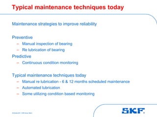
  • 3. 05 October 2011 © SKF Group Slide 2 Typical maintenance techniques today Maintenance strategies to improve reliability Preventive – Manual inspection of bearing – Re lubrication of bearing Predictive – Continuous condition monitoring Typical maintenance techniques today – Manual re lubrication - 6 & 12 months scheduled maintenance – Automated lubrication – Some utilizing condition based monitoring
  • 4. 05 October 2011 © SKF Group Slide 3 1Main Bearing Inspection and Maintenance
  • 5. 05 October 2011 © SKF Group Slide 4 Example 3 point bearing system Increasing number of main bearing failures in the market Root cause still under investigation Lubrication is one possible cause Heavy loads on Down wind side of bearing Light load on upwind side of bearing Upwind Side Load Zone
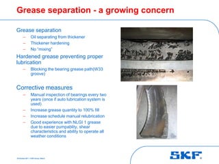
  • 6. 05 October 2011 © SKF Group Slide 5 Grease separation - a growing concern Grease separation – Oil separating from thickener – Thickener hardening – No “mixing” Hardened grease preventing proper lubrication – Blocking the bearing grease path(W33 groove) Corrective measures – Manual inspection of bearings every two years (once if auto lubrication system is used) – Increase grease quantity to 100% fill – Increase schedule manual relubrication – Good experience with NLGI 1 grease due to easier pumpablity, shear characteristics and ability to operate all weather conditions
  • 7. 05 October 2011 © SKF Group Slide 6 Manual Inspection of Bearing On Models that the front cover can be removed Grease – Condition and amount – Grease path – Grease Samples – Remove old grease Bearing – Measure internal clearance – Inspect inner and outer of bearing for damage (spalling, fragment denting, etc) – Inspect rollers (Smearing on face, fragment denting, etc)
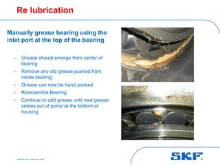
  • 8. 05 October 2011 © SKF Group Slide 7 Re lubrication Manually grease bearing using the inlet port at the top of the bearing – Grease should emerge from center of bearing – Remove any old grease pushed from inside bearing. – Grease can now be hand packed – Reassemble Bearing – Continue to add grease until new grease comes out of portal at the bottom of housing
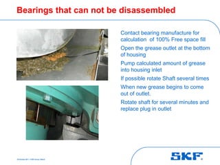
  • 9. 05 October 2011 © SKF Group Slide 8 Bearings that can not be disassembled Contact bearing manufacture for calculation of 100% Free space fill Open the grease outlet at the bottom of housing Pump calculated amount of grease into housing inlet If possible rotate Shaft several times When new grease begins to come out of outlet. Rotate shaft for several minutes and replace plug in outlet
  • 10. 05 October 2011 © SKF Group Slide 9 Auto Lubrication Systems Benefits of Auto Lubrications – Small amount of grease added often (1 minute every 6 hours) – Reduced heat – Reservoir will hold enough grease for a year or more – Using the IFM module grease will be added only while turbine is operating – Reduced cost Less waste, buy in bulk, reduced man hours
  • 11. 05 October 2011 © SKF Group Slide 10 Summary - Main Bearing Inspection and Maintenance  Root cause failure still under investigation, Lubrication is one possible cause  Recommend manual inspection every 2 years if continuing with manual re lubrication  Recommend manual inspection before installing auto lubrication system  Small amount of grease added daily reduces heating, oil separation (hardening), Improves oil film.  Proper lubricating procedures will increase bearing life
  • 12. 05 October 2011 © SKF Group Slide 11 2Main Bearing Condition Monitoring
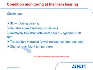
  • 13. 05 October 2011 © SKF Group Slide 12 Condition monitoring at the main bearing Challenges, Slow rotating bearing Variable speed and load conditions Relatively low shaft rotational speed – typically < 20 rpm Transmitted vibration (tower resonance, gearbox, etc.) Changing ambient temperature All points influence the vibration values
  • 14. 05 October 2011 © SKF Group Slide 13 Methods for predictive maintenance Different methods/techniques used to measure the condition, Temperature Lubrication (grease) analysis Overall Vibration values Spectral analysis Main bearing and rotor Main bearing
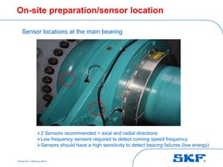
  • 15. 05 October 2011 © SKF Group Slide 14 On-site preparation/sensor location 2 Sensors recommended > axial and radial directions Low frequency sensors required to detect running speed frequency Sensors should have a high sensitivity to detect bearing failures (low energy) Sensor locations at the main bearing
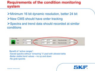
  • 16. 05 October 2011 © SKF Group Slide 15 Requirements of the condition monitoring system Minimum 16 bit dynamic resolution, better 24 bit New CMS should have order tracking Spectra and trend data should recorded at similar conditions Benefit of “active ranges”: -Saved spectra without “smearing” if used with allowed delta -Better stable trend values – no up and down -No grab spectra
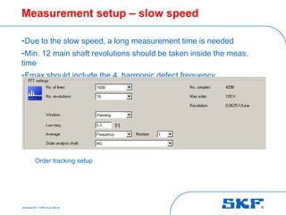
  • 17. 05 October 2011 © SKF Group Slide 16 Measurement setup – slow speed -Due to the slow speed, a long measurement time is needed -Min. 12 main shaft revolutions should be taken inside the meas. time -Fmax should include the 4. harmonic defect frequency Order tracking setup
  • 18. 05 October 2011 © SKF Group Slide 17 Example of a main bearing defect Turbine data: -1.5 MW turbine -Life time 9 years -Onshore -Three point bearing design (1 main bearing / gearbox) -Spherical Roller Bearing -Similar to several main bearing defects
  • 19. 05 October 2011 © SKF Group Slide 18 Comparison of different trend data velocity trend acceleration trend Overall trends are not reliable to track main bearing issues. Good for rotor/blades and tower vibration Gearbox and main bearing changed 12.03.09
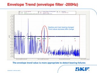
  • 20. 05 October 2011 © SKF Group Slide 19 Envelope Trend (envelope filter -200Hz) Gearbox and main bearing changed Trend values decrease after change The envelope trend value is more appropriate to detect bearing failures
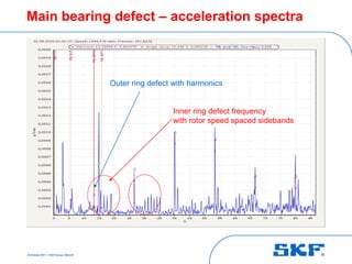
  • 21. 05 October 2011 © SKF Group Slide 20 Main bearing defect – acceleration spectra Outer ring defect Outer ring defect with harmonics Inner ring defect frequency with rotor speed spaced sidebands
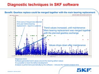
  • 22. 05 October 2011 © SKF Group Slide 21 Diagnostic techniques in SKF software First overrun frequencies detected One year before bearing replacement – report to customer Trend values increased, until maintenance Main bearing replacement was merged together with the planned gearbox exchange Values drops down after maintenance Benefit: Gearbox replace could be merged together with the main bearing replacement Diagnosis trend: Software generated band values around the bearing defect values It is possible to track the defect development Analysis is performed automatically by the software – reduces the needed analysis time
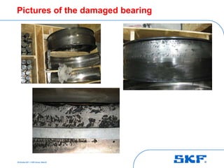
  • 23. 05 October 2011 © SKF Group Slide 22 Pictures of the damaged bearing
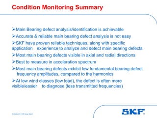
  • 24. 05 October 2011 © SKF Group Slide 23 Condition Monitoring Summary Main Bearing defect analysis/identification is achievable Accurate & reliable main bearing defect analysis is not easy SKF have proven reliable techniques, along with specific application experience to analyze and detect main bearing defects Most main bearing defects visible in axial and radial directions Best to measure in acceleration spectrum Most main bearing defects exhibit low fundamental bearing defect frequency amplitudes, compared to the harmonics At low wind classes (low load), the defect is often more visible/easier to diagnose (less transmitted frequencies)
  • 25. 05 October 2011 © SKF Group Slide 24 Next Steps……. Connecting Technologies…..
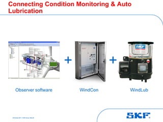
  • 26. 05 October 2011 © SKF Group Slide 25 Connecting Condition Monitoring & Auto Lubrication + + WindCon WindLubObserver software
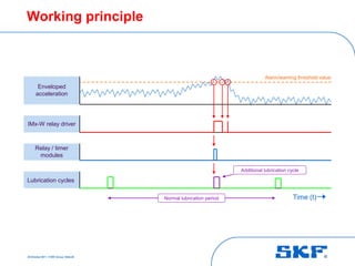
  • 27. 05 October 2011 © SKF Group Slide 26 Working principle Enveloped acceleration IMx-W relay driver Time (t) Lubrication cycles Alarm/warning threshold value Normal lubrication period Relay / timer modules Additional lubrication cycle
  • 28. 05 October 2011 © SKF Group Slide 27 Thank you – any questions please ?