1. Introduction
Martensitic stainless steels (MSSs) are generally selected for applications combining high strength and corrosion resistance under ambient atmospheric conditions [
1]. Common applications of MSSs (based on the Fe-Cr-C ternary system) comprise steam, gas, and jet engine turbine blades that operate at relatively low temperatures, steam pipes, large hydro turbines, freshwater canal locks, pipes and valves for petroleum gathering and refining, and cladding for continuous caster rolls [
1]. Such steels show a wide yield strength range, varying from 275 MPa (for elongation of 20% in an annealed condition) to 1900 MPa (for elongation of 2% in the quenched and tempered condition), the former occurring for the 403 grade (with relatively low carbon content, namely 0.15 wt. % C) and the latter occurring for high-carbon grades (in this case, for the AISI 440C one) [
1]. It is also worth mentioning that the relatively low-chromium and low-alloying element content of the MSSs makes them less costly than the other stainless steel types [
1].
The highest carbon and chromium contents of the AISI (American Iron and Steel Institute) 400 series MSSs are presented in the 440 grades. According to Lippold and Kotecki [
1], the AISI 440 grades are subdivided into 440A (constituted of 0.60–0.75 wt.% C and 16.0–18.0 wt.% Cr), 440B (0.75–0.95% C and 16.0–18.0% Cr), and 440C (0.95–1.20% C and 16.0–18.0% Cr). These steels were developed for applications where high hardness, wear resistance, and corrosion resistance are required. Critical applications of AISI 440C-grade MSS subjected to harsh working conditions can be observed in bearings used in cryopumps of space engines with liquid cryogenic LH
2/LO
2 propellants. Such application has led to the recent development of new materials, as in the case of the high-nitrogen martensitic stainless steels, where a newly developed steel modifies the currently used AISI 440C steel in the above-mentioned application by partial substitution of carbon with nitrogen [
2].
The AISI 440C MSS metallurgical behavior as a function of the applied heat treatment has been mainly investigated regarding the austenitizing temperature and the different heating conditions, leading to partial or total solution of the steel alloying elements into the stable-austenite field [
3,
4]. Special attention has also been dedicated to the sub-zero treatment practice, aiming to partially or totally suppress the presence of the retained austenite in the steel microstructure [
5]. And, despite the widespread application in various industrial fields due to the excellent AISI 440C MSS physical and chemical properties [
6], surface strengthening methods have been studied aiming to enhance its surface performance since surface and subsurface failure tend to always take place over conditions of long-term service, in accordance with Harris and Kotzalas (2006), as observed in Ref. [
6].
The expected hardness and strength of the as-hardened AISI 440C MSS make it a possible candidate for cavitation-erosion application purposes. This assumption is based on the very well-established results of Hattori and Ishikura, which show that the cavitation-erosion resistance (ER) for different stainless steels can be reliably estimated from the hardness of the material through Equation (1) [
7]:
ER is expressed in h μm
−1 and defined as the reciprocal value of the maximum mean depth of erosion rate; HV, the Vickers hardness; and
Fmat, the material factor obtained from the hardness ratio of the original surface to that of the eroded surface after an erosion test.
From Equation (1) [
7], it is clearly shown that the higher the hardness, the higher the material erosion resistance.
The great interest of several engineering areas in the cavitation phenomenon has led the investigation on cavitation mechanisms to be significantly increased in different stainless steels in the last years [
8,
9,
10,
11,
12], since Bogachev and Mints’ discoveries on the concept (principle) of metastability of austenite [
13], comprising different types of materials and treated surfaces [
8,
9,
10,
11,
12,
13,
14,
15,
16,
17,
18]. Regarding the AISI 440C MSS, research efforts have been mainly made aiming to investigate the effect of the application of surface treatments on the substrate materials, as shown in Refs. [
19,
20]. As presented in Ref. [
10], the Bogachev and Mints’ concept (principle) of metastability of the austenite principle predicts that the low energy of packing defects in the austenite under loading leads it to present intense γ→ε→α′ martensitic transformation, being such transformations accompanied by stress relaxation at the moment of the diffusion-free rearrangement of the crystal lattice, ensuring high resistance to cavitation and erosion fracture [
13].
By this way, recently, the effective role of the austenite phase on the typical cavitation stages (incubation, acceleration, and maximum erosion rate, but excluding the deceleration stage, such as considered in Ref. [
14]), occurring in the microstructure of several classes of stainless steels, had its investigation initiated for surfaces subjected to cavitation tests [
8,
9,
10]. In this case, using a deepened characterization via X-ray diffractometry (XRD) technique alternated with cavitation-erosion tests for increasing times, in the same surface region of a specific sample, two distinct types of austenite phases were initially studied, namely, the reversed austenite as the second phase dispersed in an ASTM (American Society for Testing and Materials) CA-6NM grade low-carbon MSS [
8,
10], and the thermally stable austenite as the matrix phase of a solution-treated AISI 304 grade austenitic stainless steel (ASS) [
9,
10]. It should be noted that the austenite phase in the AISI 304 ASS is, in fact, metastable for a significant level of deformation, as confirmed by the results in Refs. [
9,
10]. In such cases, the utilized procedure was strong enough to significantly determine, for the first time, the mechanism that precedes the erosive wear, defining the incubation-acceleration stage transition as well as the cavitation-affected depth for the occurrence of the γ(austenite)→α′(martensite) strain-induced transformation into the material microstructure for each studied steel [
9,
10]. It was concluded that such mechanisms cover deformation of the steel matrix and strain-induced transformation of the austenite to martensite at surfaces subjected to cavitation, strongly influencing the beginning of the significant mass loss process for the studied low-carbon stainless steels.
One last aspect to also consider on this subject concerns stacking fault energy (SFE), as it is normally used to predict deformation mechanisms in austenitic steels [
21,
22]. As presented in [
21], for SFE higher than 30 mJ m
−2, dislocation slip prevails and dynamic recovery softens the material. For SFE lower than 30 mJ m
−2, alternative deformation mechanisms may be activated, namely mechanical twinning and strain-induced martensite formation, leading to significant microstructural refinement and superior strain-hardening [
22]. In such a case, martensite formation is predicted for steels with SFE ≤ 20 mJ m
−2, deformation twinning for SFE ~15–30 mJ m
−2, deformation twinning and martensite formation in the range of 15–20 mJ m
−2, and dislocation slip when SFE ≥ 30 mJ m
−2 [
22].
So, a similar investigation procedure to that used in the Refs. [
8,
9,
10] by intercalating cavitation tests with XRD characterization in the same specific region subjected to cavitation was applied here. It aims to bring light to the study on the behavior of the retained austenite and carbide phases of a high-carbon AISI 440C martensitic stainless steel in an as-hardened condition, being retained austenite, the third type of austenite studied by the authors on the present subject.
2. Materials and Methods
Cylindrical samples of 50.8 mm diameter × 10 mm height were cut from an annealed AISI 440C MSS bar, showing a composition of 1.045% C, 16.98% Cr, 0.28% Ni, 0.03% Mo, 0.79% Mn, 0.901% Si, 0.014% P, 0.007% S, and Fe balance (for values expressed in wt.%, obtained via optical emission spectrometry).
Four distinct sets (sets 1–4) of samples were heat treated (each one comprising a different cooling condition from the austenitizing temperature at 1050 °C). The heating procedure of the samples was divided into three steps (as presented in
Table 1), aiming to provide better and faster temperature homogenization of the samples and decrease the risk of heating crack formation. The relatively longer soaking time of 60 min aimed for a more effective dissolution of carbides presented in the steel microstructure.
Samples of set 1 were subjected to air-cooling in the final step of the hardening treatment (being termed ‘air-hardened’ hereafter) and showed a hardness of 810 ± 24 HV
0.3 and a bct martensite matrix. After that, some samples were also subjected to the tempering treatment (at 220 °C for 1 h, as indicated in Refs. [
18,
23]), showing a 734 ± 17 HV
0.3 average hardness value, thus constituting the second set of samples (set 2, being termed ‘air-hardened and tempered’ hereafter). For sets 3 and 4, the samples were cooled in liquid nitrogen (promoting cryogenic or sub-zero quenching) for 10 min and 24 h, respectively. Both the samples of set 3 and set 4 presented practically the same average hardness value of 821 ± 19 and 822 ± 16 HV
0.3, respectively, showing slightly higher average hardness values than the samples of set 1. The sample surfaces for the cavitation-erosion test were prepared using 120–1200 grade SiC sandpaper and polished with a 1 µm Al
2O
3 abrasive suspension.
The detailed procedure of the XRD characterization used to estimate the retained austenite (γ
RET) and martensite (α′) phase volumetric fractions on the studied surfaces is presented in Refs. [
8,
9]. The XRD pattern measurements were carried out using a Shimadzu XRD7000 diffractometer (Kyoto, Japan), with Cu-Kα radiation (λ = 1.5406 Å), in the θ−2θ (Bragg-Brentano) configuration, to 38–52° 2θ angle range, 0.5° min
−1 scan speed, and 0.02° step. In the present work, XRD characterizations were intercalated with cavitation-erosion tests in the same position at the surface of a specific air-hardened sample for increasing test times all over its incubation period, aiming to investigate the behavior under cavitation of the main constituents of the AISI 440C MSS microstructure (namely the steel martensite matrix, the retained austenite, and the dispersed chromium carbide particles). With this procedure, it was possible to determine the evolution of the estimated γ
RET fraction within the specific cavitated area as a function of the 0–500 min range cavitation test times, given support to determine how long time was needed to promote the strain-induced martensitic transformation at the high-carbon MSS surface microstructure studied here.
In addition, the microstructure of the studied air-hardened samples, revealed with Marble’s reagent (4 g of Copper Sulfate II + 20 mL of hydrochloric acid + 20 mL of water), was characterized by means of optical microscopy (OM) using an Olympus BX51M microscope (Tokyo, Japan). Vickers hardness characterization was performed using Shimadzu HMV-2T equipment (Kyoto, Japan), with load of 300 g and loading time of 15 s. The aspect of the cavitated surfaces of air-hardened samples was observed for different testing times all over the test by scanning electron microscopy (SEM) using a TESCAN LMU Vega 3 microscope (Brno, Czech Republic). All cavitation erosion tests were carried out through the indirect method, in accordance with the ASTM G32-10 standard [
24], using 20 kHz ultrasonic vibratory equipment with peak-to-peak displacement amplitude of 50 μm in distilled water. The temperature of 25.0 ± 2.0 °C of the test liquid near the specimen was controlled by a thermocouple immersed in the bath, using a cooling bath with thermostatic control around the test liquid-containing vessel. Finally, the mass measurements aiming to determine the cumulative mass loss (CML)–time curve were carried out with an analytical balance of 0.01 mg accuracy. Additional details of the applied cavitation-erosion test technique can be found in Refs. [
10,
18].
3. Results
The results of the AISI 440C MSS cavitation study are presented in
Figure 1a–d.
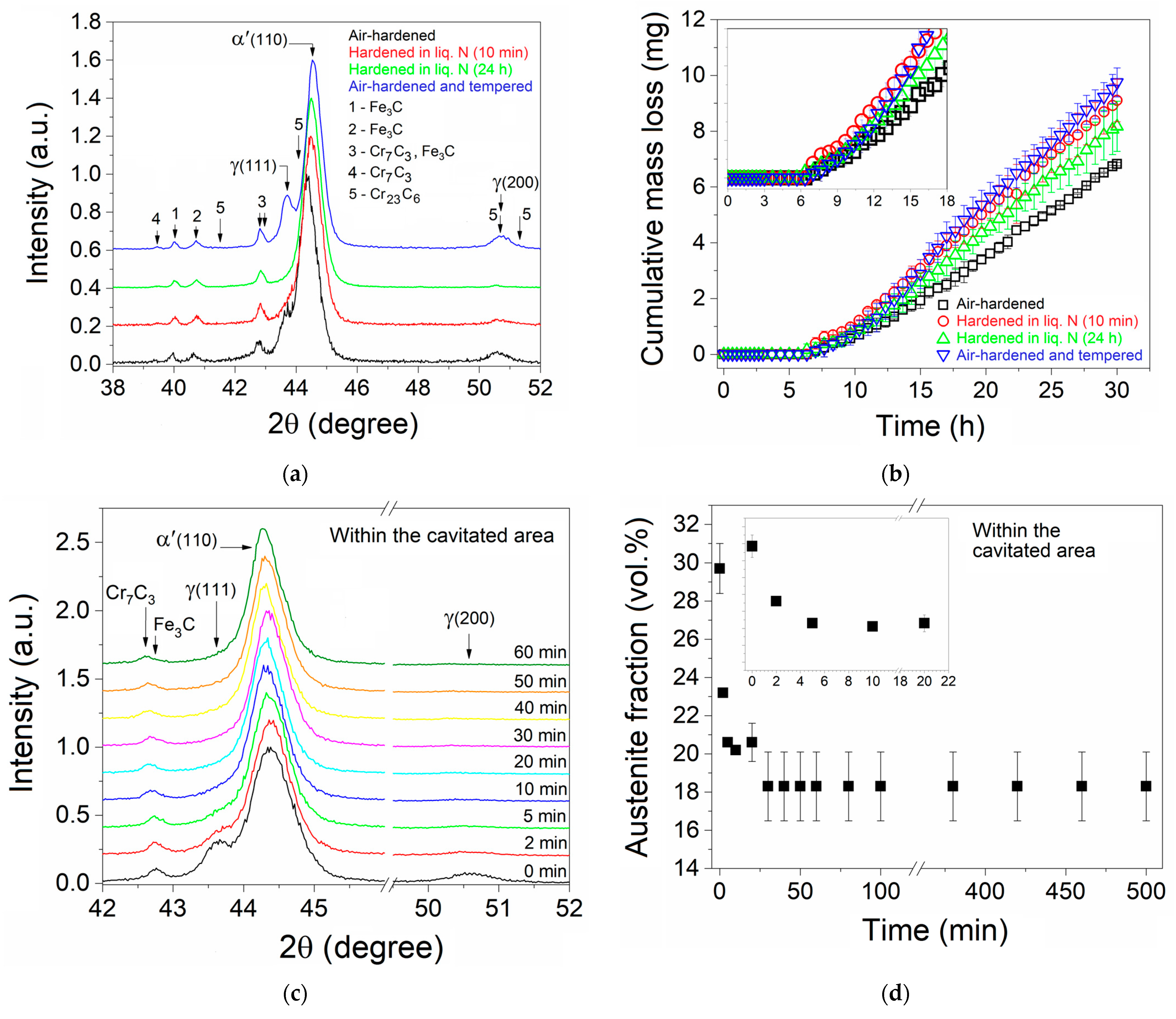
Figure 1a shows the XRD patterns that were obtained to determine the microstructure constituent phases of the four distinct steel heat treatment conditions considered here. Five distinct phases can be observed in the obtained XRD patterns, namely the martensite matrix (α′), retained austenite (γ
RET), cementite (Fe
3C), and Cr
23C
6 and Cr
7C
3 chromium carbides, confirmed through the JCPDS (Joint Committee on Powder Diffraction Standards, now ICDD: The International Centre for Diffraction Data) card pdf No. 44-1290, 33-397, 34-0001, 35-0783, and 11-0550, respectively.
Using the same semi-quantitative analysis method from Tanaka and Choi [
25], as shown in Ref. [
8], for the estimation of the γ
RET fraction presented in the air-hardened (set 1) sample, a value of ~30 vol.% γ
RET was obtained, these values agreeing well with those indicated in Ref. [
23]. The above-mentioned analysis method uses the integrated intensity under both the main austenite (γ-phase) and martensite (α′-phase) diffraction peaks (referred to as the respective 100% intensity peaks). It is worth mentioning that this estimate made here is only approximate since the applied method does not consider the occurrence of the other phases of the steel microstructure, such as the iron carbide and chromium carbide (according to
Figure 1a results), so it only serves a rough comparative purpose. For the samples of set 3 (hardened in liq. N for 10 min) and set 4 (hardened in liq. N for 24 h), similarly, it was estimated that the γ
RET fraction decreased to ~16 and ~10 vol.%, respectively, agreeing well with the reported in Refs. [
23,
24], and as expected for steels showing their final martensite temperature (M
f) below the room temperature, which is the case here. For the as-tempered samples, the typical stress relief of the martensite matrix surrounding the austenite phase grains during its tempering treatment leads part of the retained austenite to be additionally transformed into martensite. It should be remembered that the γ(austenite)→α′(martensite) transformation occurs with an increment of ~4 vol.%, so, as the martensite phase of the steel matrix is brought to a more ductile state during its tempering treatment, part of the retained-austenite can be expanded in volume, which explains its transformation to an additional martensite volumetric fraction, as expected for high-alloy steels. For this case, the γ
RET fraction of the air-hardened and tempered samples (set 4) was estimated to be ~24 vol.%, thus showing a decrease of ~6 vol.% with regards to the γ
RET fraction of the air-hardened samples.
Figure 1b presents the cumulative mass loss as a function of the cavitation test time for the studied samples. The
Figure 1b data have led to the obtainment of
Table 2, which shows the cavitation-erosion data for the distinct AISI 440C MSS sample conditions, comprising the cumulative mass loss (CML), the average erosion rate (AER), and the mean erosion depth (MED). In brief,
Table 3 presents the incubation period (IP), nominal incubation period (PIN), maximum erosion rate (MER), and experimental erosion resistance (ER
Exp) for the distinct AISI 440C MSS conditions, also determined from the
Figure 1b results. In a generic way, all these results show slightly better cavitation-erosion behavior for the air-hardened (set 1) samples, being that the other three studied conditions have distinct particularities depending on their hardness and γ
RET volume fraction, as discussed ahead.
Figure 2 shows the OM and SEM results for the tested air-hardened sample.
Figure 1c shows the air-hardened sample XRD patterns within the same cavitation-tested area for times of 2, 5, 10, 20, 30, 40, 50, and 60 min (the zero corresponding to the original or non-tested surface), obtained by intercalating the XRD characterization and cavitation-erosion test, as previously indicated. It is worth mentioning that the shoulder referred to the γ-phase (111) peak (in this case, the retained austenite) seems to disappear for a cumulative test time between 20 and 30 min, being that the same is observed for the γ-phase (200) peak for a 20 min cumulative test time.
Figure 1d presents the evolution of the estimated γ
RET fraction within the cavitated area as a function of the 0–500 min cavitation test time. It is shown that the γ
RET fraction decays from ~30 (the initial condition for the non-subjected surface region to cavitation test) to ~20–18 vol.% as the specific region was tested for a cumulative time equal to or longer than ~20–30 min, respectively, confirming the γ
RET (austenite) → α′ (martensite) transformation as a direct consequence of the cavitation efforts in the specific tested area. It is also shown from the
Figure 1c,d results that in just ~5 min of cavitation test time, practically all the transformation capacity of the surface was attained (leading the γ
RET fraction to decay from ~30 to ~20 vol.%).
Figure 2a shows the microstructure obtained via OM for the air-hardened sample using Marble’s reagent. It is also shown in the SE–SEM micrographs of the non-tested surface just after the polishing procedure (
Figure 2b) and surfaces subjected to 60, 120, 180, 420, 900, and 1800 min of cavitation test time (
Figure 2c–h), respectively.
The obtained microstructure (see
Figure 2a) of the air-hardened (set 1) samples is constituted of a martensitic matrix with ~30 vol.% γ
RET, showing a slight precipitate interconnected net formation in the grain boundaries of the prior (parent) austenite, possibly constituted of the M
7C
3 (C
2 carbide)-kind phase, besides carbide phases with two distinct morphologies. Differently, the polished surface, prepared for the cavitation test, clearly shows a smoothed and cleaned surface, as expected (see
Figure 2b).
On the other hand, the results obtained for surfaces subjected to 60, 120, 180, 420, 900, and 1800 min of cavitation test time clearly show two distinct morphology types: one for surfaces tested up to 420 min (see
Figure 2c–f), and the other one for surfaces tested for times longer than 420 min (see
Figure 2g,h). For the former group of results considered here, even for a test time as long as 420 min (
Figure 2f), one can still observe the maintenance of the original plane of the tested surface since it is not totally eroded, unlike the latter group of results, for which a surface is totally cavitation-eroded (see
Figure 2g). In addition, along the first 420 min, already observed at 60 min (
Figure 2c), it can be noted the pit occurrence, suggesting that the carbide phases are firstly removed by the cavitation efforts, being torn from the tested surface area as the cavitation test is carried out. It can also be observed for the 60 min test time (
Figure 2c) that the grain boundaries of the prior austenite also begin to be cavitation-attacked. The same behavior seems to be continuously observed for the surfaces tested for 120 and 180 min (
Figure 2d and
Figure 2e, respectively), with the refined carbides at the prior austenite grain boundaries being torn. Such behavior is strongly intensified for the 420 min tested surface (
Figure 2f), for which larger craters along the grain boundaries seem to be present. In all these cases, only a slight apparent deformation is presented, which is due to the high hardness and strength of the studied steel condition. Finally, for the second group of results here, craters are presented in profusion, indicating the complete erosion of the original studied surfaces.
4. Discussion
Two main aspects can be depicted by comparing the XRD results shown in
Figure 1a. First, both the air-hardened (set 1) and the air-hardened and tempered (set 2) samples clearly show peaks of the austenite phase, indicating that the retained austenite (γ
RET) phase is presented in the microstructure of the steel in significant amounts, mainly confirmed by the γ(200) peak that shows relatively high intensity for both cases. Second, samples cooled under liquid nitrogen (−195.8 °C) and maintained for 10 min (set 3) and 24 h (set 4) showed a strong reduction in the peak intensities of the austenite phase, as typically expected for the AISI 440C MSS when subjected to sub-zero hardening treatment using liquid nitrogen.
Regarding the two carbide morphologies observed in the microstructure of the 1050 °C air-hardened samples (set 1), as shown in
Figure 2a, the coarsened (primary) carbides were formed during the alloy solidification process, non-dissolved, and kept in equilibrium at the austenitizing temperature along with the soaking time of the hardening treatment, according to Ref. [
26]. On the other hand, the refined (secondary) carbides were attained during the air-cooling step, from the austenitizing temperature to the room temperature, as the hardening treatment was carried out. It is to be remembered that with the decrease in temperature, the carbon solubility in the austenite phase is diminished, resulting in additional carbide precipitation in this case. This assumption is supported by results showing the temperature influence on the carbon solubility (in the γ phase/field) and precipitation (γ + M
23C
6 field) boundary for an iron alloy with 18 wt.% Cr (considering the solubility curve for 0% Ni), after Tama, Vyklicky, and Löbl (1970) and after Gerlach (1970), as presented in Ref. [
26].
In addition, according to the ternary Fe-Cr-C constitution diagram at 17% Cr (after Castro and Tricot (1966), shown in Ref. [
26]), the sequence of solidification of the 1.0% C alloy for equilibrium condition is (L) → (L + γ) → (L + γ + C
2) → (γ + C
2) → (γ + C
1 + C
2) → (γ + C
1) → (δ + γ + C
1) → (α + C
1), being the mixed iron–chromium carbides, C
2 = M
7C
3, and C
1 = M
23C
6. It should be noted in this referred ternary diagram that no M
7C
3 (C
2 carbide) phase is observed below 800 °C, differently from the results observed in
Figure 1a. Such differences could be attributed to differences in the chemical composition, considering that steel is a complex alloy with multiple components, and mainly to the solid-state transformation kinetics. Even so, it is worth mentioning that the air-hardened sample microstructure obtained here is similar to that shown in Ref. [
3]. In that work, the calculation of equilibrium phases of the AISI 440C MSS with nominal composition of Fe–17.0Cr–1.0C–1.0Si–1.0Mn–0.75Mo at the 1052 °C austenitizing temperature indicated the presence of austenite as the matrix phase associated with two carbides, namely the M
23C
6 and M
7C
3. Another result showing that both the M
7C
3 and M
23C
6 phases can be presented in the microstructure of the AISI 440C MSS alloy is also indicated in Ref. [
27]. For the matrix of an AISI 440C alloy processed by electroslag remelting, besides the M
23C
6 carbide, it also presented fine Cr
7C
3 precipitates.
The assumption regarding the beginning of an interconnected precipitate net formation constituted of the M
7C
3 (C
2 carbide) phase, spread all over the martensitic matrix (see
Figure 2a) and also in the prior austenite grain boundaries, is supported by the fact that such a phase would be stable at the 1050 °C austenitizing temperature. This assertion is in accordance with the phase field (γ + C
1 + C
2) of the ternary alloy Fe-17Cr-1.0C (after Castro and Tricot (1966) in Ref. [
26]), as above-mentioned, as well as by the results of the Ref. [
3], from the calculations indicating the occurrence of increasing M
7C
3 (C
2 carbide) phase fractions in the AISI 440C MSS samples at the austenitizing temperatures varying on the ~1010–1093 °C range. Aiming to confirm this premise, Thermo-Calc (Stockholm, Sweden) was used to determine the possible phases, compositions, and their respective fractions, considering the material of set 1’s samples in equilibrium at the austenitizing temperature of 1050 °C. In this case, volume fractions of 0.91059, 0.08918, and 0.00023 were obtained for the austenite (fcc), M
7C
3, and MnS phases, respectively, as depicted in
Figure 3, which shows the volume fraction of phases as a function of the temperature obtained for the specific composition of the AISI 440C MSS used in this work. It can be observed in
Figure 3 that at the austenitizing temperature of 1050 °C, the M
7C
3 carbide is thermodynamically stable, which means that an important fraction of the carbon content of the studied alloy is not in solid solution in the austenite. The estimated actual carbon content dissolved in the austenite phase as well as its composition at 1050 °C are, in this case, 0.343% C, 0.305% Ni, 12.504% Cr, and Fe balance (for values expressed in wt.%). It is worth mentioning that the identification and respective constitution of the possible two kinds of carbides, namely M
7C
3 and M
23C
6, were not determined in the present work. If interesting, such characterization can be carried out using higher-resolution SEM images and EDS, as recently observed for both the kinds of carbides presented in a high-carbon and high-chromium-containing cold work tool (the AISI D2) steel (see Ref. [
28]). It should be emphasized that the AISI D2 tool steel contains in its composition ~1.5% C and 11.25% Cr, besides other carbide-former alloying elements, but in very smaller amounts, in the case of 0.8% V and 0.8% Mo, thus differing from the AISI 440C MSS, which shows 1.045% C and 16.98% Cr in its composition.
Regarding the cavitation behavior of the carbide phases (see
Figure 2c–f results), the pit occurrence suggests that carbides tend to be initially removed under the cavitation action. In accordance with Ref. [
19], the cavitation erosion attack would be initiated at the boundaries of large carbides, which seem to be liable to cracking under cavitation attack. In addition [
19], as the matrix around the carbides is eroded away, carbides lose support and are eventually dislodged out of the sample. In the AISI 440C MSS samples studied here, the relatively high hardness of the matrix would delay this removal effect under the cavitation efforts since the cavitation erosion resistance is directly related to the hardness of the matrix, according to the Hattori and Ishikura results [
7], as previously discussed.
Concerning the retained austenite, this phase is difficult to distinguish from the martensite phase with the metallographic procedure used in
Figure 2a. For its better identification, the use of the EBSD and/or TEM techniques, as shown in Refs. [
15,
16,
17], would be more indicated. It should be remembered that the occurrence of such phase is directly related to the low carbon solubility in the ferrite as well as in the martensite, which forces carbon partitioning in the austenite (after Gennari et al., 2020, in Ref. [
29]), being the residual austenite phase able to transform at room temperature into martensite during loading as either stress- (i.e., elastic) or strain- (i.e., plastic)-induced transformation mechanisms [
29]. The results in
Figure 1b,
Table 2 and
Table 3, can be explained together considering the role of the retained austenite (γ
RET) phase and the material hardness on the cavitation-erosion resistance, as previously indicated in Ref. [
7]. Regarding the cavitation-erosion behavior of the four studied AISI 440C MSS sample conditions, two distinct groups can be observed: one presenting higher retained austenite (γ
RET phase) fractions, namely those of the set 1, and two samples, and the other one showing smaller γ
RET phase fractions, namely the set 3, and four samples. Analyzing the former group, the role of the γ
RET phase on the AISI 440C MSS cavitation-erosion behavior is emphasized. This assertion is based on comparing the data obtained for samples of set 1 (air-hardened/~810 HV/~30% γ
RET) and set 2 (air-hardened and tempered/~734 HV/~24% γ
RET), since it is noticed that both the samples of set 1 (air-hardened) and 2 (air-hardened and tempered) presented practically identical IP (and NIP), even keeping in mind the smaller hardness for the samples of set 2, thus confirming the premise regarding the role of the γ
RET phase. But, differently, the set 2 condition apparently presented the worst behavior in the maximum erosion rate stage considering all four studied conditions, revealing the significance of the hardness of the stainless steel on the erosion behavior, which is in agreement with the Hattori and Ishikura results [
7]. On the other hand, for the latter group, an intermediary behavior in the maximum erosion rate stage between those verified for the set 1 and 2 samples was observed, which is also directly related to the sample hardness, namely for the set 3 (liq. N-10 min/~821 HV/~16% γ
RET) and 4 (liq. N-24 h/~822 HV/~10% γ
RET) samples, both showing the highest hardnesses of all studied sets of samples but smaller γ
RET phase fractions than the set 1 samples (air-hardened ones).
Another aspect to be discussed is related to the mechanism by which the retained austenite in the studied samples was transformed to martensite, as observed from the
Figure 1c–d results. For this purpose, the fact that with only ~5 min of cavitation test time, practically all the transformation capacity of the surface was attained (see
Figure 1d) deserves special attention. This result seems to be directly related to the relatively high hardness of the obtained microstructure in the air-hardened AISI 440C MSS condition, which makes it difficult for a higher transformation volume of the γ
RET phase to be attained under cavitation effects. As expected, in this case, the higher the hardness, the higher the strength, and the lesser the ductility of the considered surface. Note that in Refs. [
8,
9,
10], strain-induced transformation under cavitation was considered to be the main mechanism acting on the austenite phase behavior of a soft martensitic stainless steel (termed ‘reversed austenite’, in the as-tempered ASTM CA-6NM MSS samples with a hardness of 300 ± 20 HV
0.3 [
8]) as well as in a typical austenitic stainless steel (in this case, in solution-treated AISI 304 ASS samples, mainly constituted by ‘thermally-stable austenite’ at room temperature, with a hardness of 190 ± 6 HV
0.3 [
9]). In both cases, the assumption of the strain-induced transformation mechanism, as indicated in Refs. [
8,
9,
10], was in strong agreement with the relatively low hardness of the both investigated steel matrixes as well as with the relative high capability of their surfaces to plastically deform, based on the respective observed surface morphologies, confirming the significant increase in deformation of both the soft martensitic and austenitic matrixes as a function of the cumulative cavitation test time. But, in the present investigation, the air-hardened AISI 440C MSS substrates are far from being ductile, showing a hardness of 810 ± 24 HV
0.3, which is comparatively ~3, and ~4 times higher than the hardness of the ASTM CA-6NM MSS and AISI 304 ASS samples, respectively. Thus, it seems that, differently from what was observed for both the referred ASTM CA-6NM and AISI 304 stainless steels, in which their matrixes presented significant plastic deformation under cavitation efforts, the action of the cavitation-shock waves and the microjets impinging on the surface and entering into the substrate bulk of the air-hardened AISI 440C MSS samples would supposedly lead the martensite matrix surrounding the austenite phase preferentially to deform in the elastic regime due to its relatively high hardness.
This assumption is supported by the apparent absence or very little presence of undulations (plastic deformation) formed on the cavitation tested surface along the incubation period for cumulative test times no longer than 420 min (see
Figure 2c–f), also indicating that for the 420 min test time (
Figure 2f), the cavitation acceleration stage has just initiated its working. In a continuous way, it seems that the cavitation efforts would preferentially lead the retained austenite crystals mainly to deform in the plastic regime due to the expected higher ductility of this phase. Keeping in mind the set of properties of both the martensite and austenite phases and considering the retained austenite crystal-martensitic matrix interfaces, one could infer that the austenite phase presented on the outermost surface of the AISI 440C MSS samples would preferentially be transformed, explaining the relatively short cavitation test time of 5 min to lead to a practically steady state on the austenite phase fraction in
Figure 1d. In addition, it could also be inferred that the strain-induced martensitic transformation of the retained austenite would be strongly assisted by the elastic deformation and relaxation-intermittent action of the harder martensitic matrix on the austenite crystals through the referred interfaces (supposedly solicited by elastic cyclic efforts with successive loading and unloading), both of which are direct consequences of the cavitation efforts on the material surface.
All such assumptions are jointly considered here, remembering that the austenite transformation to martensite happens with an increase of about 4 vol%, as predicted by Equation (2) after Lement (1959), as presented in Ref. [
30]. This means that the neighborhood of the austenitic phase, composed of the steel martensitic matrix, should allow such a volume change to occur, in this case. Thus, at least a small component of plastic deformation in the surrounding martensitic matrix should also be expected, as supposedly it occurs, and not only an elastic deformation component acting on the martensite phase. But additional efforts aiming to characterize the behavior under cavitation directly focused on martensite crystals surrounding the retained austenite phase should be demanded to confirm such an assumption.
Vγ
RET→α′ is the change in volume during transformation of the austenite to martensite; and %C, the carbon content expressed in wt.%.
The illustration of the cavitation effects (caused by the microjet impacts resulting from the collapsing bubbles and by the shock waves) on the target surface was previously presented in detail in Ref. [
10]. Such an illustration (see Ref. [
10]), supposedly valid for more ductile materials such as the AISI 304 austenitic stainless steel [
9] and the ASTM CA-6NM soft martensitic stainless steel [
8], shows two main distinct possible deformation regions: one, the outermost surface stressed above its yield stress, and the other, just below it, the region stressed at the elastic regime. Considering strong enough the assumption for which the martensitic matrix of the AISI 440C MSS samples is preferentially deformed in the elastic regime in the present case, the martensitic matrix phase at the outermost surface region would be preferentially subjected to stress levels lower than or close to its yield stress, thus mainly the austenite phase at the (outermost) surface would be subjected to stress levels higher than its yield stress. At least, this supposition would agree well with the
Figure 1d results. If interesting, one can access the basis of the mechanism for the strain-induced nucleation of martensitic transformations in Refs. [
31,
32,
33,
34].
Finally, the stacking fault energy (SFE) value of 15.0049 mJ m
−2 was obtained from the Equation (3), as predicted by Brofman and Ansell [
35], using the composition data of the prior (parent) austenite at the austenitizing temperature of 1050 °C, as theoretically estimated in
Figure 3. Considering that such composition (0.343% C, 0.305% Ni, 12.504% Cr, and Fe balance) can also be expected for the retained austenite (in fact, it is the same phase) but at the room temperature after the steel air-hardening treatment, from this obtained SFE value it could be inferred that both the mechanical twinning and strain-induced martensite formation mechanisms were effectively activated for the retained austenite in the AISI 440C MSS, in accordance with the SFE values on the 15–20 mJ m
−2 range, as previously indicated, which concludes the present discussion.


