


The world of wireless devices is rapidly spreading day by day. Ever since the invention of radios, different companies and research centers have had the same goal outlined for their engineers and scientists: create the most efficient, the most successful, and hence - the top selling radio module on the market. What defines a great radio module is not always easy to define, it usually depends of the task which the module has to solve.
In some situations, we need to send big chunks of data over a wireless network, in which case we usually don't ask for the energy consumption. In other situations, we have small portable devices which notify us of some occurrence, these devices use a battery for power, so the radio modules have to be as energy efficient as possible.
When we are talking about energy efficient radio modules, which can still send a suitable amount of data at a very cheap cost of energy consumption, one radio technology stands out: Bluetooth Low Energy.
When Bluetooth released the the Bluetooth 4.0 core specification, they introduced a new player on the field of radio modules: Bluetooth Low Energy (further: BLE), or sometimes called Bluetooth Smart. The BLE was actually started by Nokia, as a project once called "Wibree", and was introduced in 2006 under that certain name. In 2010, the Bluetooth Special Interest Group merged Wibree into the Bluetooth standard as a part of the 4.0 core specification. Although it is a part of the same specification, BLE alone is not backwards compatible with Bluetooth, and so we can not treat it as the same protocol as Bluetooth.
What makes BLE so special is that it can communicate with a large number of mobile devices find today, phones which run Android,OS X, Windows Phone, iOS and BlackBerry, as well as Linux, and Windows 8 all support BLE. Which means that you can integrate your project easily to make a multi-platformed communication. One reason for this is that BLE was created so that anyone with some data needed to be sent can use it anyhow they want, which was not the case with Bluetooth, which was conceived for special use cases. So imagine this: a radio module, fit for any data that is needing to be sent, energy efficient and connectable to all major platforms on the market... It is easy to see why BLE is the choice for low energy radio communication for most of today's engineers.
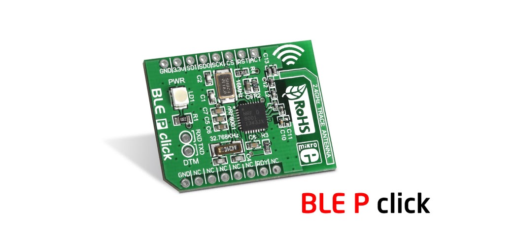
But enough chit chat, let's get down to the core of this, let's learn how BLE works and how we can implement it. In this part 1, we will go over the main used in BLE, we will see what it constitutes of, and talk about the data being transmitted over it. Part 2 will put all of this to use, as we will do a step by step tutorial on how to use our BLE P click to establish BLE connection between an MCU and an Android phone.

Data Throughput and Range
The modulation rate of the Bluetooth Low Energy radio is set by the specification at a constant 1Mbps (one mega bit per second). This, of course, is the theoretical upper limit. In practice, you can expect between 5-10 KB per second, depending on the limitations of the devices used. As far as range goes, BLE is focused on very short range communication. It’s possible to create and configure a BLE device that can reliably transmit data 30 meters or more line-of-sight, but a typical operating range is probably closer to 2 to 5 meters. Of course, the higher the range the more battery consumption, so take care when trying to tweak your device for higher range.
Overview: Building Blocks and Network Topology
Building Blocks of the BLE
BLE is organized in 3 major building blocks: Application, Host and Controller. Application block is, as the name says, the user application which interfaces with the Bluetooth protocol stack. The Host covers the upper layers of the Bluetooth protocol stack. And the Controller covers the lower layers. The Host can communicate with the BLE module with an addition of something we call HCI - the Host Controller Interface. The purpose of HCI is, obviously, to interface the Controller with the Host, and this interface makes it possible to interface a wide range of Hosts with the controller. In our case, the MCU runs the Application, and talks to a Connectivity Device, the Connectivity Device is made out the Host and Controller. For this purpose we use SPI to communicate, but different interfaces can also be used.
Network Topology
BLE devices can have two different roles, either as Central Devices or Peripheral Devices. Central devices are usually mobile phones or PC's which have a higher CPU processing power. While peripheral devices are usually some sensors or low power devices, which connect to the central device.
A BLE device can send two types of data: Advertising Packets, and Scan Response Data.
Advertising Packets are necessary, and are constantly being transmitted from a peripheral device in order to be seen by other devices. When other devices receive this data, they can request additional data from the peripheral device which then sends the Scan Response Data
A BLE device can talk to nearby devices in one of two ways: Broadcasting and Connections.
Broadcasting is the act of sending data out to all the listening devices. When talking about Broadcasting, we define two roles: Broadcaster and Observer. The Broadcaster sends non connectable advertising packets periodically to anyone who is willing to accept them. While the Observer repeatedly scans the area in order to receive the packets. Then, when the Observer receives the Advertising packet, it can request the Scan Response Data. It is important to note that Broadcasting is the only way a device can transmit data to more than one peer at a time.
 BLE Broadcasting Topology
A Connection is a permanent, periodical data exchange of packets between two devices. The master ( central device ) scans the frequencies for connectable advertising packets, and when suitable, initiates a connection. Once the connection is established, the central device manages the timing and initiates the periodical data exchanges. The slave ( peripheral device ) sends connectable advertising packets periodically and accepts incoming connections, once a connection is established the peripheral follows the central’s timing and exchanges data regularly with it. When connected, the two devices usually define what is known as a connection event. A connection event is a periodical exchange of data at certain specific points in time. This is one of the key benefits for power saving - two devices can power up, exchange data, and then go to sleep until the next connection event.
 BLE Connection Topology
BLE: Different Layers and their Purposes
BLE, like many other wireless technologies, is organized in a number of layers. Each layer has its purpose and plays a significant role in making a BLE device function properly. All the layers and definitions can look quite overwhelming, but we will take it step by step and cover all the necessary fields required to develop a successful project with BLE.
Let's take a look again at the 3 building blocks of a BLE device : Application, Host and Controller:
The Application, is the highest layer and the one responsible for containing the logic, user interface, and data handling of everything related to the actual use-case that the application implements. The architecture of an application highly depends on the project developed with BLE, so we will leave this part for the second part, when we will build a project with our BLE P Click.
The Host consists of the following layers:
- Generic Access Profile (GAP)
- Generic Attribute Profile (GATT)
- Logical Link Control and Adaptation Protocol (L2CAP)
- Attribute Protocol (ATT)
- Security Manager (SM)
- Host Controller Interface (HCI), Host side
The Controller includes the following layers:
- Host Controller Interface (HCI), Controller side
- Link Layer (LL)
- Physical Layer (PHY)
Looks terrifying!! But don't worry, a step - by - step approach will help us understand and handle a BLE device easily. We will cover layers starting from the bottom (physical layer), then work up towards the Application.
Physical Layer (PHY)
The Physical Layer contains the analog communications circuitry used for modulating and demodulating analog signals and transforming them into digital symbols. The BLE can communicate over 40 channels from 2.4000 GHz to 2.4835 GHz. 37 of these channels are used for connection data and the last three channels (37, 38, and 39) are used as advertising channels to set up connections and send broadcast data. BLE uses a technique called frequency hopping spread spectrum, in which the radio hops between channels on each connection event. The value of the hop is communicated when the connection is established, so it is different for every new established connection. This technique minimizes the effect of any radio interference.
Link Layer
The Link Layer is the part that directly interfaces with the physical layer, and it is usually implemented as a combination of custom hardware and software. The Link Layer defines following roles for it's devices, based on logical groups:
Advertiser - A device sending advertising packets, and Scanner - A device scanning for advertising packets.
Master - A device that initiates a connection and manages it later, and Slave - A device that accepts a connection request and follows the master’s timing.
The Link Layer also takes care of the Bluetooth Device Address - a 48-bit number which uniquely identifies a device among peers. You can think of a BDA as something similar to the MAC address in IP.
The Link Layer is also in charge of establishing connections, it filters out advertising packets depending on the Bluetooth address or based on the data itself. And also manages the connection interval - The time between the beginning of two consecutive connection events. The link layer can also configure Encryption, which is highly desirable in case of a lot of devices present in the same range.
Host Controller Interface (HCI)
As described before, HCI allows more powerful CPUs to control the BLE device over a serial interface, usually UART or USB.A typical example of this configuration includes most smartphones, tablets, and personal computers, where the host (and the application) runs in the main CPU, while the controller is located in a separate hardware chip connected via a UART or USB. Since we do not have this type of configuration, we will not be discussing the HCI any further.
Now we can go over to the Host part of the BLE device.
Logical Link Control and Adaptation Protocol (L2CAP)
The L2CAP is in charge of two tasks:
- It takes multiple protocols from the upper layers and encapsulates them into the standard BLE packet format (and vice versa).
- Fragmentation and recombination: it takes large packets from the upper layers and breaks them up into chunks that fit into the 27 bytes maximum payload size of the BLE packets on the transmit side, and vice versa, it receives multiple packets that have been fragmented and recombines them into a single large packet that will then be sent to the upper
The L2CAP layer is in charge or routing two main protocols: the Attribute Protocol (ATT) and the Security Manager Protocol (SMP). The ATT forms the basis of data exchange in BLE appli‐
cations, while the SMP provides a framework to generate and distribute security keys between peers. We will leave the SMP out of this tutorial since it is not crucial to our project for right now.
Attribute Protocol (ATT)
The Attribute Protocol (ATT) is a simple client/server protocol based on attributes presented by a device. A client requests data from a server, and the server then sends data to it's clients. It is important to remember that if there is a request still pending, no further requests can be sent until the response arrives. Each server contains data organized in the form of attributes, each of which is assigned a 16-bit attribute handle, a universally unique identifier (UUID), a set of permissions, and a value. The attribute handle is simply an identifier used to access an attribute value, while the UUID is used to specify the type and nature of the data in the value. The client sends the appropriate write or read requests, and the server responds according to them.
When a client wants to read or write attribute values from or to a server, it sends a read or write request to the server with the handle. The server then responds with the attribute value or an acknowledgement response. In the case of a read operation, the client has to parse the value and understand the data type based on the UUID of the attribute. On the other hand, during a write operation, the client is expected to provide data which corresponds with the attribute type and the server is free to reject the operation if that is not the case.
The set of operations which are executed over ATT are the following: Error Handling, Server Configuration, Find Information, Read Operations, Write Operations, Queued Writes, Server Initiated
Generic Attribute Profile (GATT)
The GATT is what comes on top of the ATT. It adds a data model and hierarchy, it defines how data is organized and exchanged in between different applications.
The data in GATT is organized in Services. Each Service contains one or more characteristics, and each characteristic is a union of user data along with metadata (descriptive information). Along with GAP, GATT makes up the main interface to a Bluetooth Low Energy protocol stack.
GATT Services are organized in something we called GATT Profiles, each profile can contain multiple services. Services are distinguished one from another using a 16-bit UUID. A full list of adopted services can be found on the Services page of the Bluetooth Developer Portal.
Characteristics also contain an UUID, and they usually represent a data end point. For example, if we are measuring temperature, the Characteristics part would contain some metadata (for example, if it's Fahrenheit or Celsius) and then the temperature value.
Generic Access Profile (GAP)
The GAP layer is in control of advertising and connections, it specifies how devices perform control procedures such as device discovery, connection, security establishment, etc.
It's main focuses are:
• Roles and interaction between them
• Operational modes and transitions across those
• Operational procedures to achieve consistent and interoperable communication
• Security aspects, including security modes and procedures
• Additional data formats for nonprotocol data
As previously stated, a device can have the role of an Broadcaster or Observer, and of a Central or Perihperal device.
A brief pause
Phew! That was long! All the different layers and modes and roles and services took up a lot of space, and a lot of time and energy out of us. Worry not though, as we are near the end.
We have covered the basic parts of BLE technology, and it's enough for the first part of this two - part tutorial. In the next part we will take the knowledge gained today, and establish a full working connection with the BLE P click.
So, take a break, make sure you got all the information from here covered, and stay tuned for the second part, coming next week!
References
wikipedia.org "Bluetooth Low Energy" wikipedia 2016
K. Townsend, C. Cufi, Akiba & Robert Davidson "Getting Started with Bluetooth Low Energy" O'Reilly 2014