


Robotic arm tool
- 1. using MATLAB SIMULATION ROBOTIC ARM TOOL BOX
- 2. CONTENTS INTRODUCTION TECHNICAL BACKGROUND ADVANTAGES FUTURE SCOPE RESULT AND CONCLUSION REFERENCE
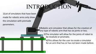
- 3. INTRODUCTION 1)Lot of simulators that have been made for robotic arms only show the simulation with premade parameters. 2)Robotic arm simulator that allows for the creation of any type of robotic arm that has six joints or less. 3)The simulator will allow for the joints of robot to be revolute or prismatic. 4)This allows for the user to create a simulator for an arm that has or has not been made before.
- 4. Technical Background The Toolbox has always provided many functions that are useful for the study and simulation of classical arm-type robotics, for example such things as kinematics, dynamics, and trajectory generation. The Toolbox also provides homogeneous transformations and unit-quaternions which are necessary to represent 3- dimensional positions and orientation of robot. The inverse kinematics (IK) problem for a robot manipulator is to find the values of the joint angles given in the position and orientation of the end-effector relative to the base. There are many solutions to solve the inverse kinematics problem, such as geometric, algebraic, and numerical hit and trial, iterative, FABRIC methods
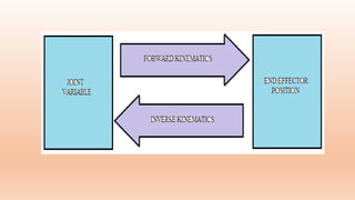
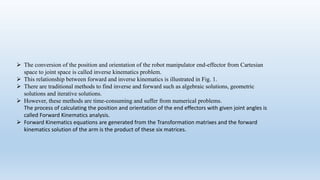
- 6. The conversion of the position and orientation of the robot manipulator end-effector from Cartesian space to joint space is called inverse kinematics problem. This relationship between forward and inverse kinematics is illustrated in Fig. 1. There are traditional methods to find inverse and forward such as algebraic solutions, geometric solutions and iterative solutions. However, these methods are time-consuming and suffer from numerical problems. The process of calculating the position and orientation of the end effectors with given joint angles is called Forward Kinematics analysis. Forward Kinematics equations are generated from the Transformation matrixes and the forward kinematics solution of the arm is the product of these six matrices.
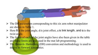
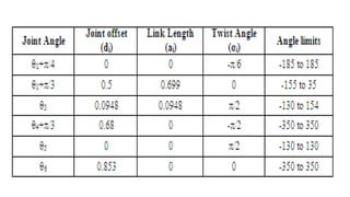
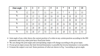
- 7. The DH parameters corresponding to this six arm robot manipulator are shown in Table 1. Here θi is the joint angle, di is joint offset, ai is link length, and αi is the twist angle. The limits of each of the joint angles have also been given in the table and these limits are also used in the mat lab programming. The Denavit- Hartenberg (DH) convention and methodology is used to derive its forward kinematics.
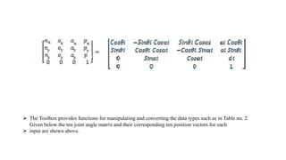
- 9. The Toolbox provides functions for manipulating and converting the data types such as in Table no. 2. Given below the ten joint angle matrix and their corresponding ten position vectors for each input are shown above.
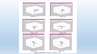
- 10. Joint angle of any robot shows the current position of a robot at any certain position according to the DH parameter and every robot joint have fixed joint limits. We can change the joint angle and corresponding output will change according to the given input. If your given input crosses the limit forward kinematics is possible but inverse kinematics is not possible. It means the output is not real. Some positions of robot are shown in Fig. 3 according to given angle.
- 13. Advantages of the Toolbox 1) The code is quite mature and provides a point of comparison for other implementations of the same algorithms. 2) The routines are generally written in a straightforward manner which allows for easy understanding, perhaps at the expense of computational efficiency. If you feel strongly about computational efficiency then you can always rewrite the function to be more efficient, compile the M-file using the Mat lab compiler, or create a MEX version. 3) Since source code is available there is a benefit for understanding and teaching.
- 14. FUTURE SCOPE Robotics tool box in mat lab is not only limited to forward and inverse kinematics of robot by which we can make controller of robot, can calculate link length and link weight, link momentum, link velocity, maximum limits of robot etc. the data come from robotics tool box you can validate in different tools of mat lab like artificial neural network (ANN), articulated neuro fuzzy interference system(ANFIS) etc.
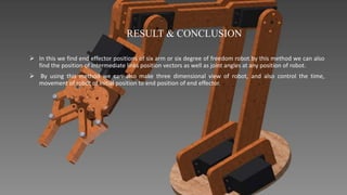
- 15. RESULT & CONCLUSION In this we find end effector positions of six arm or six degree of freedom robot.by this method we can also find the position of intermediate links position vectors as well as joint angles at any position of robot. By using this method we can also make three dimensional view of robot, and also control the time, movement of robot of initial position to end position of end effector.
- 16. REFERENCES Serdar Kucuk and Zafer Bingul Forward and Inverse Kinematics December 2006. Joan Q Gan, Eimei Oyama, Eric M Rosales & Huoheng hu a complete analytical solution to the inverse kinematics of the pioneer 2r robotic am Cambridge journals 7 may 2004. LORENZO SCIAVICCO & BRUNO SCILIANO a solution algorithm to the inverse kinematics problem for redundant manipulator IEEE Journal of Robotics and Automation,Vol. 4 no.4 august 1998. Li – Chun Tommy Wang & Chi Cheng Chen a combined optimization method for solving the inverse kinematics problem for mechanical manipulator IEEE Transaction on Robotics and Automation Vol. 7 No. 4 august 1991. Ziauddin ahmad & Allon Guez On the solution of inverse kinematics problem IEEE 1990. http://www.petercorke.com/robot Robotics toolbox for Mat lab Release 9.0 B Purmus, H. Temurtas & A. Gan An inverse kinematics solution using practical swarm optimization 6th International Advanced Technologies Symposium (IATS’11), 16-18 May 2011, Elazığ, Turkey. Ali T hasan & M.A.A.Al Assadi Performance prediction network for serial manipulator inverse kinematics solution passing through singular configuration Advanced Robotics System International 2010. Adrew A. Goldenberg, B. Benhabib, & Robert G. Fenton a Complete Generalized Solution to the Inverse Kinematics of Robots IEEE JOURNAL OF ROBOTICS AND AUTOMATION, VOL. RA-1, NO. 1, march 1985. Himanshu Chaudhary and Rajendra Prasad Intelegent Inverse kinematics control of scorbot- ER plus robot manipulator International Journal of Advances in Engineering & Technology, Nov 2011. Mustafa Jabbar Hayawi analytical inverse kinematics algorithm Of A 5-DOF robot arm Journal of education of college no.4 vol.1 march./2011.