4.8.compressors
•
2 likes•523 views

The document discusses performance assessment of compressors through field testing. It describes methods to measure free air delivery, isothermal power, volumetric efficiency and specific power requirement. The nozzle method and pump up method are explained to measure free air delivery. Calculations are provided as examples to determine isothermal efficiency, specific power consumption and compare actual performance to design values to assess energy efficiency.
Report
Share
4.8.compressors
- 1. 8. ENERGY PERFORMANCE ASSESSMENT OF COMPRESSORS 8.1 Introduction The compressed air system is not only an energy intensive utility but also one of the least energy efficient. Over a period of time, both performance of compressors and compressed air system reduces drastically. The causes are many such as poor maintenance, wear and tear etc. All these lead to additional compressors installations leading to more inefficiencies. A periodic performance assessment is essential to minimize the cost of compressed air. 8.2 Purpose of the Performance Test To find out: • Actual Free Air Delivery (FAD) of the compressor • Isothermal power required • Volumetric efficiency • Specific power requirement The actual performance of the plant is to be compared with design / standard values for assessing the plant energy efficiency. 8.3 Performance Terms and Definitions Compression ratio : Absolute discharge pressure of last stage Absolute intake pressure Isothermal Power : It is the least power required to compress the air assuming isothermal conditions. Isothermal Efficiency : The ratio of Isothermal power to shaft power Volumetric efficiency : The ratio of Free air delivered to compressor swept volume Specific power requirement: The ratio of power consumption (in kW ) to the volume delivered at ambient conditions. 8.4 Field Testing 8.4.1 Measurement of Free Air Delivery (FAD) by Nozzle method Principle: If specially shaped nozzle discharge air to the atmosphere from a receiver getting its supply from a compressor, sonic flow conditions sets in at the nozzle throat Bureau of Energy Efficiency 107
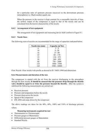
- 2. 8. Energy Performance Assessment of Compressors for a particular ratio of upstream pressure (receiver) to the downstream pressure (atmospheric) i.e. Mach number equals one. When the pressure in the receiver is kept constant for a reasonable intervals of time, the airflow output of the compressor is equal to that of the nozzle and can be calculated from the known characteristic of the nozzle. 8.4.2 Arrangement of test equipment The arrangement of test equipment and measuring device shall confirm to Figure 8.1. 8.4.3 Nozzle Sizes The following sizes of nozzles are recommended for the range of capacities indicated below: Nozzle size (mm) Capacity (m3 /hr) 6 10 16 22 33 50 80 125 165 3 – 9 9 –30 27 –90 60 – 170 130 – 375 300 – 450 750 – 2000 1800 – 5500 3500 - 10000 Flow Nozzle: Flow nozzle with profile as desired in IS 10431:1994 and dimensions 8.4.4 Measurements and duration of the test. The compressor is started with the air from the receiver discharging to the atmosphere through the flow nozzle. It should be ensured that the pressure drop through the throttle valve should be equal to or twice the pressure beyond the throttle. After the system is stabilized the following measurements are carried out: • Receiver pressure • Pressure and temperature before the nozzle • Pressure drop across the nozzle • Speed of the compressor • kW, kWh and amps drawn by the compressor The above readings are taken for the 40%, 60%, 100% and 110% of discharge pressure values. Measuring instruments required for test • Thermometers or Thermocouple • Pressure gauges or Manometers • Differential pressure gauges or Manometers • Standard Nozzle Bureau of Energy Efficiency 108
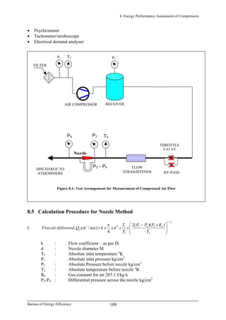
- 3. 8. Energy Performance Assessment of Compressors Bureau of Energy Efficiency 109 • Psychrometer • Tachometer/stroboscope T1P1 Figure 8.1: Test Arrangement for Measurement of Compressed Air Flow FILTER RECEIVER P2 T3 P3 – P4 FLOW STRAIGHTENER BY-PASS THROTTLE VALVE Nozzle P4 P3 AIR COMPRESSOR DISCHARGE TO ATMOSPHERE • Electrical demand analyser 8.5 Calculation Procedure for Nozzle Method I. 2/1 3 343 1 12 ))((2 4 sec)/(, ⎟⎟ ⎠ ⎞ ⎜⎜ ⎝ ⎛ − = T RxPPP x P T xdxxkmQdeliveredairFree as f π k : Flow coefficient – as per IS d : Nozzle diameter M T1 : Absolute inlet temperature o K P1 : Absolute inlet pressure kg/cm2 P3 : Absolute Pressure before nozzle kg/cm2 T3 : Absolute temperature before nozzle o K Ra : Gas constant for air 287.1 J/kg k P3-P4 : Differential pressure across the nozzle kg/cm2
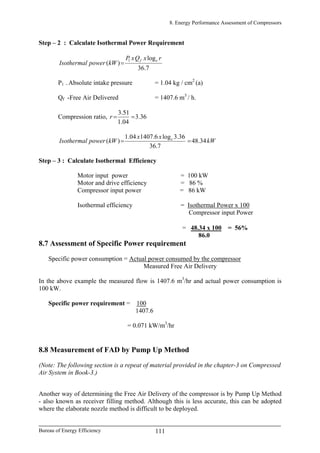
- 4. 8. Energy Performance Assessment of Compressors II. Isothermal Efficiency = Isothermal power / Input power 7.36 log )( 1 rxQxP kWpowerIsothermal ef = P1 = Absolute intake pressure kg/ cm2 Qf = Free air delivered m3 /hr. r = Pressure ratio P2/P1 III. hrmdeliveredairFree kWnconsumptioPower pressureedischratedatnconsumptiopowerSpecific /, , arg 3 = IV. 100 min/ min/ 3 3 x minntdisplacemeCompressor mindeliveredairFree efficiencyVolumetric = nxxSxLxDxntdisplacemeCompressor χ π 2 4 = D = Cylinder bore, metre L = Cylinder stroke, metre S = Compressor speed rpm χ = 1 for single acting and 2 for double acting cylinders n = No. of cylinders 8.6 Example Calculation of Isothermal Efficiency for a Reciprocating Air Compressor. Step – 1 : Calculate Volumetric Flow Rate k : Flow coefficient (Assumed as 1) d : Nozzle diameter : 0.08 metre P2 : Receiver Pressure - 3.5 kg / cm2 (a) P1 : Inlet Pressure - 1.04 kg / cm2 (a) T1 : Inlet air temperature 30o C or 303o K P3 : Pressure before nozzle – 1.08 kg / cm2 T3 : Temperature before the nozzle 40o C or 313o K P3 – P4 : Pressure drop across the nozzle = 0.036 kg / cm2 Ra : Gas constant : 287 Joules / kg K 2/1 3 343 1 12 ))((2 4 sec)/(, ⎟⎟ ⎠ ⎞ ⎜⎜ ⎝ ⎛ − = T RxPPP x P T xdxxkmQdeliveredairFree as f π 2/1 2 313 28708.1036.02 04.1 303 )08.0( 4 1sec)/(, ⎟ ⎠ ⎞ ⎜ ⎝ ⎛ = xxx xxxxmQdeliveredairFree s f π = 0.391 m3 /sec = 1407.6 m3 / h. Bureau of Energy Efficiency 110
- 5. 8. Energy Performance Assessment of Compressors Step – 2 : Calculate Isothermal Power Requirement 7.36 log )( 1 rxQxP kWpowerIsothermal ef = P1 - Absolute intake pressure = 1.04 kg / cm2 (a) Qf -Free Air Delivered = 1407.6 m3 / h. Compression ratio, 36.3 04.1 51.3 ==r kW xx kWpowerIsothermal e 34.48 7.36 36.3log6.140704.1 )( == Step – 3 : Calculate Isothermal Efficiency Motor input power = 100 kW Motor and drive efficiency = 86 % Compressor input power = 86 kW Isothermal efficiency = Isothermal Power x 100 Compressor input Power = 48.34 x 100 = 56% 86.0 8.7 Assessment of Specific Power requirement Specific power consumption = Actual power consumed by the compressor Measured Free Air Delivery In the above example the measured flow is 1407.6 m3 /hr and actual power consumption is 100 kW. Specific power requirement = 100 1407.6 = 0.071 kW/m3 /hr 8.8 Measurement of FAD by Pump Up Method (Note: The following section is a repeat of material provided in the chapter-3 on Compressed Air System in Book-3.) Another way of determining the Free Air Delivery of the compressor is by Pump Up Method - also known as receiver filling method. Although this is less accurate, this can be adopted where the elaborate nozzle method is difficult to be deployed. Bureau of Energy Efficiency 111
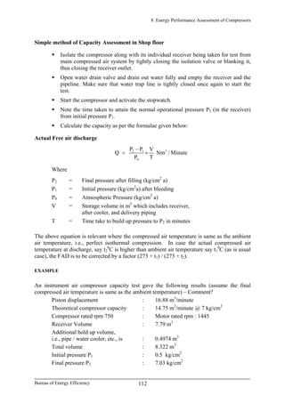
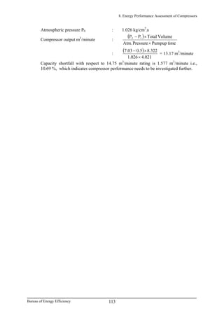
- 6. 8. Energy Performance Assessment of Compressors Simple method of Capacity Assessment in Shop floor Isolate the compressor along with its individual receiver being taken for test from main compressed air system by tightly closing the isolation valve or blanking it, thus closing the receiver outlet. Open water drain valve and drain out water fully and empty the receiver and the pipeline. Make sure that water trap line is tightly closed once again to start the test. Start the compressor and activate the stopwatch. Note the time taken to attain the normal operational pressure P2 (in the receiver) from initial pressure P1. Calculate the capacity as per the formulae given below: Actual Free air discharge 32 1 0 P P V Q Nm / Minute P T − = × Where P2 = Final pressure after filling (kg/cm2 a) P1 = Initial pressure (kg/cm2 a) after bleeding P0 = Atmospheric Pressure (kg/cm2 a) V = Storage volume in m3 which includes receiver, after cooler, and delivery piping T = Time take to build up pressure to P2 in minutes The above equation is relevant where the compressed air temperature is same as the ambient air temperature, i.e., perfect isothermal compression. In case the actual compressed air temperature at discharge, say t2 0 C is higher than ambient air temperature say t1 0 C (as is usual case), the FAD is to be corrected by a factor (273 + t1) / (273 + t2). EXAMPLE An instrument air compressor capacity test gave the following results (assume the final compressed air temperature is same as the ambient temperature) – Comment? Piston displacement : 16.88 m3 /minute Theoretical compressor capacity : 14.75 m3 /minute @ 7 kg/cm2 Compressor rated rpm 750 : Motor rated rpm : 1445 Receiver Volume : 7.79 m3 Additional hold up volume, i.e., pipe / water cooler, etc., is : 0.4974 m3 Total volume : 8.322 m3 Initial pressure P1 : 0.5 kg/cm2 Final pressure P2 : 7.03 kg/cm2 Bureau of Energy Efficiency 112
- 7. 8. Energy Performance Assessment of Compressors Atmospheric pressure P0 : 1.026 kg/cm2 ,a Compressor output m3 /minute : ( ) timePumpupPressureAtm. VolumeTotalPP 12 × ×− : ( ) 4.021.0261 8.3225.003.7 × ×− = 13.17 m3 /minute Capacity shortfall with respect to 14.75 m3 /minute rating is 1.577 m3 /minute i.e., 10.69 %, which indicates compressor performance needs to be investigated further. Bureau of Energy Efficiency 113
- 8. 8. Energy Performance Assessment of Compressors QUESTIONS 1) What is meant by Free Air Delivery? 2) Describe the method of estimating flow by nozzle method. 3) Describe the method of estimating flow by pump up method. 4) Define the term isothermal efficiency and explain its significance. 5) Define the term volumetric efficiency and explain its significance. 6) How is specific power requirement calculated? REFERENCES 1. IS 10431:1994: Measurement of airflow of compressors and exhausters by nozzles. 2. IS 5456:1985 code of practice for testing of positive displacement type air compressors and exhausters 3. Compressor performance – Aerodynamics for the user by M Theodore Gresh- Butterworth Heinemann. Bureau of Energy Efficiency 114