Location via proxy:   [ UP ]  
[Report a bug]   [Manage cookies]                
SlideShare a Scribd company logo
UNIT-2
Design of shaft , Keys and Couplings
 A shaft is a rotating machine element which is used to transmit power from one place to another. with help of
couplings or gears.
 The shafts are usually cylindrical, but may be square or cross-shaped in section. They are solid in cross-section but
sometimes hollow shafts are also used.
Material Used for Shafts
The material used for shafts should have the following properties :
1. It should have high strength.
2. It should have good machinability.
3. It should have low notch sensitivity factor.
4. It should have good heat treatment properties.
5. It should have high wear resistant properties.
The material used for ordinary shafts is carbon steel of grades 40 C 8, 45 C 8, 50 C 4 and 50 C 12.
The mechanical properties of these grades of carbon steel are given in the following table.
Design of shaft
Types of Shafts
The following two types of shafts are important from the subject point of view :
1. Transmission shafts. These shafts transmit power between the source and the machines absorbing power. The counter
shafts, line shafts, over head shafts and all factory shafts are transmission shafts. Since these shafts carry machine parts
such as pulleys, gears etc., therefore they are subjected to bending in addition to twisting.
2. Machine shafts. These shafts form an integral part of the machine itself. The crank shaft is an example of machine shaft.
Stresses in Shafts
The following stresses are induced in the shafts :
1. Shear stresses due to the transmission of torque (i.e. due to torsional load).
2. Bending stresses (tensile or compressive) due to the forces acting upon machine elements like gears, pulleys etc. as well
as due to the weight of the shaft itself.
3. Stresses due to combined torsional and bending loads.
Shafts Subjected to Twisting Moment Only = Torsional shear stress induced at the outer surface of the
shaft or maximum shear stress,
r = Radius of the shaft,
T = Torque or twisting moment,
J = Second moment of area of the section about its polar axis or
polar moment of inertia,
C = Modulus of rigidity for the shaft material,
l = Length of the shaft, and
 = Angle of twist in radians on a length l.
Torque Solid shaft
Torque hollow shaft
polar moment of inertia Solid shaft
polar moment of inertia hollow shaft
power
A line shaft rotating at 200 r.p.m. is to transmit 20 kW. The shaft may be assumed to be made of mild steel with an allowable
shear stress of 42 MPa. Determine the diameter of the shaft, neglecting the bending moment on the shaft.
A solid shaft is transmitting 1 MW at 240 r.p.m. Determine the diameter of the shaft if the maximum torque transmitted
exceeds the mean torque by 20%. Take the maximum allowable shear stress as 60 MPa.
Find the diameter of a solid steel shaft to transmit 20 kW at 200 r.p.m. The ultimate shear stress for the steel may be taken as
360 MPa and a factor of safety as 8.If a hollow shaft is to be used in place of the solid shaft, find the inside and outside
diameter when the ratio of inside to outside diameters is 0.5.
Shafts Subjected to Bending Moment Only
When the shaft is subjected to a bending moment only, then the maximum stress (tensile or compressive) is given by the
bending equation.
Solid shaft
hollow shaft
Shafts Subjected to Combined Twisting Moment and Bending Moment
When the shaft is subjected to combined twisting moment and bending moment, then the shaft must be designed on the
basis of the two moments simultaneously.
equivalent twisting moment
Te=
and
maximum normal stress in the shaft
Me
and
equivalent bending moment
A solid circular shaft is subjected to a bending moment of 3000 N-m and a torque of 10 000 N-m. The shaft is made of 45 C 8
steel having ultimate tensile stress of 700 MPa and a ultimate shear stress of 500 MPa. Assuming a factor of safety as 6,
determine the diameter of the shaft.
Design of machine elements -unit2.pptx

More Related Content

Design of machine elements -unit2.pptx

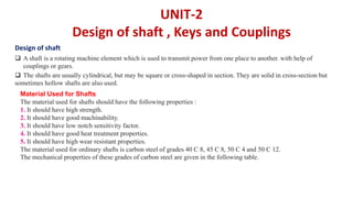
  • 1. UNIT-2 Design of shaft , Keys and Couplings  A shaft is a rotating machine element which is used to transmit power from one place to another. with help of couplings or gears.  The shafts are usually cylindrical, but may be square or cross-shaped in section. They are solid in cross-section but sometimes hollow shafts are also used. Material Used for Shafts The material used for shafts should have the following properties : 1. It should have high strength. 2. It should have good machinability. 3. It should have low notch sensitivity factor. 4. It should have good heat treatment properties. 5. It should have high wear resistant properties. The material used for ordinary shafts is carbon steel of grades 40 C 8, 45 C 8, 50 C 4 and 50 C 12. The mechanical properties of these grades of carbon steel are given in the following table. Design of shaft
  • 2. Types of Shafts The following two types of shafts are important from the subject point of view : 1. Transmission shafts. These shafts transmit power between the source and the machines absorbing power. The counter shafts, line shafts, over head shafts and all factory shafts are transmission shafts. Since these shafts carry machine parts such as pulleys, gears etc., therefore they are subjected to bending in addition to twisting. 2. Machine shafts. These shafts form an integral part of the machine itself. The crank shaft is an example of machine shaft. Stresses in Shafts The following stresses are induced in the shafts : 1. Shear stresses due to the transmission of torque (i.e. due to torsional load). 2. Bending stresses (tensile or compressive) due to the forces acting upon machine elements like gears, pulleys etc. as well as due to the weight of the shaft itself. 3. Stresses due to combined torsional and bending loads. Shafts Subjected to Twisting Moment Only = Torsional shear stress induced at the outer surface of the shaft or maximum shear stress, r = Radius of the shaft, T = Torque or twisting moment, J = Second moment of area of the section about its polar axis or polar moment of inertia, C = Modulus of rigidity for the shaft material, l = Length of the shaft, and  = Angle of twist in radians on a length l.
  • 3. Torque Solid shaft Torque hollow shaft polar moment of inertia Solid shaft polar moment of inertia hollow shaft power
  • 4. A line shaft rotating at 200 r.p.m. is to transmit 20 kW. The shaft may be assumed to be made of mild steel with an allowable shear stress of 42 MPa. Determine the diameter of the shaft, neglecting the bending moment on the shaft.
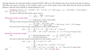
  • 5. A solid shaft is transmitting 1 MW at 240 r.p.m. Determine the diameter of the shaft if the maximum torque transmitted exceeds the mean torque by 20%. Take the maximum allowable shear stress as 60 MPa.
  • 6. Find the diameter of a solid steel shaft to transmit 20 kW at 200 r.p.m. The ultimate shear stress for the steel may be taken as 360 MPa and a factor of safety as 8.If a hollow shaft is to be used in place of the solid shaft, find the inside and outside diameter when the ratio of inside to outside diameters is 0.5.
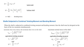
  • 7. Shafts Subjected to Bending Moment Only When the shaft is subjected to a bending moment only, then the maximum stress (tensile or compressive) is given by the bending equation.
  • 8. Solid shaft hollow shaft Shafts Subjected to Combined Twisting Moment and Bending Moment When the shaft is subjected to combined twisting moment and bending moment, then the shaft must be designed on the basis of the two moments simultaneously. equivalent twisting moment Te= and maximum normal stress in the shaft Me and equivalent bending moment
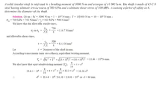
  • 9. A solid circular shaft is subjected to a bending moment of 3000 N-m and a torque of 10 000 N-m. The shaft is made of 45 C 8 steel having ultimate tensile stress of 700 MPa and a ultimate shear stress of 500 MPa. Assuming a factor of safety as 6, determine the diameter of the shaft.