


FEA Comparison in ARAMIS and ARGUS
- 1. Optical Metrology 2009 FEA Comparison in ARAMIS and ARGUS Harald Friebe May 25th 2009
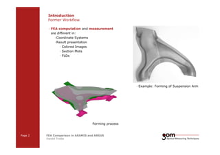
- 2. Introduction Former Workflow — FEA computation and measurement are different in: —Coordinate Systems —Result presentation — Colored Images — Section Plots — FLDs Forming process Page 2 FEA Comparison in ARAMIS and ARGUS Harald Friebe 2-Frame 2-Frame Setup / Frame 1 Setup / Frame 2 — Example: Forming of Suspension Arm 3-Frame Setup / Frame 1 3-Frame Setup / Frame 2 3-Frame Setup / Frame 3
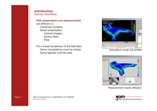
- 3. Introduction Former Workflow — FEA computation and measurement are different in: —Coordinate Systems —Result presentation — Colored Images — Section Plots — FLDs — For a visual comparison of full field data —Same visualizations must be chosen —Same legends must be used Page 3 FEA Comparison in ARAMIS and ARGUS Harald Friebe 2-Frame 2-Frame Setup / Frame 1 Setup / Frame 2 Simulation result (LS-DYNA) Measurement result (ARGUS) 3-Frame Setup / Frame 1 3-Frame Setup / Frame 2 3-Frame Setup / Frame 3
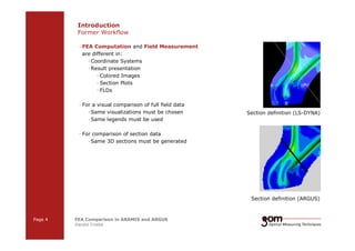
- 4. Introduction Former Workflow — FEA Computation and Field Measurement are different in: —Coordinate Systems —Result presentation — Colored Images — Section Plots — FLDs — For a visual comparison of full field data —Same visualizations must be chosen —Same legends must be used — For comparison of section data —Same 3D sections must be generated Page 4 FEA Comparison in ARAMIS and ARGUS Harald Friebe 2-Frame 2-Frame Setup / Frame 1 Setup / Frame 2 Section definition (LS-DYNA) Section definition (ARGUS) 3-Frame Setup / Frame 1 3-Frame Setup / Frame 2 3-Frame Setup / Frame 3
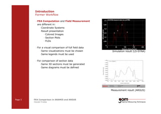
- 5. Introduction Former Workflow — FEA Computation and Field Measurement are different in: —Coordinate Systems —Result presentation — Colored Images — Section Plots — FLDs — For a visual comparison of full field data —Same visualizations must be chosen —Same legends must be used — For comparison of section data —Same 3D sections must be generated —Same diagrams must be defined Page 5 FEA Comparison in ARAMIS and ARGUS Harald Friebe 2-Frame 2-Frame Setup / Frame 1 Setup / Frame 2 Simulation result (LS-DYNA) Measurement result (ARGUS) 3-Frame Setup / Frame 1 3-Frame Setup / Frame 2 3-Frame Setup / Frame 3
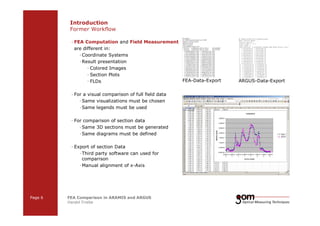
- 6. Introduction Former Workflow — FEA Computation and Field Measurement are different in: —Coordinate Systems —Result presentation — Colored Images — Section Plots — FLDs — For a visual comparison of full field data —Same visualizations must be chosen —Same legends must be used — For comparison of section data —Same 3D sections must be generated —Same diagrams must be defined — Export of section Data — Third party software can used for comparison —Manual alignment of x-Axis Page 6 FEA Comparison in ARAMIS and ARGUS Harald Friebe 2-Frame 2-Frame Setup / Frame 1 Setup / Frame 2 FEA-Data-Export ARGUS-Data-Export 3-Frame Setup / Frame 1 3-Frame Setup / Frame 2 3-Frame Setup / Frame 3
- 7. Introduction Former Workflow — Summary —No automatism — Time consuming —Only comparison of — Local areas (Sections and images) — Rough values (color images) Page 7 FEA Comparison in ARAMIS and ARGUS Harald Friebe 2-Frame 2-Frame Setup / Frame 1 Setup / Frame 2 3-Frame Setup / Frame 1 3-Frame Setup / Frame 2 3-Frame Setup / Frame 3
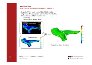
- 8. Introduction FEA Comparison Module in ARAMIS/ARGUS — Import of FEA results in ARAMIS/ARGUS in V6.2 — Alignment of measurement coordinate system to FEA — Calculation of full field deviation for —Geometry —Strain values (Major, Minor, …) Simulation Measurement Page 8 FEA Comparison in ARAMIS and ARGUS Harald Friebe 2-Frame 2-Frame Setup / Frame 1 Setup / Frame 2 Major true strain deviation 3-Frame Setup / Frame 1 3-Frame Setup / Frame 2 3-Frame Setup / Frame 3
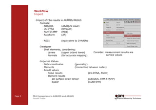
- 9. Workflow Import — Import of FEA results in ARAMIS/ARGUS — Formats: — ABAQUS (ABAQUS input) — LS-DYNA (DYNAIN) — PAM-STAMP (M01) — AutoForm (AF) — ASCII (equivalent to DYNAIN) —Datatypes — Shell elements, considering: — Layers (upper or/and lower) — Normals (for accurate mapping) — Imported Values Consider: measurement results are surface values — Node coordinates (geometry) — Elements (connection between nodes) — Result values — Nodal results (LS-DYNA, ASCII) — Element results — 2D surface strain tensor (ABAQUS, PAM-STAMP) — Scalar (AutoForm) Page 9 FEA Comparison in ARAMIS and ARGUS Harald Friebe 2-Frame 2-Frame Setup / Frame 1 Setup / Frame 2 3-Frame Setup / Frame 1 3-Frame Setup / Frame 2 3-Frame Setup / Frame 3
- 10. Workflow Alignment — For comparison Measurement and FEA must have the same coordinate system — Transformation Measurement coordinate system FEA coordinate system Page 10 FEA Comparison in ARAMIS and ARGUS Harald Friebe 2-Frame 2-Frame Setup / Frame 1 Setup / Frame 2 Without alignment 3-Frame Setup / Frame 1 3-Frame Setup / Frame 2 3-Frame Setup / Frame 3 by —Manual Transformation Functions — 321-Transformation — Translation, Rotation —Best fit alignment — Pre-orientation — Best fit by selected areas After pre-orientation After best fit by complete surface
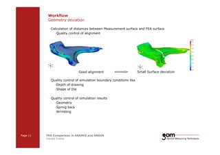
- 11. Workflow Geometry deviation — Calculation of distances between Measurement surface and FEA surface —Quality control of alignment Good alignment — Quality control of simulation boundary conditions like —Depth of drawing —Shape of Die — Quality control of simulation results —Geometry —Spring back —Wrinkling Page 11 FEA Comparison in ARAMIS and ARGUS Harald Friebe 2-Frame 2-Frame Setup / Frame 1 Setup / Frame 2 Small Surface deviation 3-Frame Setup / Frame 1 3-Frame Setup / Frame 2 3-Frame Setup / Frame 3
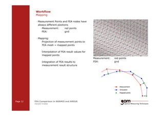
- 12. Workflow Mapping — Measurement Points and FEA nodes have always different positions —Measurement: red points — FEA: gird — Mapping: — Projection of measurement points to FEA mesh = mapped points — Interpolation of FEA result values for mapped points — Integration of FEA results to measurement result structure Page 12 FEA Comparison in ARAMIS and ARGUS Harald Friebe 2-Frame 2-Frame Setup / Frame 1 Setup / Frame 2 Measurement: red points FEA: gird 3-Frame Setup / Frame 1 3-Frame Setup / Frame 2 3-Frame Setup / Frame 3
- 13. Workflow Deviation calculation — Calculation of deviations for all points, e.g.: Major Strain deviation = Major (measurement point) – Major (mapped point) Measurement Mapped Simulation Page 13 FEA Comparison in ARAMIS and ARGUS Harald Friebe 2-Frame 2-Frame Setup / Frame 1 Setup / Frame 2 Major strain deviation 3-Frame Setup / Frame 1 3-Frame Setup / Frame 2 3-Frame Setup / Frame 3
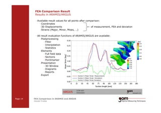
- 14. FEA Comparison Result Results in ARAMIS/ARGUS — Available result values for all points after comparison: —Coordinates —3D Displacements of measurement, FEA and deviation —Strains (Major, Minor, Mises, …) — All result evaluation functions of ARAMIS/ARGUS are available: — Postprocessing — Filter — Interpolation — Statistics —Elements — Full field data — Sections — Pointmarker — Presentation — 3D Window — Diagrams — Reports —Export Page 14 FEA Comparison in ARAMIS and ARGUS Harald Friebe 2-Frame 2-Frame Setup / Frame 1 Setup / Frame 2 3-Frame Setup / Frame 1 3-Frame Setup / Frame 2 3-Frame Setup / Frame 3
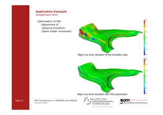
- 15. Application Example Suspension Arm — Optimization of FEA —Adjustment of clamping simulation (blank holder movement) Page 15 FEA Comparison in ARAMIS and ARGUS Harald Friebe 2-Frame 2-Frame Setup / Frame 1 Setup / Frame 2 Major true strain deviation of first simulation step Major true strain deviation after FEA optimization 3-Frame Setup / Frame 1 3-Frame Setup / Frame 2 3-Frame Setup / Frame 3
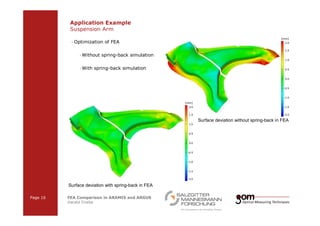
- 16. Application Example Suspension Arm — Optimization of FEA —Without spring-back simulation —With spring-back simulation Surface deviation with spring-back in FEA Page 16 FEA Comparison in ARAMIS and ARGUS Harald Friebe 2-Frame 2-Frame Setup / Frame 1 Setup / Frame 2 Surface deviation without spring-back in FEA 3-Frame Setup / Frame 1 3-Frame Setup / Frame 2 3-Frame Setup / Frame 3
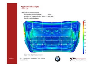
- 17. Application Example Trunk Lid — ARGUS XL measurement —Unformed point distance: 1mm —Amount of measurement point: 1.300.000 — Points made by Laser Major true strain measurement Page 17 FEA Comparison in ARAMIS and ARGUS Harald Friebe 2-Frame 2-Frame Setup / Frame 1 Setup / Frame 2 3-Frame Setup / Frame 1 3-Frame Setup / Frame 2 3-Frame Setup / Frame 3
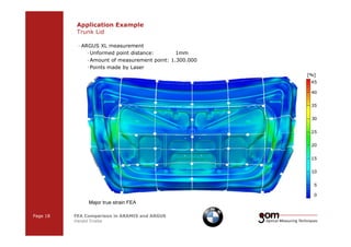
- 18. Application Example Trunk Lid — ARGUS XL measurement —Unformed point distance: 1mm —Amount of measurement point: 1.300.000 — Points made by Laser Major true strain FEA Page 18 FEA Comparison in ARAMIS and ARGUS Harald Friebe 2-Frame 2-Frame Setup / Frame 1 Setup / Frame 2 3-Frame Setup / Frame 1 3-Frame Setup / Frame 2 3-Frame Setup / Frame 3
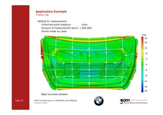
- 19. Application Example Trunk Lid — ARGUS XL measurement —Unformed point distance: 1mm —Amount of measurement point: 1.300.000 — Points made by Laser Major true strain deviation Page 19 FEA Comparison in ARAMIS and ARGUS Harald Friebe 2-Frame 2-Frame Setup / Frame 1 Setup / Frame 2 3-Frame Setup / Frame 1 3-Frame Setup / Frame 2 3-Frame Setup / Frame 3
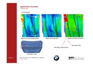
- 20. Application Example Trunk Lid — Local details Major true strain measurement Major true strain FEA Major true strain deviation Simulation mesh Page 20 FEA Comparison in ARAMIS and ARGUS Harald Friebe 2-Frame 2-Frame Setup / Frame 1 Setup / Frame 2 Boundary FEA Boundary measurement 3-Frame Setup / Frame 1 3-Frame Setup / Frame 2 3-Frame Setup / Frame 3
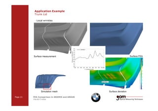
- 21. Application Example Trunk Lid — Local wrinkles Surface measurement Surface FEA Page 21 FEA Comparison in ARAMIS and ARGUS Harald Friebe 2-Frame 2-Frame Setup / Frame 1 Setup / Frame 2 3-Frame Setup / Frame 1 3-Frame Setup / Frame 2 3-Frame Setup / Frame 3 Simulation mesh Surface deviation
- 22. Application Example Trunk Lid — Local detail: Missing seam in FEA Simulation mesh Surface measurement Surface FEA Seam No Seam Major true strain measurement Major true strain FEA Major true strain deviation Page 22 FEA Comparison in ARAMIS and ARGUS Harald Friebe 2-Frame 2-Frame Setup / Frame 1 Setup / Frame 2 3-Frame Setup / Frame 1 3-Frame Setup / Frame 2 3-Frame Setup / Frame 3
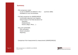
- 23. Summary — FEA-comparison modul — Is part of ARAMIS and ARGUS in V6.2 (summer 2009) —Available for Linux and Windows — Full field comparison for ARAMIS/ARGUS —Comfortable alignment and mapping —Determination of full field deviations for — Geometry — Displacements — Strains (Major, Minor, …) — Easy and comfortable — FEA verification —Result evaluation —Reporting — Comparison from measurement to measurement (ARAMIS/ARGUS) Page 23 FEA Comparison in ARAMIS and ARGUS Harald Friebe 2-Frame 2-Frame Setup / Frame 1 Setup / Frame 2 3-Frame Setup / Frame 1 3-Frame Setup / Frame 2 3-Frame Setup / Frame 3
- 24. Thank you for your attention info@gom.com www.gom.com