Location via proxy:   [ UP ]  
[Report a bug]   [Manage cookies]                
SlideShare a Scribd company logo
CE8394-FLUID MECHANICS
AND MACHINERY
Regulation 2017
SEM:3rd
1Dr V.KANDAVEL Asp/Mech. SSMIET, DGL-2
Unit-IV
UNIT IV - PUMPS
• Impact of jets
• Euler’s equation
• Theory of roto-dynamic machines
– Various efficiencies
– Velocity components at entry and exit of the rotor
– Velocity triangles
• Centrifugal pumps
– Working principle
– Work done by the impeller
– Performance curves
• Reciprocating pump
– Working principle
• Rotary pumps
– Classification.
Dr V.KANDAVEL Asp/Mech. SSMIET, DGL-2 2
Impact of jets
• When a jet of water strikes a surface, its velocity (and hence
its momentum) is changed. The force exerted by the surface
on the jet is then obtained by applying Newton's Second
Law, i.e. the force normal to the surface is equal to the rate
of change of momentum, or change of momentum per
second, normal to the surface.
Fluid Mechanics Unit-4  (vk-ssm)
Euler’s equation
• the Euler equations are a set of quasilinear hyperbolic equations
governing adiabatic and in viscid flow. They are named after Leonhard
Euler.
• Euler's pump equation, plays a central role in turbomachinery as it
connects the specific work Y and the geometry and velocities in the
impeller. The equation is based on the concepts of conservation of
angular momentum and conservation of energy.
Fluid Mechanics Unit-4  (vk-ssm)
• The term ‘rotodynamic machine’ is used to describe machines
which cause a change of total head of the fluid flowing through
them by virtue of the dynamic effect they have upon the fluid.
Machines exist which change the head of the working fluid without
employing a dynamic effect, for example reciprocating pumps.
Fluid Mechanics Unit-4  (vk-ssm)
Contd.,
• a mechanism for converting the energy of a
moving liquid or gas into the energy of a rotating
shaft (for example, a hydroturbine), or vice versa
(for example, a ventilator). A single-
stage machine consists of a rotor and devices for
the intake and discharge of fluid.
Fluid Mechanics Unit-4  (vk-ssm)
Various efficiencies:
Fluid Mechanics Unit-4  (vk-ssm)
Velocity components at entry and exit of the rotor
Fluid Mechanics Unit-4  (vk-ssm)
Velocity triangles
Fluid Mechanics Unit-4  (vk-ssm)
Rotary pumps
• A positive displacement pump. For each revolution of the pump, a fixed
volume of fluid is moved regardless of the resistance against which the
pump is pushing. It is self-priming, and gives practically constant delivered
capacity regardless of the pressure. The rotary pump consists of a fixed
casing containing gears, cams, screws, plungers or similar elements
actuated by rotation of the drive shaft. A number of pump types are
included in this classification, among which are the gear pump, the screw
pump, and the rotary vane pump.
• Rotary pumps are useful for pumping oil and other liquids of high viscosity.
In the engine room, rotary pumps are used for handling lube oil and fuel oil
and are suitable for handling liquids over a wide range of viscosities. Rotary
pumps are designed with very small clearances between rotating parts and
stationary parts to minimize leakage (slippage) from the discharge side back
to the suction side. Rotary pumps are designed to operate at relatively low
speeds to maintain these clearances. The operation at higher speeds causes
erosion and excessive wear which result in increased clearances with a
subsequent decrease in pumping capacity. Classification of the rotary
pumps is generally based on the types of rotating element.
Rotary pumps Classification.
• Gear pump
• Rotary vane pumps
• Screw pump
• - Gear pump – The simple gear pump has two spur gears that mesh together
and revolve in opposite directions. One is the driving gear, and the other is
the driven gear. Clearances between the gear teeth (outside diameter of the
gear) and the casing and between the end face and the casing are only a few
thousandths of an inch. As the gears turn, they unmesh and liquid flows into
the pockets that are vacated by the meshing gear teeth. This creates the
suction that draws the liquid into the pump. The liquid is then carried along
in the pockets formed by the gear teeth and the casing. On the discharge
side, the liquid is displaced by the meshing of the gears and forced out
through the discharge side of the pump.
• Rotary vane pumps – The rotary vane
pump has a cylindrically-bored housing with
a suction inlet on one side and a discharge
outlet on the other side. A rotor (smaller in
diameter than the cylinder) is driven about
an axis that is placed above the center line
of the cylinder to provide minimum
clearance between the rotor and cylinder at
the top and maximum clearance at the
bottom. The rotor carries vanes (which
move in and out as the rotor rotates) to
maintain sealed spaces between the rotor
and the cylinder wall. The vanes trap liquid
on the suction side and carry it to the
discharge side, where contraction of the
space expels liquid through the discharge
line. The vanes slide on slots in the rotor.
Vane pumps are used for lube oil service
and transfer, tank stripping, bilge, and in
general, for handling lighter viscous liquids.
• Screw pump – There are several different types of screw pumps.
The differences between the various types are the number of
intermeshing screws and the screw pitch. Screw pumps are used
aboard ship to pump fuel and lube oil and to supply pressure to the
hydraulic system. In the double-screw pump, one rotor is driven by
the drive shaft and the other by a set of timing gears. In the triple-
screw pump, a central rotor meshes with two idler rotors. In the
screw pump, liquid is trapped and forced through the pump by the
action of rotating screws. As the rotor turns, the liquid flows in
between the threads at the outer end of each pair of screws. The
threads carry the liquid along within the housing to the center of
the pump where it is discharged. Most screw pumps are now
equipped with mechanical seals. If the mechanical seal fails, the
stuffing box has the capability of accepting two rings of
conventional packing for emergency use.
UNIT-IV
Formulae Summary
Fluid Mechanics Unit-4  (vk-ssm)
THANK YOU

More Related Content

Fluid Mechanics Unit-4 (vk-ssm)

  • 1. CE8394-FLUID MECHANICS AND MACHINERY Regulation 2017 SEM:3rd 1Dr V.KANDAVEL Asp/Mech. SSMIET, DGL-2 Unit-IV
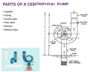
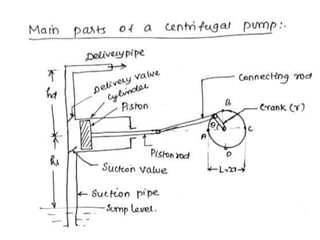
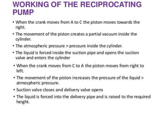
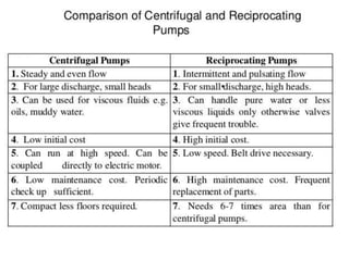
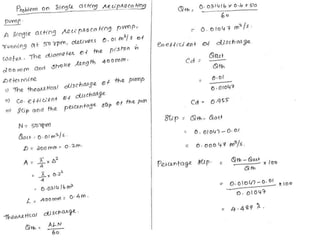
  • 2. UNIT IV - PUMPS • Impact of jets • Euler’s equation • Theory of roto-dynamic machines – Various efficiencies – Velocity components at entry and exit of the rotor – Velocity triangles • Centrifugal pumps – Working principle – Work done by the impeller – Performance curves • Reciprocating pump – Working principle • Rotary pumps – Classification. Dr V.KANDAVEL Asp/Mech. SSMIET, DGL-2 2
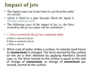
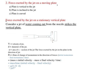
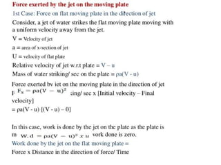
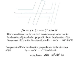
  • 3. Impact of jets • When a jet of water strikes a surface, its velocity (and hence its momentum) is changed. The force exerted by the surface on the jet is then obtained by applying Newton's Second Law, i.e. the force normal to the surface is equal to the rate of change of momentum, or change of momentum per second, normal to the surface.
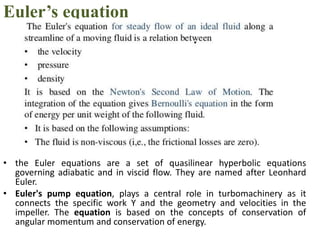
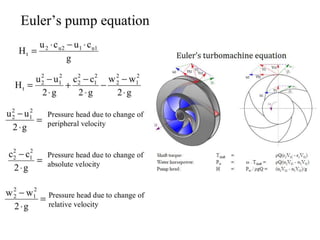
  • 7. Euler’s equation • the Euler equations are a set of quasilinear hyperbolic equations governing adiabatic and in viscid flow. They are named after Leonhard Euler. • Euler's pump equation, plays a central role in turbomachinery as it connects the specific work Y and the geometry and velocities in the impeller. The equation is based on the concepts of conservation of angular momentum and conservation of energy.
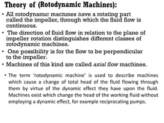
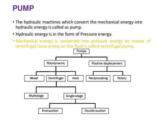
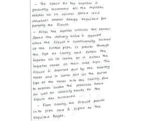
  • 9. • The term ‘rotodynamic machine’ is used to describe machines which cause a change of total head of the fluid flowing through them by virtue of the dynamic effect they have upon the fluid. Machines exist which change the head of the working fluid without employing a dynamic effect, for example reciprocating pumps.
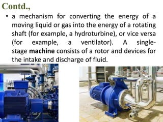
  • 11. Contd., • a mechanism for converting the energy of a moving liquid or gas into the energy of a rotating shaft (for example, a hydroturbine), or vice versa (for example, a ventilator). A single- stage machine consists of a rotor and devices for the intake and discharge of fluid.
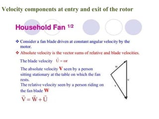
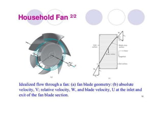
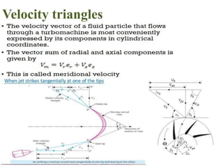
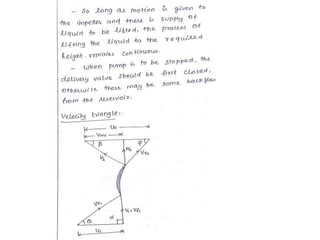
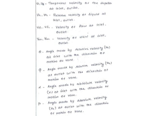
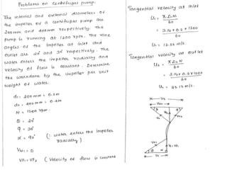
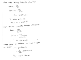
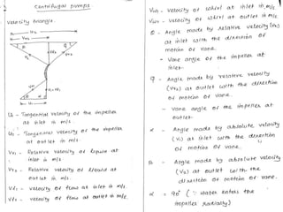
  • 15. Velocity components at entry and exit of the rotor
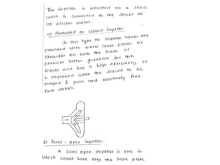
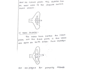
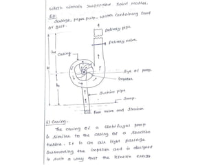
  • 60. Rotary pumps • A positive displacement pump. For each revolution of the pump, a fixed volume of fluid is moved regardless of the resistance against which the pump is pushing. It is self-priming, and gives practically constant delivered capacity regardless of the pressure. The rotary pump consists of a fixed casing containing gears, cams, screws, plungers or similar elements actuated by rotation of the drive shaft. A number of pump types are included in this classification, among which are the gear pump, the screw pump, and the rotary vane pump. • Rotary pumps are useful for pumping oil and other liquids of high viscosity. In the engine room, rotary pumps are used for handling lube oil and fuel oil and are suitable for handling liquids over a wide range of viscosities. Rotary pumps are designed with very small clearances between rotating parts and stationary parts to minimize leakage (slippage) from the discharge side back to the suction side. Rotary pumps are designed to operate at relatively low speeds to maintain these clearances. The operation at higher speeds causes erosion and excessive wear which result in increased clearances with a subsequent decrease in pumping capacity. Classification of the rotary pumps is generally based on the types of rotating element.
  • 61. Rotary pumps Classification. • Gear pump • Rotary vane pumps • Screw pump
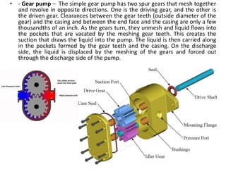
  • 62. • - Gear pump – The simple gear pump has two spur gears that mesh together and revolve in opposite directions. One is the driving gear, and the other is the driven gear. Clearances between the gear teeth (outside diameter of the gear) and the casing and between the end face and the casing are only a few thousandths of an inch. As the gears turn, they unmesh and liquid flows into the pockets that are vacated by the meshing gear teeth. This creates the suction that draws the liquid into the pump. The liquid is then carried along in the pockets formed by the gear teeth and the casing. On the discharge side, the liquid is displaced by the meshing of the gears and forced out through the discharge side of the pump.
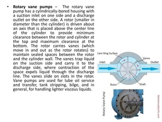
  • 63. • Rotary vane pumps – The rotary vane pump has a cylindrically-bored housing with a suction inlet on one side and a discharge outlet on the other side. A rotor (smaller in diameter than the cylinder) is driven about an axis that is placed above the center line of the cylinder to provide minimum clearance between the rotor and cylinder at the top and maximum clearance at the bottom. The rotor carries vanes (which move in and out as the rotor rotates) to maintain sealed spaces between the rotor and the cylinder wall. The vanes trap liquid on the suction side and carry it to the discharge side, where contraction of the space expels liquid through the discharge line. The vanes slide on slots in the rotor. Vane pumps are used for lube oil service and transfer, tank stripping, bilge, and in general, for handling lighter viscous liquids.
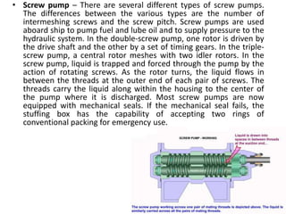
  • 64. • Screw pump – There are several different types of screw pumps. The differences between the various types are the number of intermeshing screws and the screw pitch. Screw pumps are used aboard ship to pump fuel and lube oil and to supply pressure to the hydraulic system. In the double-screw pump, one rotor is driven by the drive shaft and the other by a set of timing gears. In the triple- screw pump, a central rotor meshes with two idler rotors. In the screw pump, liquid is trapped and forced through the pump by the action of rotating screws. As the rotor turns, the liquid flows in between the threads at the outer end of each pair of screws. The threads carry the liquid along within the housing to the center of the pump where it is discharged. Most screw pumps are now equipped with mechanical seals. If the mechanical seal fails, the stuffing box has the capability of accepting two rings of conventional packing for emergency use.