
FM 753
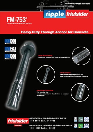
- 1. Heavy Duty Metal Anchors HIGH RESISTANCE Achieved through the cold forging process I S O 9 0 0 1 C e r t . n ° 1 0 8 5 ISO 14001 C er t . n° 0050A CERTIFICATION OF QUALITY MANAGEMENT SYSTEM CERTIFICATION OF ENVIRONMENTAL MANAGEMENT SYSTEMsince 1966 FM-753® ETA OPTION 7: FOR UNCRACKED CONCRETE Heavy Duty Through Anchor for Concrete UNIFORM EXPANSION The special clip ensures an uniform distribution of pressure in the hole ANTI-SLIDING The shape of the expander clip guarantees a high fastening capacity
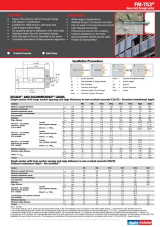
- 2. -Stainless steel A4 (AISI 316) -Assembled Versions Available • FM 753 (White Zinc Plated) • FM 753 INOX (Stainless Steel) • FM 753 Nautilus (Anti-Corrosion Coating) Applications • Hand Rails, Guard Rails • Facade Brackets & Clamps • Pipe Supports, Channels • Warehousing Racks • Elevators, Escalators • Columns & Beams Fixing • Consoles • Cable Trays, Conduits • Gates & Grills • Mechanical Equipments • Stadium Seat Fastening • Steel & Wood Constructions FM-753® Heavy duty through anchor White zinc plated Assembled -Stainless steel A4 clip -Assembled (1) Anchors with reduced embedment depths. (2) Sizes not covered by CE certification. *50 for Stainless steel A4. White zinc plated Code Stainless steel A4 Code NAUTILUS Code d x L mm Thread length mm tfix mm df mm sw Box q.ty Outer box 75320b06045(1)(2) 75320c06045(1) M6x45 20 3 7 10 200 2000 75320b06065 75320006065(2) 75320c06065 M6x65 40 15 7 10 100 1000 75320b06085 75320006085(2) 75320c06085 M6x85 60 35 7 10 100 1000 75320b06100 75320c06100 M6x100 60 50 7 10 50 500 75320b08050(1)(2) 75320008050(1)(2) 75320c08050(1) M8x50 23 5 9 13 100 1000 75320b08065 75320008065 75320c08065 M8x65 38 7 9 13 100 800 75320b08075 75320008075 75320c08075 M8x75 48 15 9 13 100 800 75320b08090 75320008090 75320c08090 M8x90 63 30 9 13 100 500 75320b08115 75320008115 75320c08115 M8x115 83 55 9 13 100 500 75320b08135 75320008135 75320c08135 M8x135 88 75 9 13 100* 500 75320b08165 75320008165 75320c08165 M8x165 88 105 9 13 50 250 75320b10060(1)(2) 75320010060(1)(2) 75320c10060(1) M10x60 28 5 12 17 50 500 75320b10075 75320010075 75320c10075 M10x75 43 5 12 17 50 500 75320b10090 75320010090 75320c10090 M10x90 55 20 12 17 50 400 75320b10100 75320c10100 M10x100 60 30 12 17 50 400 75320b10120 75320010120 75320c10120 M10x120 85 50 12 17 50 250 75320b10145 75320c10145 M10x145 85 75 12 17 50 250 75320b10170 75320c10170 M10x170 85 100 12 17 50 200 75320b10210(2) M10x210 85 140 12 17 25 200 75320b12080(1)(2) 75320012080(1)(2) 75320c12080(1) M12x80 40 7 14 19 50 300 75320b12100 75320012100 75320c12100 M12x100 58 10 14 19 50 250 75320b12110 75320012110 75320c12110 M12x110 68 20 14 19 50 250 75320b12135 75320012135 75320c12135 M12x135 93 45 14 19 25 200 75320b12160 75320012160 75320c12160 M12x160 93 70 14 19 25 150 75320b12185 75320012185 75320c12185 M12x185 93 100 14 19 25 150 75320b12200(2) M12x200 93 115 14 19 20 120 75320b12220(2) M12x220 93 135 14 19 20 120 75320b12240(2) M12x240 93 155 14 19 20 120 75320b12255(2) M12x255 93 170 14 19 20 100 75320b12285(2) M12x285 93 200 14 19 20 100 75320b12300(2) M12x300 93 215 14 19 20 100 75320b12325(2) M12x325 93 240 14 19 20 75 75320b12355(2) M12x335 93 270 14 19 20 75 75320b14100 M14x100 50 3 16 22 25 150 75320b14110 M14x110 60 10 16 22 25 150 75320b14130 M14x130 65 30 16 22 25 150 75320b14150 M14x150 90 50 16 22 25 100 75320b14170 M14x170 90 70 16 22 25 100 75320b14200 M14x200 90 100 16 22 25 100 75320b16110(1)(2) 75320016110(1)(2) 75320c16110(1) M16x110 53 15 18 24 20 100 75320b16125 75320016125 75320c16125 M16x125 68 10 18 24 20 100 75320b16145 75320016145 75320c16145 M16x145 88 30 18 24 20 100 75320b16175 75320016175 75320c16175 M16x175 88 60 18 24 20 80 75320b16215 75320c16215 M16x215 88 100 18 24 15 60 75320b16230(2) M16x230 88 115 18 24 10 50 75320b16250(2) M16x250 88 135 18 24 10 50 75320b16270(2) M16x270 88 155 18 24 10 50 75320b16285(2) M16x285 88 170 18 24 10 50 75320b16320(2) M16x320 88 205 18 24 10 50 75320b20170(2) 75320c20170 M20x170 60 30 22 30 10 50 75320b20215(2) 75320c20215 M20x215 60 75 22 30 10 50 75320b24160s(1)(2) M24x160 60 10 26 36 10 75320b24180s(2) M24x180 60 10 26 36 10 75320b24200s(2) M24x200 80 30 26 36 10 75320b24220s(2) M24x220 100 50 26 36 10 75320b24260s(2) M24x260 100 90 26 36 10 75320b24310s(2) M24x310 100 140 26 36 10 -Special anti-corrosion coating -with matte finish - 1000 hours in salt spray test 1000 h ►►FM-753® NAUTILUS ►►FM-753® - INOX A4 - ►►FM-753® INOX: STAINLESS STEEL UNIFORM EXPANSION The special clip ensures an uniform distribution of pressure in the hole HIGH RESISTANCE Achieved through the cold forging process ANTI-SLIDING The shape of the expander clip guarantees a high fastening capacity Option 7 Heavy duty through anchor for Un-cracked concrete
- 3. Insallation Proceedure FM-753® Heavy duty through anchor Anchor M6 M8 M10 M12 M14 M16 M20 M24 Minimum support thickness hmin mm 100 100 100 120 140 170 200 240 Minimum hole depth h1 mm 50 60 70 85 95 115 130 165 Nominal embedment depth hnom mm 41 48 59 71 80 96 115 145 Minimum depth of anchorage hef mm 35 40 50 60 70 85 95 120 Hole diameter d0 mm 6 8 10 12 14 16 20 24 Spacing Scr,N mm 105 120 150 180 210 255 290 360 Edge distance Ccr,N mm 53 60 75 90 105 130 145 180 FM-753® - CE certified white zinc plated ETA 01/0014 Tensile non-cracked concrete Nrd kN 3.4 5.0 6.7 13.3 16.7 23.4 23.5(3) 32.0(3) N kN 2.4 3.6 4.8 9.5 11.9 16.7 17.0(3) 23.0(3) Shear C >= 10xhef Vrd kN 4.1 6.0 9.8 12.3 21.4 28.1 37.0(3) 53.0(3) V kN 2.9 4.3 7.0 8.8 15.3 20.1 26.5(3) 38.0(3) FM-753® - CE certified stainless steel A4 ETA 01/0009 Tensile non-cracked concrete Nrd kN 2.2(3) 5.0 8.0 15.5 - 23.4 - - N kN 1.6(3) 3.6 5.7 11.1 - 16.7 - - Shear C >= 10xhef Vrd kN 3.5(3) 9.0 14.1 20.7 - 38.5 - - V kN 2.5(3) 6.4 10.1 14.8 - 27.5 - - FM-753® - CE certified NAUTILUS hrg opaque ETA 13/0367 Tensile non-cracked concrete Nrd kN 4.1 8.0 8.0 15.7 - 23.4 26.6 - N kN 2.9 5.7 5.7 11.2 - 16.7 19.0 - Shear C >= 10xhef Vrd kN 4.3 6.2 9.2 13.4 - 28.4 34.3 - V kN 3.1 4.4 6.6 9.6 - 20.3 24.5 - Minimum spacing Smin mm 50 60 75 90 105 130 145 180 Minimum edge distance Cmin mm 50 60 75 90 105 130 145 180 Shear C = Cmin Vrd,cmin kN 1.7 2.5 3.9 5.7 7.8 11.6 15.3 23.2 Vcmin kN 1.2 1.8 2.8 4.1 5.6 8.3 10.9 16.6 Torque Tinst Nm 6 15 25 50 70 100 160 200 DESIGN(1) AND RECOMMENDED(2) LOADS Single anchor with large anchor spacing and edge distances in non-cracked concrete C20/25 - Standard embedment depth Single anchor with large anchor spacing and edge distances in non-cracked concrete C20/25 Reduced embedment depth - Not certified(4) Anchor M6 M8 M10 M12 M16 M24 Minimum support thickness hmin mm 100 100 100 100 130 200 Minimum hole depth h1 mm 45 50 55 70 95 145 Nominal embedment depth hnom mm 36 38 44 56 76 125 Minimum depth of anchorage hef mm 30 30 35 45 65 100 Hole diameter d0 mm 6 8 10 12 16 24 Spacing Scr,N mm 120 120 140 180 260 400 Edge distance Ccr,N mm 90 90 105 135 195 300 FM-753® - CE certified NAUTILUS hrg opaque ETA 13/0367 Tensile non-cracked concrete Nrd kN 3.4 4.1 4.1 8.0 17.6 - N kN 2.4 2.9 2.9 5.7 12.6 - Shear C >= 10xhef Vrd kN 4.3 6.2 9.2 13.4 28.4 - V kN 3.1 4.4 6.6 9.6 20.3 - Tensile/Shear non-cracked concrete Not certified(3) Frd kN 1.8 2.0 3.5 4.9 8.4 11.2 F kN 1.3 1.4 2.5 3.5 6.0 8.0 Minimum spacing Smin mm 45 50 55 70 100 150 Minimum edge distance Cmin mm 45 50 55 70 100 150 Torque Tinst Nm 6 15 25 50 100 200 1kN = 100 kgf (1) The design loads Nrd and Vrd derive from the characteristic loads on the ETA certification and are inclusive of the partial safety factors gm proportional to each diameter (see ETA). (2) The recommended loads N and V derive from the characteristic loads on the ETA certification and are inclusive of the partial safety factors gf =1.4 and gm proportional to each diameter (see ETA). (3) Versions Not Certified: white zinc plated and size M6 of stainless steel A4. The recommended loads N, V or F derive from the mean ultimate loads and are inclusive of the total safety factor g=4 (shear g=3). In the absence of CE markings, the recommended loads derive from tests carried out in the Friulsider laboratory in accordance with the appropriate standards. The load values are only valid if the installation has been carried out correctly. The designing and calculation of the anchorage should be carried out in accordance with annex C, of the ETAG 001, design method A. d = screw diameter df = hole diameter of fixing element do = hole diameter h1 = minimum hole depth hef = minimum depth of anchorage hmin = minimum support thickness hnom = nominal embedment depth L = anchor length sw = wrench tfix = fixture thickness Tinst = torque • Heavy Duty Anchor bolt for through fixings • ETA Option 7 Certification • Certified for 1000 hours in salt spray test • Cold Forged Anchor Body • Six gripping dents for adheshion with hole walls • Stainless Steel Clip with Innovative Design • Hole Diamater & Anchor Diameter is the same • Increased thickness of three expander segments FEATURES • Wide range of Applications • Reliable fixing in Uncracked concrete • Can be used in Corrosive Environments • High Resistance Ductile • Prevents the anchor from rotating • Uniform distribution in the Hole • Same Diameter drill bit can be used • Friction & Keying Effect ADVANTAGES Base Materials Cracked Concrete Solid Stone
- 4. O u r R a n g e o f P r o d u c t s I n d i a TM