


fundamentals of Piping engineering
- 1. Fundamentals of Piping Design Engineering
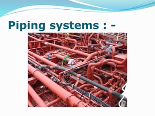
- 3. Piping systems : -
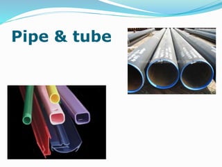
- 4. Pipe & tube
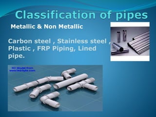
- 5. Metallic & Non Metallic Carbon steel , Stainless steel , Plastic , FRP Piping, Lined pipe.
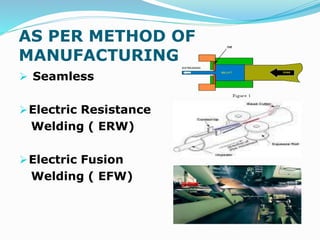
- 6. AS PER METHOD OF MANUFACTURING Seamless Electric Resistance Welding ( ERW) Electric Fusion Welding ( EFW)
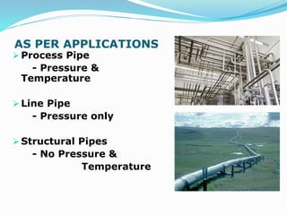
- 7. AS PER APPLICATIONS Process Pipe - Pressure & Temperature Line Pipe - Pressure only Structural Pipes - No Pressure & Temperature
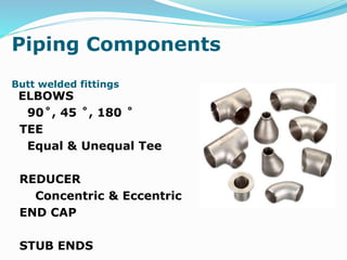
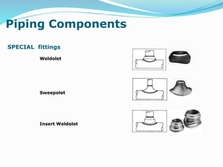
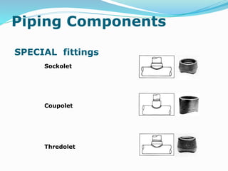
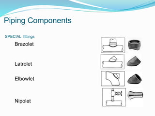
- 8. Piping Components Butt welded fittings ELBOWS 90˚, 45 ˚, 180 ˚ TEE Equal & Unequal Tee REDUCER Concentric & Eccentric END CAP STUB ENDS
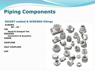
- 9. Piping Components SOCKET welded & SCREWED fittings ELBOWS 90˚, 45 ˚ TEE Equal & Unequal Tee REDUCER Concentric & Eccentric UNION COUPLING HALF COUPLING CAP
- 13. FLOW DIAGRAMS PFD (Process Flow Diagram) PID (Piping & Instrumentation Diagram) UFD (Utility Flow Diagram)
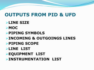
- 14. OUTPUTS FROM PID & UFD LINE SIZE MOC PIPING SYMBOLS INCOMING & OUTGOINGS LINES PIPING SCOPE LINE LIST EQUIPMENT LIST INSTRUMENTATION LIST
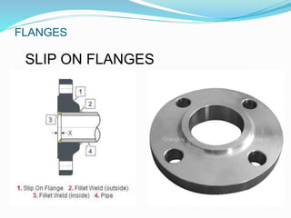
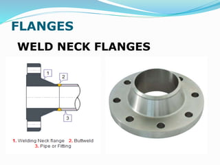
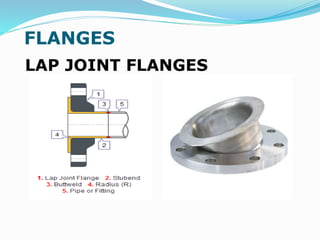
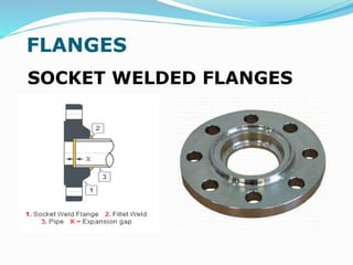
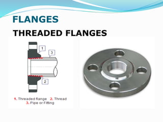
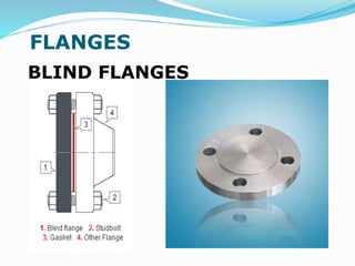
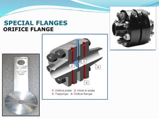
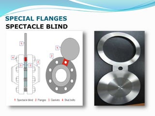
- 15. FLANGES
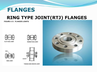
- 21. FLANGES RING TYPE JOINT(RTJ) FLANGES
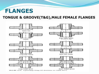
- 22. FLANGES TONGUE & GROOVE(T&G),MALE FEMALE FLANGES
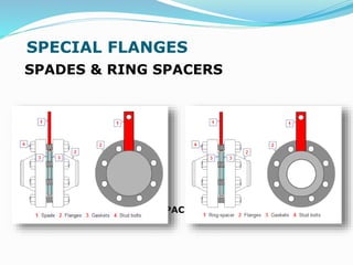
- 26. SPECIAL FLANGES SPADES & RING SPACERS SPADES RING SPACERS
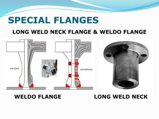
- 27. SPECIAL FLANGES LONG WELD NECK FLANGE & WELDO FLANGE WELDO FLANGE LONG WELD NECK
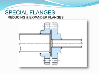
- 28. SPECIAL FLANGES REDUCING & EXPANDER FLANGES
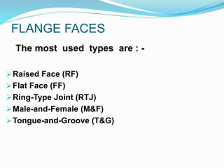
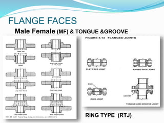
- 29. FLANGE FACES The most used types are : - Raised Face (RF) Flat Face (FF) Ring-Type Joint (RTJ) Male-and-Female (M&F) Tongue-and-Groove (T&G)
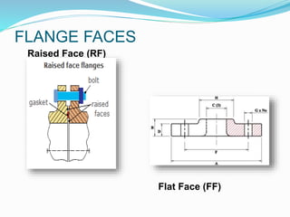
- 30. FLANGE FACES Raised Face (RF) Flat Face (FF)
- 31. FLANGE FACES Male Female (MF) & TONGUE &GROOVE RING TYPE (RTJ)
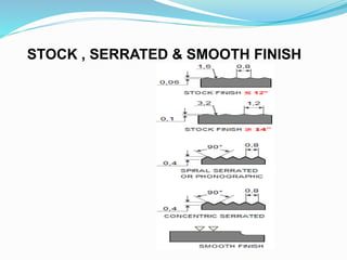
- 32. STOCK , SERRATED & SMOOTH FINISH
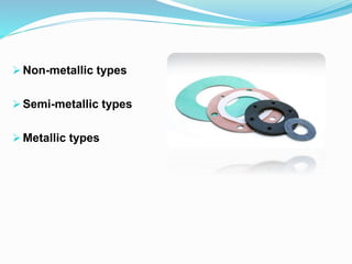
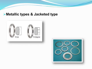
- 37. Metallic types & Jacketed type
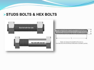
- 38. STUDS BOLTS & HEX BOLTS
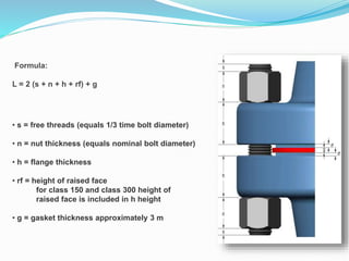
- 39. Formula: L = 2 (s + n + h + rf) + g • s = free threads (equals 1/3 time bolt diameter) • n = nut thickness (equals nominal bolt diameter) • h = flange thickness • rf = height of raised face for class 150 and class 300 height of raised face is included in h height • g = gasket thickness approximately 3 m
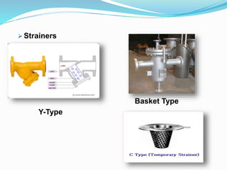
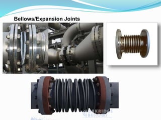
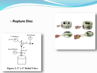
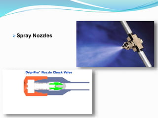
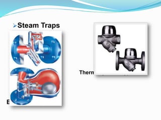
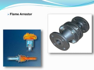
- 40. Strainers Bellows/Expansion Joints Rupture Disc Spray Nozzles Steam Traps Flame Arrestor Vortex Breaker Hose
- 43. Rupture Disc
- 44. Spray Nozzles
- 45. Steam Traps Thermodynamic type Ball float type
- 46. Flame Arrestor
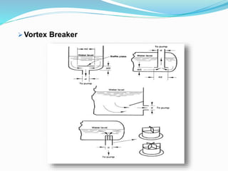
- 47. Vortex Breaker
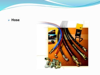
- 48. Hose
- 49. Stress = Force / Cross sectional area Strain = Deformation / Original Length
- 50. = 1/3 X TENSILE STRENGTH. = 2/3 X YIELD STRENGTH .
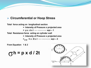
- 51. Circumferential or Hoop Stress Total force acting on longitudinal section = Intensity of Pressure x projected area = p x d x l - - - - - - - - - eqn – 1 Total Resistance force acting on cylinder wall = Intensity of Pressure x projected area = h x 2t x l - - - - - - - - - eqn – 2 From Equation 1 & 2 h = p x d / 2t
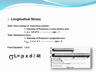
- 52. Longitudinal Stress Total force acting on transverse section = Intensity of Pressure x cross section area = p x π/4 d^2 - - - - - - - - - eqn – 1 Total Resistance force = Intensity of Pressure x projected area = L x π d t - - - - - - - - - eqn – 2 From Equation 1 & 2 L= p x d / 4t
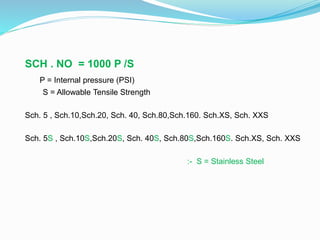
- 53. SCH . NO = 1000 P /S P = Internal pressure (PSI) S = Allowable Tensile Strength Sch. 5 , Sch.10,Sch.20, Sch. 40, Sch.80,Sch.160. Sch.XS, Sch. XXS Sch. 5S , Sch.10S,Sch.20S, Sch. 40S, Sch.80S,Sch.160S. Sch.XS, Sch. XXS :- S = Stainless Steel
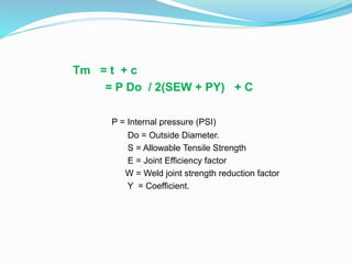
- 54. Tm = t + c = P Do / 2(SEW + PY) + C P = Internal pressure (PSI) Do = Outside Diameter. S = Allowable Tensile Strength E = Joint Efficiency factor W = Weld joint strength reduction factor Y = Coefficient.
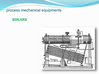
- 55. process mechanical equipments STATIC HORIZONTAL VESSEL VERTICAL VESSEL STOARAGE TANK HEAT EXCHANGER BOILERS DISTILATION COLUMN
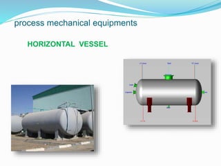
- 56. process mechanical equipments HORIZONTAL VESSEL
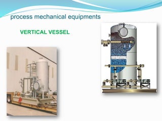
- 57. process mechanical equipments VERTICAL VESSEL
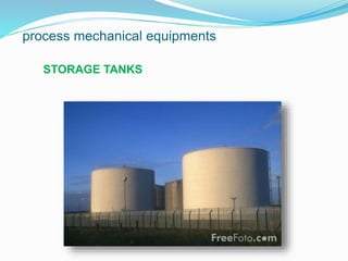
- 58. process mechanical equipments STORAGE TANKS
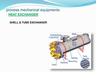
- 59. process mechanical equipments HEAT EXCHANGER SHELL & TUBE EXCHANGER
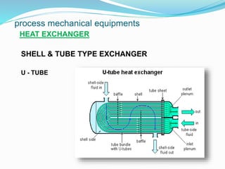
- 60. process mechanical equipments HEAT EXCHANGER SHELL & TUBE TYPE EXCHANGER U - TUBE
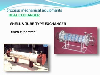
- 61. process mechanical equipments HEAT EXCHANGER SHELL & TUBE TYPE EXCHANGER FIXED TUBE TYPE
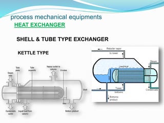
- 62. process mechanical equipments HEAT EXCHANGER SHELL & TUBE TYPE EXCHANGER KETTLE TYPE
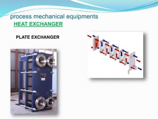
- 63. process mechanical equipments HEAT EXCHANGER PLATE EXCHANGER
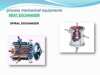
- 64. process mechanical equipments HEAT EXCHANGER SPIRAL EXCHANGER
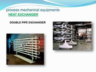
- 65. process mechanical equipments HEAT EXCHANGER DOUBLE PIPE EXCHANGER
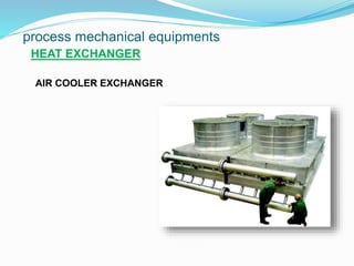
- 66. process mechanical equipments HEAT EXCHANGER AIR COOLER EXCHANGER
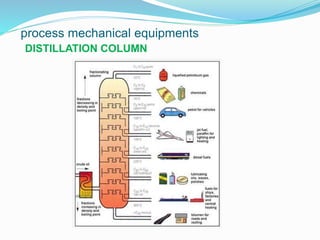
- 68. process mechanical equipments DISTILLATION COLUMN
- 69. Pipe Racks and Sleepers : Sleepers:
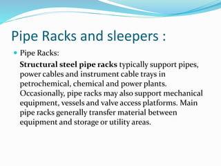
- 70. Pipe Racks and sleepers : Pipe Racks: Structural steel pipe racks typically support pipes, power cables and instrument cable trays in petrochemical, chemical and power plants. Occasionally, pipe racks may also support mechanical equipment, vessels and valve access platforms. Main pipe racks generally transfer material between equipment and storage or utility areas.
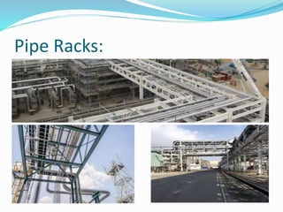
- 71. Pipe Racks:
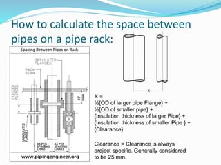
- 73. How to calculate the space between pipes on a pipe rack: X = ½{OD of larger pipe Flange} + ½{OD of smaller pipe} + {Insulation thickness of larger Pipe} + {Insulation thickness of smaller Pipe } + {Clearance} Clearance = Clearance is always project specific. Generally considered to be 25 mm.
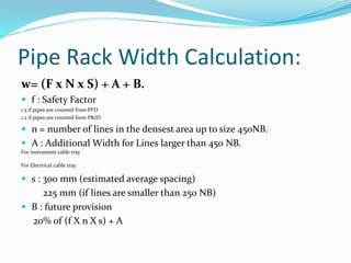
- 74. Pipe Rack Width Calculation: w= (F x N x S) + A + B. f : Safety Factor 1.5 if pipes are counted from PFD. 1.2 if pipes are counted from P&ID. n = number of lines in the densest area up to size 450NB. A : Additional Width for Lines larger than 450 NB. For instrument cable tray For Electrical cable tray. s : 300 mm (estimated average spacing) 225 mm (if lines are smaller than 250 NB) B : future provision 20% of (f X n X s) + A
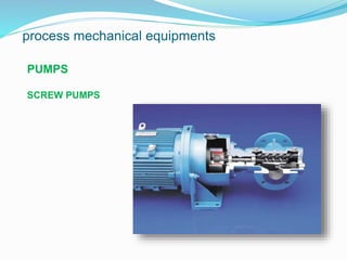
- 75. process mechanical equipments ROTARY PUMPS COMPRESSORS FANS / BLOWERS STEAM TURBINES
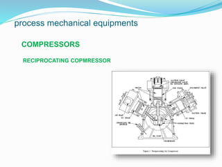
- 79. process mechanical equipments COMPRESSORS RECIPROCATING COPMRESSOR
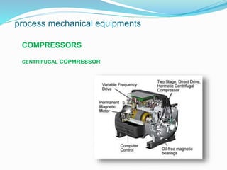
- 80. process mechanical equipments COMPRESSORS CENTRIFUGAL COPMRESSOR
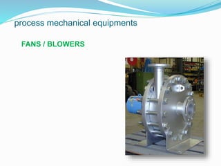
- 81. process mechanical equipments FANS / BLOWERS
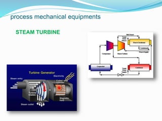
- 82. process mechanical equipments STEAM TURBINE
- 83. Pump Cavitations Simply defined, cavitations is the formation of bubbles or cavities in liquid, developed in areas of relatively low pressure around an impeller. The imploding or collapsing of these bubbles trigger intense shockwaves inside the pump, causing significant damage to the impeller and/or the pump housing. If left untreated, pump cavitations can cause: Failure of pump housing Destruction of impeller Excessive Vibration leading to premature seal and bearing failure Higher than necessary power consumption Decreased flow and/or pressure
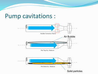
- 84. Pump cavitations : Air Bubble Solid particles
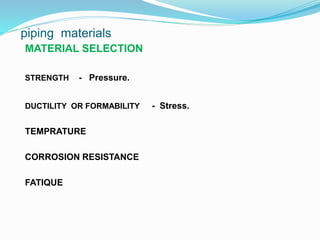
- 85. piping materials MATERIAL SELECTION STRENGTH - Pressure. DUCTILITY OR FORMABILITY - Stress. TEMPRATURE CORROSION RESISTANCE FATIQUE
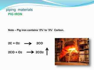
- 86. piping materials PIG IRON Note – Pig iron contains ‘2%’ to ‘3%’ Carbon. 2C + O2 2CO 2CO + O2 2CO2
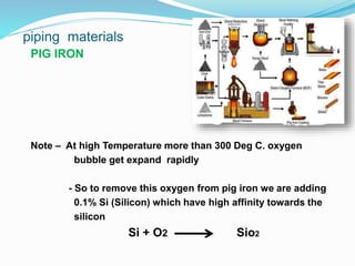
- 87. piping materials PIG IRON Note – At high Temperature more than 300 Deg C. oxygen bubble get expand rapidly - So to remove this oxygen from pig iron we are adding 0.1% Si (Silicon) which have high affinity towards the silicon Si + O2 Sio2
- 88. piping materials CARBON STEEL - Then we will get Deoxidized steel called as “ KILLED STEELS “ - Si(Silicon) is doing Deoxidizing Process. - ASTM A 106 Gr . A - 0.25 C , 0.1 Si. Gr. B - 0.30 C , 0.1 Si. Gr . C - 0.35 C , 0.1 Si.
- 89. piping materials ASTM A – 53 A – Indicate Ferrous material as a main material B – Non Ferrous material. C – Non Metallic material. Note – If Carbon content more than “ 0.35 ” material becomes Brittle - Material contain carbon more than “ 0.35 “ are not weldeble
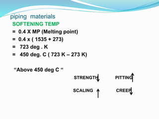
- 90. piping materials SOFTENING TEMP = 0.4 X MP (Melting point) = 0.4 x ( 1535 + 273) = 723 deg . K = 450 deg. C ( 723 K – 273 K) “Above 450 deg C “ STRENGTH PITTING SCALING CREEP
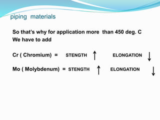
- 91. piping materials So that’s why for application more than 450 deg. C We have to add Cr ( Chromium) = STENGTH ELONGATION Mo ( Molybdenum) = STENGTH ELONGATION
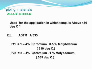
- 92. piping materials ALLOY STEELS Used for the application in which temp. is Above 450 deg C “ Ex. ASTM A 335 P11 = 1 – 4% Chromium , 0.5 % Molybdenum ( 510 deg C.) P22 = 2 – 4% Chromium , 1 % Molybdenum ( 565 deg C.)
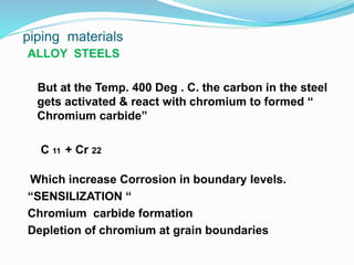
- 93. piping materials ALLOY STEELS But at the Temp. 400 Deg . C. the carbon in the steel gets activated & react with chromium to formed “ Chromium carbide” C 11 + Cr 22 Which increase Corrosion in boundary levels. “SENSILIZATION “ Chromium carbide formation Depletion of chromium at grain boundaries
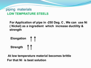
- 94. piping materials LOW TEMPRATURE STEELS For Application of pipe in -250 Deg. C , We can use Ni ( Nickel) as a ingredient which increase ductility & strength Elongation Strength At low temperature material becomes brittle For that Ni is best solution
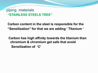
- 95. piping materials “STAINLESS STEELS TREE” Carbon content in the steel is responsible for the “Sensilization” for that we are adding ‘ Titanium ‘ Carbon has high affinity towards the titanium than chromium & chromium get safe that avoid Sensilization of ‘C’
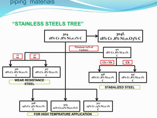
- 96. piping materials “STAINLESS STEELS TREE” 304 18% Cr ,8% Ni,0.1% C 304L 18% Cr ,8% Ni,0.O3% C 317 18% Cr ,8% Ni,0.1% C 316 18% Cr ,8% Ni,0.1% C 321 18% Cr ,8% Ni,0.1% C 347 18% Cr ,8% Ni,0.1% C 348 18% Cr ,8% Ni,0.1% C 2% Mb 4% Mb Titanium (10% of Carbon) Cb + Nb Cb 308 19% Cr ,9% Ni,0.1% C 309 20% Cr,12% Ni,0.1% C 310 25% Cr ,14% Ni,0.1% C WEAR RESISTANCE STEEL STABALIZED STEEL FOR HIGH TEMPRATURE APPLICATION
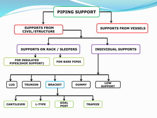
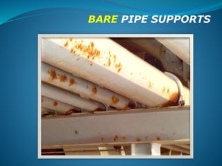
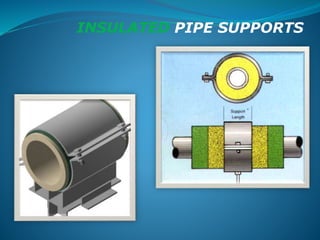
- 98. PIPING SUPPORT SUPPORTS FROM CIVIL/STRUCTURE SUPPORTS FROM VESSELS SUPPORTS ON RACK / SLEEPERS INDIVIDUAL SUPPORTS FOR INSULATED PIPES(SHOE SUPPORT) FOR BARE PIPES LUG TRUNION BRACKET DUMMY LOW SUPPORT CANTILEVER L-TYPE GOAL POST TRAPEZE
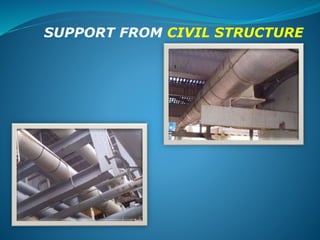
- 99. SUPPORT FROM CIVIL STRUCTURE
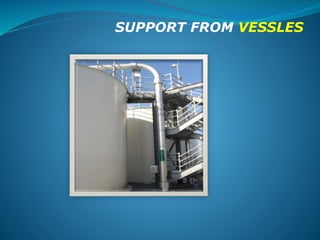
- 100. SUPPORT FROM VESSLES
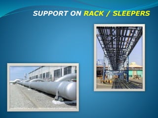
- 101. SUPPORT ON RACK / SLEEPERS
- 102. BARE PIPE SUPPORTS
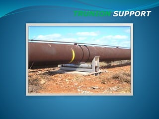
- 104. TRUNION SUPPORT
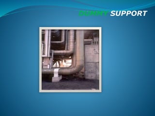
- 105. DUMMY SUPPORT
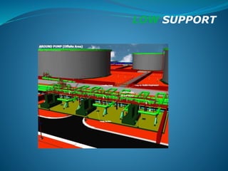
- 106. LOW SUPPORT
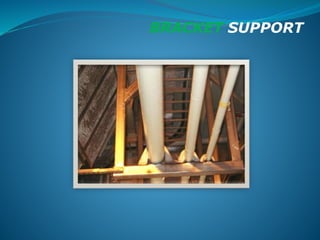
- 107. BRACKET SUPPORT
- 108. BRACKET SUPPORT CANTILEVER , L - TYPE
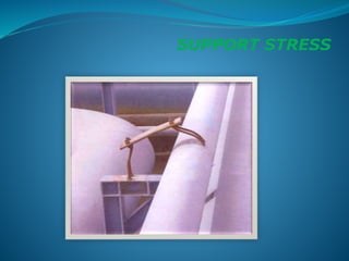
- 110. SUPPORT STRESS
- 111. Question Round Come up with at least five questions each Discuss the Possible answers Note down any questions for the future Answer your own questions by researching.
- 112. The End Presentation by Mobin Varghese Piping engineer Exint Solutions Pvt. Ltd.