


Hydraulic and Pneumatic Actuators
- 1. ME407 MECHATRONICS SUKESH O P Assistant Professor Dept. of Mechanical Engineering JECC 10/16/18 1SUKESH O P/ APME/ME407- MR-2018 SUKESH O P/ APME/ME407- MR-2018
- 2. ME407 MECHATRONICS Course Objectives: To introduce the features of various sensors used in CNC machines and robots To study the fabrication and functioning of MEMS pressure and inertial sensors To enable development of hydraulic/pneumatic circuit and PLC programs for simple applications 10/16/18 2 SUKESH O P/ APME/ME407- MR-2018SUKESH O P/ APME/ME407- MR-2018
- 3. Expected outcome: The students will be able to i. Know the mechanical systems used in mechatronics ii. Integrate mechanical, electronics, control and computer engineering in the design of mechatronics systems ME407 MECHATRONICS 10/16/18 3 SUKESH O P/ APME/ME407- MR-2018SUKESH O P/ APME/ME407- MR-2018
- 4. Expected outcome: The students will be able to i. Know the mechanical systems used in mechatronics ii. Integrate mechanical, electronics, control and computer engineering in the design of mechatronics systems ME407 MECHATRONICS 10/16/18 4 SUKESH O P/ APME/ME407- MR-2018SUKESH O P/ APME/ME407- MR-2018
- 5. SYLLABUS Introduction to Mechatronics, sensors, Actuators, Micro Electro Mechanical Systems (MEMS), Mechatronics in Computer Numerical Control (CNC) machines, Mechatronics in Robotics-Electrical drives, Force and tactile sensors, Image processing techniques, Case studies of Mechatronics systems. 10/16/18 5 SUKESH O P/ APME/ME407- MR-2018SUKESH O P/ APME/ME407- MR-2018
- 6. MODULE-II Actuators: Hydraulic and Pneumatic actuators - Directional control valves, pressure control valves, process control valves. Rotary actuators. Development of simple hydraulic and pneumatic circuits using standard Symbols. 10/16/18 6 SUKESH O P/ APME/ME407- MR-2018SUKESH O P/ APME/ME407- MR-2018
- 7. MODULE-II Actuators: Hydraulic and Pneumatic actuators 10/16/18 7 SUKESH O P/ APME/ME407- MR-2018SUKESH O P/ APME/ME407- MR-2018
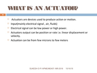
- 8. WHAT IS AN ACTUATOR? Actuators are devices used to produce action or motion. Input(mainly electrical signal , air, fluids) Electrical signal can be low power or high power. Actuators output can be position or rate i.e. linear displacement or velocity. Actuation can be from few microns to few meters 10/16/18 8 SUKESH O P/ APME/ME407- MR-2018SUKESH O P/ APME/ME407- MR-2018
- 9. FLOWDIAGRAMOF AN ACTUATOR 10/16/18 9 SUKESH O P/ APME/ME407- MR-2018SUKESH O P/ APME/ME407- MR-2018
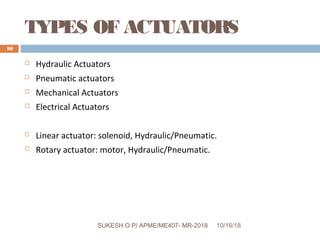
- 10. TYPES OF ACTUATORS Hydraulic Actuators Pneumatic actuators Mechanical Actuators Electrical Actuators Linear actuator: solenoid, Hydraulic/Pneumatic. Rotary actuator: motor, Hydraulic/Pneumatic. 10/16/18 10 SUKESH O P/ APME/ME407- MR-2018SUKESH O P/ APME/ME407- MR-2018
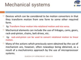
- 11. Devices which can be considered to be motion converters in that they transform motion from one form to some other required form. Eg: Transform linear motion into rotational motion and vice versa. Mechanical elements can include the use of linkages, cams, gears, rack-and-pinion, chains, belt drives, etc. Eg: rack-and-pinion can be used to convert rotational motion to linear motion. Many of the actions which previously were obtained by the use of mechanism are, however, often nowadays being obtained, as a result of a mechatronics approach by the use of microprocessor systems. SUKESH O P/ APME/ME407- MR-2018
- 12. Mechanisms still, however, have a role in mechatronics systems. For example, the mechatronics system in use in an automatic camera for adjusting the aperture for correct exposures involves a mechanism for adjusting the size of diaphragm. Others function: Force amplification – given by levers. Change of speed – given by gears. Transfer of rotation about one axis to rotation about another – timing belt. The term kinematics is used for the study of motion without regard to forces. When we consider just the motions without any consideration of the forces or energy involved then we are carrying out a kinematic analysis of the mechanism. SUKESH O P/ APME/ME407- MR-2018
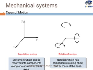
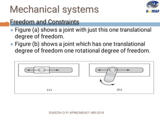
- 13. Translation motion Rotational motion Movement which can be resolved into components along one or more of the 3 Movement which can be resolved into components along one or more of the 3 Rotation which has components rotating about one or more of the axes. Rotation which has components rotating about one or more of the axes.SUKESH O P/ APME/ME407- MR-2018
- 14. SUKESH O P/ APME/ME407- MR-2018
- 15. SUKESH O P/ APME/ME407- MR-2018
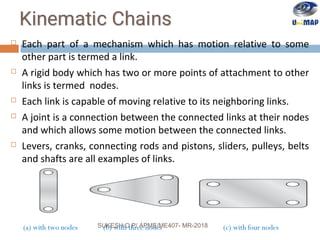
- 16. Each part of a mechanism which has motion relative to some other part is termed a link. A rigid body which has two or more points of attachment to other links is termed nodes. Each link is capable of moving relative to its neighboring links. A joint is a connection between the connected links at their nodes and which allows some motion between the connected links. Levers, cranks, connecting rods and pistons, sliders, pulleys, belts and shafts are all examples of links. (a) with two nodes (c) with four nodes(b) with three nodesSUKESH O P/ APME/ME407- MR-2018
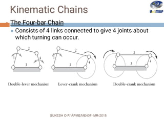
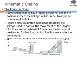
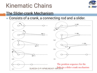
- 17. A sequence of joints and links is known as kinematic chain. For a kinematic chain to transmit motion, one link must be fixed. Movement of one link will then produce predictable relative movements of the others. It is possible to obtain from one kinematic chain a number of different mechanisms by having a different link as the fixed one. The design of many mechanisms are based on two basic forms of kinematic chains, the four-bar chain and the slider-crank chain. The reciprocating motion of a piston is transformed into rotational motion of a crankshaft on bearings mounted in a fixed frame. The reciprocating motion of a piston is transformed into rotational motion of a crankshaft on bearings mounted in a fixed frame. Slider Crankshaft Connecting rod Fixed frame SUKESH O P/ APME/ME407- MR-2018
- 18. Double-lever mechanism Lever-crank mechanism Double-crank mechanism SUKESH O P/ APME/ME407- MR-2018
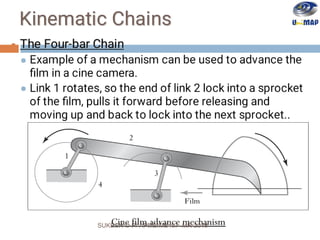
- 19. Cine film advance mechanismSUKESH O P/ APME/ME407- MR-2018
- 20. SUKESH O P/ APME/ME407- MR-2018
- 21. The position sequence for the links in a slider-crank mechanismSUKESH O P/ APME/ME407- MR-2018
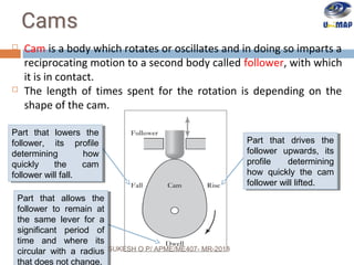
- 22. Cam is a body which rotates or oscillates and in doing so imparts a reciprocating motion to a second body called follower, with which it is in contact. The length of times spent for the rotation is depending on the shape of the cam. Part that lowers the follower, its profile determining how quickly the cam follower will fall. Part that lowers the follower, its profile determining how quickly the cam follower will fall. Part that allows the follower to remain at the same lever for a significant period of time and where its circular with a radius Part that allows the follower to remain at the same lever for a significant period of time and where its circular with a radius that does not change. Part that drives the follower upwards, its profile determining how quickly the cam follower will lifted. Part that drives the follower upwards, its profile determining how quickly the cam follower will lifted. SUKESH O P/ APME/ME407- MR-2018
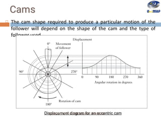
- 23. The cam shape required to produce a particular motion of the follower will depend on the shape of the cam and the type of follower used. Displacement diagram for an eccentric camSUKESH O P/ APME/ME407- MR-2018
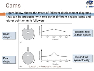
- 24. Figure below shows the types of follower displacement diagrams that can be produced with two other different shaped cams and either point or knife followers. Heart shape Heart shape Pear shape Pear shape (constant rate, uniform speed) (constant rate, uniform speed) (rise and fall symmetrically) (rise and fall symmetrically) SUKESH O P/ APME/ME407- MR-2018
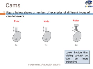
- 25. Figure below shows a number of examples of different types of cam followers. Point RollerKnife Lower friction than sliding contact but can be more expensive Lower friction than sliding contact but can be more expensive SUKESH O P/ APME/ME407- MR-2018
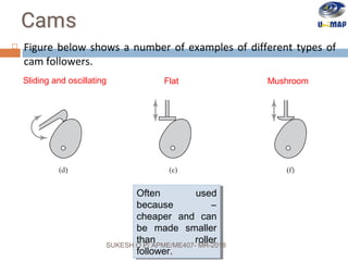
- 26. Figure below shows a number of examples of different types of cam followers. Often used because – cheaper and can be made smaller than roller follower. Often used because – cheaper and can be made smaller than roller follower. Sliding and oscillating Flat Mushroom SUKESH O P/ APME/ME407- MR-2018
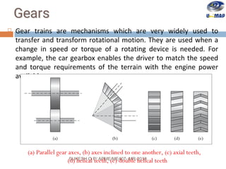
- 27. Gear trains are mechanisms which are very widely used to transfer and transform rotational motion. They are used when a change in speed or torque of a rotating device is needed. For example, the car gearbox enables the driver to match the speed and torque requirements of the terrain with the engine power available. (a) Parallel gear axes, (b) axes inclined to one another, (c) axial teeth, (d) helical teeth, (e) double helical teethSUKESH O P/ APME/ME407- MR-2018
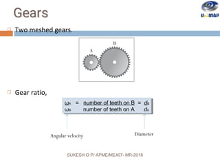
- 28. Two meshed gears. Gear ratio, ωA = number of teeth on B = dB ωB number of teeth on A dA ωA = number of teeth on B = dB ωB number of teeth on A dA Angular velocity Diameter SUKESH O P/ APME/ME407- MR-2018
- 29. G = ωA = ωA ωB ωC ωB ωC G = ωA = ωA ωB ωC ωB ωC x SUKESH O P/ APME/ME407- MR-2018
- 30. Compound gears trains – two wheels are mounted on a common shaft. Ratio of the angular velocities, For the input and output shafts to be in line, we must also have for the radii of the gears. G = ωA = ωA ωB ωC = ωA ωC ωD ωB ωC ωD ωB ωD G = ωA = ωA ωB ωC = ωA ωC ωD ωB ωC ωD ωB ωDxx x rA + rB = rD + rCrA + rB = rD + rCSUKESH O P/ APME/ME407- MR-2018
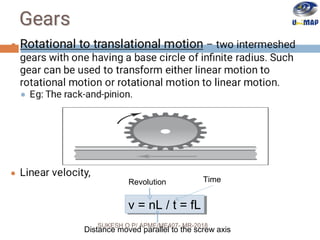
- 31. v = nL / t = fLv = nL / t = fL Time Distance moved parallel to the screw axis Revolution SUKESH O P/ APME/ME407- MR-2018
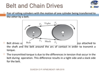
- 32. Pair of rolling cylinders with the motion of one cylinder being transferred to the other by a belt. Belt drives use the friction that develops between the pulleys attached to the shaft and the belt around the arc of contact in order to transmit a torque. The transmitted torque is due to the differences in tension that occur in the belt during operation. This difference results in a tight side and a slack side for the belt. SUKESH O P/ APME/ME407- MR-2018
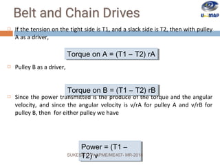
- 33. If the tension on the tight side is T1, and a slack side is T2, then with pulley A as a driver, Pulley B as a driver, Since the power transmitted is the produce of the torque and the angular velocity, and since the angular velocity is v/rA for pulley A and v/rB for pulley B, then for either pulley we have Torque on A = (T1 – T2) rATorque on A = (T1 – T2) rA Power = (T1 – T2) v Power = (T1 – T2) v Torque on B = (T1 – T2) rBTorque on B = (T1 – T2) rB SUKESH O P/ APME/ME407- MR-2018
- 34. As a method of transmitting power between two shafts, belt drives have the advantage that the length of the belt can easily be adjusted to suit a wide range of shaft to shaft distance and the system is automatically protected against overload because slipping occurs if the loading exceeds the maximum tension that can be sustained by frictional forces. If the distance between shafts is large, a belt drive is more suitable than gears, but over small distances gears are to be preferred. Different size pulleys can be used to give a gearing effect. However, the gear ratio is limited to about 3 because of the need to maintain an adequate arc of contact between the belt and pulleys. SUKESH O P/ APME/ME407- MR-2018
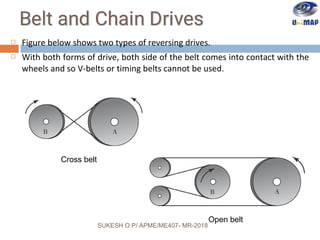
- 35. Figure below shows two types of reversing drives. With both forms of drive, both side of the belt comes into contact with the wheels and so V-belts or timing belts cannot be used. Cross belt Open belt SUKESH O P/ APME/ME407- MR-2018
- 36. SUKESH O P/ APME/ME407- MR-2018
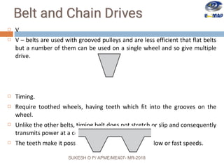
- 37. V V – belts are used with grooved pulleys and are less efficient that flat belts but a number of them can be used on a single wheel and so give multiple drive. Timing. Require toothed wheels, having teeth which fit into the grooves on the wheel. Unlike the other belts, timing belt does not stretch or slip and consequently transmits power at a constant angular velocity ratio. The teeth make it possible for the belt to be run at slow or fast speeds. SUKESH O P/ APME/ME407- MR-2018
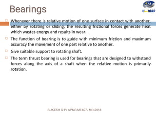
- 38. Whenever there is relative motion of one surface in contact with another, either by rotating or sliding, the resulting frictional forces generate heat which wastes energy and results in wear. The function of bearing is to guide with minimum friction and maximum accuracy the movement of one part relative to another. Give suitable support to rotating shaft. The term thrust bearing is used for bearings that are designed to withstand forces along the axis of a shaft when the relative motion is primarily rotation. SUKESH O P/ APME/ME407- MR-2018
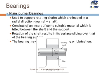
- 39. SUKESH O P/ APME/ME407- MR-2018
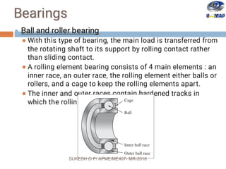
- 40. SUKESH O P/ APME/ME407- MR-2018
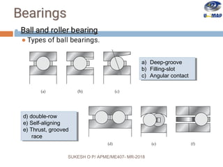
- 41. a) Deep-groove b) Filling-slot c) Angular contact a) Deep-groove b) Filling-slot c) Angular contact d) double-row e) Self-aligning e) Thrust, grooved race d) double-row e) Self-aligning e) Thrust, grooved race SUKESH O P/ APME/ME407- MR-2018
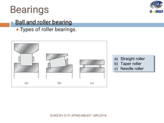
- 42. a) Straight roller b) Taper roller c) Needle roller a) Straight roller b) Taper roller c) Needle roller SUKESH O P/ APME/ME407- MR-2018
- 43. Electrical Actuators 10/16/18 43 SUKESH O P/ APME/ME407- MR-2018 An actuator receiving electrical energy for motion is called an electrical actuator. 1.Switching devices 1. Mechanical switches 1. Solenoids 2. Relays 2. Solid state switches 1. Diodes 2. Tyristors 3. Transistors 2.Drive system 1. DC motors 2. AC motors SUKESH O P/ APME/ME407- MR-2018
- 44. Hydraulics and Pneumatics 10/16/18 44 SUKESH O P/ APME/ME407- MR-2018SUKESH O P/ APME/ME407- MR-2018
- 45. Hydraulics An actuator wherein hydraulic energy is used to impart motion is called an hydraulic actuator. Hydraulic systems are power-transmitting assemblies employing pressurized liquid as a fluid for transmitting energy from an energy-generating source to an energy-using point to accomplish useful work. 10/16/18 45 SUKESH O P/ APME/ME407- MR-2018SUKESH O P/ APME/ME407- MR-2018
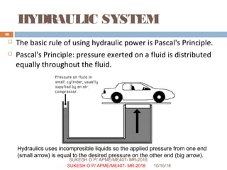
- 46. HYDRAULIC SYSTEM The basic rule of using hydraulic power is Pascal's Principle. Pascal's Principle: pressure exerted on a fluid is distributed equally throughout the fluid. 10/16/18 46 SUKESH O P/ APME/ME407- MR-2018 Hydraulics uses incompresible liquids so the applied pressure from one end (small arrow) is equal to the desired pressure on the other end (big arrow). SUKESH O P/ APME/ME407- MR-2018
- 47. Hydraulics 1. Hydraulic pump unit : in an actual hydraulic system a pump converts mechanical power into fluid power. 2. Control valve : the flow of pressurized liquid discharge by the pump is controlled by valves. Pressure control valves- control the liquid pressure . Flow control valves : control the liquid flow rate. Directional control valve : control the direction of flow of the liquid. 10/16/18 47 SUKESH O P/ APME/ME407- MR-2018SUKESH O P/ APME/ME407- MR-2018
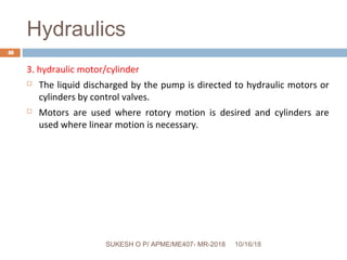
- 48. Hydraulics 3. hydraulic motor/cylinder The liquid discharged by the pump is directed to hydraulic motors or cylinders by control valves. Motors are used where rotory motion is desired and cylinders are used where linear motion is necessary. 10/16/18 48 SUKESH O P/ APME/ME407- MR-2018SUKESH O P/ APME/ME407- MR-2018
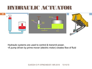
- 49. HYDRAULIC ACTUATOR 10/16/18SUKESH O P/ APME/ME407- MR-2018 49 Hydraulic systems are used to control & transmit power. •A pump driven by prime mover (electric motor) creates flow of fluid SUKESH O P/ APME/ME407- MR-2018
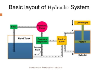
- 50. Hydraulic system 10/16/18SUKESH O P/ APME/ME407- MR-2018 50 SUKESH O P/ APME/ME407- MR-2018
- 51. 10/16/18SUKESH O P/ APME/ME407- MR-2018 51 SUKESH O P/ APME/ME407- MR-2018
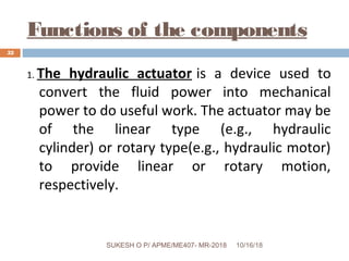
- 52. Functions of the components 1. The hydraulic actuator is a device used to convert the fluid power into mechanical power to do useful work. The actuator may be of the linear type (e.g., hydraulic cylinder) or rotary type(e.g., hydraulic motor) to provide linear or rotary motion, respectively. 10/16/18 52 SUKESH O P/ APME/ME407- MR-2018SUKESH O P/ APME/ME407- MR-2018
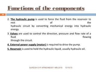
- 53. Functions of the components 2. The hydraulic pump is used to force the fluid from the reservoir to rest of the hydraulic circuit by converting mechanical energy into hydraulic energy. 3. Valves are used to control the direction, pressure and flow rate of a fluid flowing through the circuit. 4. External power supply (motor) is required to drive the pump. 5. Reservoir is used to hold the hydraulic liquid, usually hydraulic oil. 10/16/18 53 SUKESH O P/ APME/ME407- MR-2018SUKESH O P/ APME/ME407- MR-2018
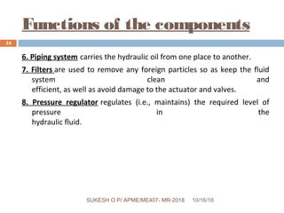
- 54. Functions of the components 6. Piping system carries the hydraulic oil from one place to another. 7. Filters are used to remove any foreign particles so as keep the fluid system clean and efficient, as well as avoid damage to the actuator and valves. 8. Pressure regulator regulates (i.e., maintains) the required level of pressure in the hydraulic fluid. 10/16/18 54 SUKESH O P/ APME/ME407- MR-2018SUKESH O P/ APME/ME407- MR-2018
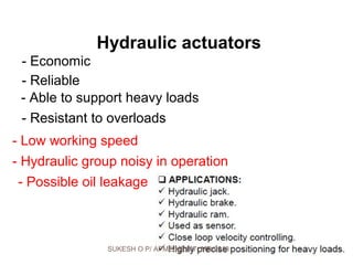
- 55. - Economic - Reliable - Resistant to overloads - Able to support heavy loads Hydraulic actuators - Low working speed - Hydraulic group noisy in operation - Possible oil leakage SUKESH O P/ APME/ME407- MR-2018
- 56. Pneumatics Uses pressurised air to transmit and control power. Air is used as the fluid because:- It is safe. It is less expensive and readily available It can be inducted and exhausted directly to the atmosphere and return line is not necessary as with hydraulics. 10/16/18 56 SUKESH O P/ APME/ME407- MR-2018SUKESH O P/ APME/ME407- MR-2018
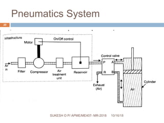
- 57. Pneumatics System 10/16/18 57 SUKESH O P/ APME/ME407- MR-2018SUKESH O P/ APME/ME407- MR-2018
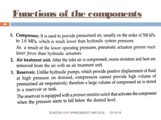
- 58. Functions of the components 10/16/18SUKESH O P/ APME/ME407- MR-2018 58 SUKESH O P/ APME/ME407- MR-2018
- 59. Functions of the components 10/16/18 59 SUKESH O P/ APME/ME407- MR-2018 Pneumatic systems are systems always processing new air (where as hydraulic systems are closed systems always returning the oil) SUKESH O P/ APME/ME407- MR-2018
- 60. Pneumatic actuators (cylinders) - Economic - Reliable - High operation speed - Resistant to overloads - Operation at constant force - No speed control - Poor position speed - Noisy operation SUKESH O P/ APME/ME407- MR-2018
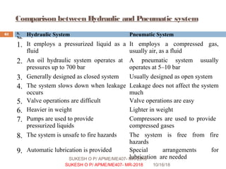
- 61. Comparison between Hydraulic and Pneumatic system 10/16/18 61 SUKESH O P/ APME/ME407- MR-2018 S. No. Hydraulic System Pneumatic System 1. It employs a pressurized liquid as a fluid It employs a compressed gas, usually air, as a fluid 2. An oil hydraulic system operates at pressures up to 700 bar A pneumatic system usually operates at 5–10 bar 3. Generally designed as closed system Usually designed as open system 4. The system slows down when leakage occurs Leakage does not affect the system much 5. Valve operations are difficult Valve operations are easy 6. Heavier in weight Lighter in weight 7. Pumps are used to provide pressurized liquids Compressors are used to provide compressed gases 8. The system is unsafe to fire hazards The system is free from fire hazards 9. Automatic lubrication is provided Special arrangements for lubrication are neededSUKESH O P/ APME/ME407- MR-2018
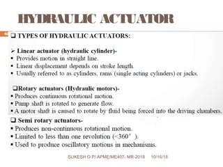
- 62. HYDRAULIC ACTUATOR 10/16/18 62 SUKESH O P/ APME/ME407- MR-2018SUKESH O P/ APME/ME407- MR-2018
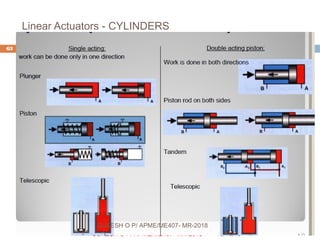
- 63. Linear Actuators - CYLINDERS 10/16/18 63 SUKESH O P/ APME/ME407- MR-2018 SUKESH O P/ APME/ME407- MR-2018
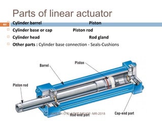
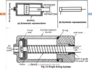
- 64. Parts of linear actuator Cylinder barrel Piston Cylinder base or cap Piston rod Cylinder head Rod gland Other parts : Cylinder base connection - Seals-Cushions 10/16/18SUKESH O P/ APME/ME407- MR-2018 64 SUKESH O P/ APME/ME407- MR-2018
- 65. 10/16/18 65 SUKESH O P/ APME/ME407- MR-2018SUKESH O P/ APME/ME407- MR-2018
- 66. 10/16/18 66 SUKESH O P/ APME/ME407- MR-2018SUKESH O P/ APME/ME407- MR-2018
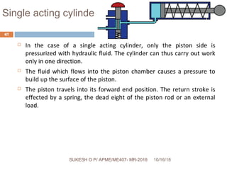
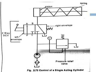
- 67. Single acting cylinder In the case of a single acting cylinder, only the piston side is pressurized with hydraulic fluid. The cylinder can thus carry out work only in one direction. The fluid which flows into the piston chamber causes a pressure to build up the surface of the piston. The piston travels into its forward end position. The return stroke is effected by a spring, the dead eight of the piston rod or an external load. 10/16/18 67 SUKESH O P/ APME/ME407- MR-2018SUKESH O P/ APME/ME407- MR-2018
- 68. 10/16/18 68 SUKESH O P/ APME/ME407- MR-2018SUKESH O P/ APME/ME407- MR-2018
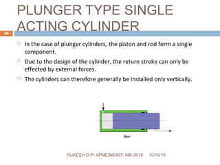
- 69. PLUNGER TYPE SINGLE ACTING CYLINDER In the case of plunger cylinders, the piston and rod form a single component. Due to the design of the cylinder, the return stroke can only be effected by external forces. The cylinders can therefore generally be installed only vertically. 10/16/18 69 SUKESH O P/ APME/ME407- MR-2018SUKESH O P/ APME/ME407- MR-2018
- 70. 10/16/18 70 SUKESH O P/ APME/ME407- MR-2018SUKESH O P/ APME/ME407- MR-2018
- 71. 10/16/18 71 SUKESH O P/ APME/ME407- MR-2018SUKESH O P/ APME/ME407- MR-2018
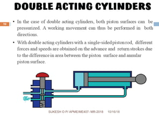
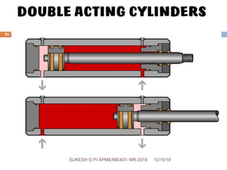
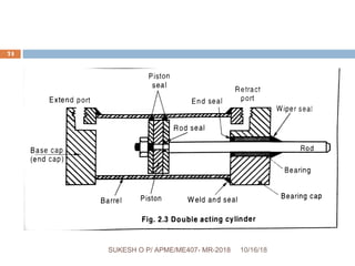
- 72. 10/16/18 72 SUKESH O P/ APME/ME407- MR-2018SUKESH O P/ APME/ME407- MR-2018
- 73. 10/16/18 73 SUKESH O P/ APME/ME407- MR-2018SUKESH O P/ APME/ME407- MR-2018
- 74. 10/16/18 74 SUKESH O P/ APME/ME407- MR-2018SUKESH O P/ APME/ME407- MR-2018
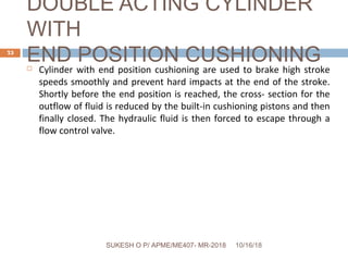
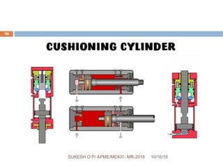
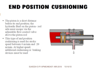
- 75. DOUBLE ACTING CYLINDER WITH END POSITION CUSHIONING Cylinder with end position cushioning are used to brake high stroke speeds smoothly and prevent hard impacts at the end of the stroke. Shortly before the end position is reached, the cross- section for the outflow of fluid is reduced by the built-in cushioning pistons and then finally closed. The hydraulic fluid is then forced to escape through a flow control valve. 10/16/18 75 SUKESH O P/ APME/ME407- MR-2018SUKESH O P/ APME/ME407- MR-2018
- 76. 10/16/18 76 SUKESH O P/ APME/ME407- MR-2018SUKESH O P/ APME/ME407- MR-2018
- 77. 10/16/18 77 SUKESH O P/ APME/ME407- MR-2018SUKESH O P/ APME/ME407- MR-2018
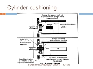
- 78. Cylinder cushioning 10/16/18 78 SUKESH O P/ APME/ME407- MR-2018SUKESH O P/ APME/ME407- MR-2018
- 79. 10/16/18 79 SUKESH O P/ APME/ME407- MR-2018SUKESH O P/ APME/ME407- MR-2018
- 80. 10/16/18 80 SUKESH O P/ APME/ME407- MR-2018SUKESH O P/ APME/ME407- MR-2018
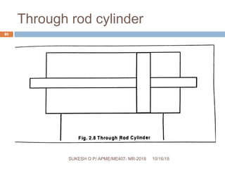
- 81. Through rod cylinder 10/16/18 81 SUKESH O P/ APME/ME407- MR-2018SUKESH O P/ APME/ME407- MR-2018
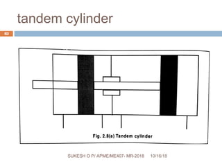
- 82. tandem cylinder 10/16/18 82 SUKESH O P/ APME/ME407- MR-2018SUKESH O P/ APME/ME407- MR-2018
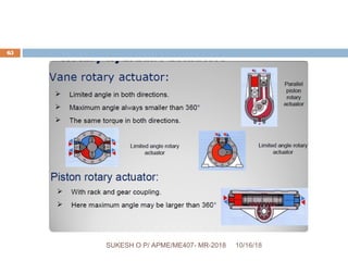
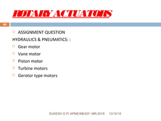
- 83. ROTARYACTUATORS ASSIGNMENT QUESTION HYDRAULICS & PNEUMATICS: : Gear motor Vane motor Piston motor Turbine motors Gerotor type motors 10/16/18 83 SUKESH O P/ APME/ME407- MR-2018SUKESH O P/ APME/ME407- MR-2018
- 84. Module-II Directional control valves, pressure control valves, process control valves. 10/16/18 84 SUKESH O P/ APME/ME407- MR-2018SUKESH O P/ APME/ME407- MR-2018
- 85. Control valves Fluid power is controlled primarily through the use of control devices called valves. Hydraulic and pneumatic systems require control valves to direct and regulate the flow of fluid and regulate the flow of fluid from pump(or compressor) to hydraulic cylinders or motors. 1. Direction control valves 2. Pressure control valves 3. Process control valves (flow) 10/16/18 85 SUKESH O P/ APME/ME407- MR-2018SUKESH O P/ APME/ME407- MR-2018
- 86. Flow control valves These valves are used to control the speed of hydraulic actuator by controlling the flow rate or discharge 1. Needle valve 2. Gate and globe valve SUKESH O P/ APME/ME407- MR-2018
- 87. 1. Needle valve It is the most common hydraulic flow control device. It consists of a needle or pointed threaded stem that can be adjusted manually to control the flow or discharge through the valve. It is made of steel. This valve can also be used as a stop valve to prevent the flow of fluid from one part of the hydraulic circuit to another. SUKESH O P/ APME/ME407- MR-2018
- 88. Needle valves SUKESH O P/ APME/ME407- MR-2018
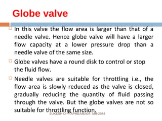
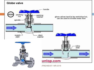
- 89. Globe valve In this valve the flow area is larger than that of a needle valve. Hence globe valve will have a larger flow capacity at a lower pressure drop than a needle valve of the same size. Globe valves have a round disk to control or stop the fluid flow. Needle valves are suitable for throttling i.e., the flow area is slowly reduced as the valve is closed, gradually reducing the quantity of fluid passing through the valve. But the globe valves are not so suitable for throttling function.SUKESH O P/ APME/ME407- MR-2018
- 90. SUKESH O P/ APME/ME407- MR-2018
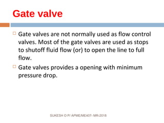
- 91. Gate valve Gate valves are not normally used as flow control valves. Most of the gate valves are used as stops to shutoff fluid flow (or) to open the line to full flow. Gate valves provides a opening with minimum pressure drop. SUKESH O P/ APME/ME407- MR-2018
- 92. SUKESH O P/ APME/ME407- MR-2018
- 93. Pressure control valvesPressure control valves These valves control the pressure of flow medium required by the system.. To regulate or reduce oil pressure in certain portions of the circuit to unload system pressure. To limit maximum system pressure as a safety measure. To assist sequential operation of actuators in a circuit by pressure control. To perform any other pressure related functions by virtue of pressure control.SUKESH O P/ APME/ME407- MR-2018
- 94. Types 1. Pressure relief valve. 2. Pressure sequencing valve. 3. Pressure reducing or regulating valve. 4. Pressure unloading valve. 5. Pressure brake valve. SUKESH O P/ APME/ME407- MR-2018
- 95. 1. Pressure relief valves These valves are found in every hydraulic system. It is normally closed valve, connected between the pressure line and the oil reservoir. Its main purpose is to limit the presure in a system to a prescribed maximum by diverting some or all of the pump output to the tanks, when the desired set pressure is reached. SUKESH O P/ APME/ME407- MR-2018
- 96. PRV SUKESH O P/ APME/ME407- MR-2018
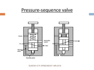
- 97. 2. Pressure sequencing valve Sequence valve is used to direct the flow to more than one portion of a fluid circuit in sequence. SUKESH O P/ APME/ME407- MR-2018
- 98. SUKESH O P/ APME/ME407- MR-2018
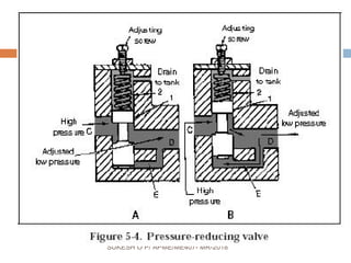
- 99. 3.Pressure reducing valve This type of valves are normally open pressure control valves used to maintain reduced pressures in certain portions of the hydraulic system. These are actuated by the pressure sensed in the branch circuit and tend to close as it reaches the pressure of the valve setting preventing further buildup of pressure. SUKESH O P/ APME/ME407- MR-2018
- 100. SUKESH O P/ APME/ME407- MR-2018
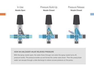
- 101. 4. Pressure unloading valve This type of valves is used to unload the energy in a system of a lower pressure. This valve allows pressure to build up to an adjustable setting and then bypasses the flow as long as a remote source maintains the preset pressure on the pilot port. Unloading valves are normally used in double pump applications. When the high speed and more flow are not required. SUKESHOP/APME/ME407- MR-2018
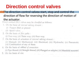
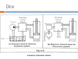
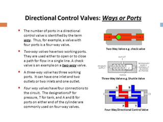
- 103. Direction control valves The direction control valvea start, stop and control the direction of flow for reversing the direction of motion of the actuator. SUKESHOP/APME/ME407- MR-2018
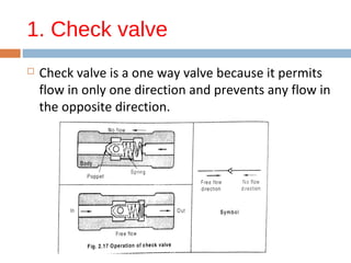
- 105. 1. Check valve Check valve is a one way valve because it permits flow in only one direction and prevents any flow in the opposite direction. SUKESHOP/APME/ME407- MR-2018
- 106. Pilot operated check valve The pilot operated check valve always permits free flow in one direction but permits flow in the normally blocked opposite direction only if pilot pressure pushes the pilot piston sownward. SUKESHOP/APME/ME407- MR-2018
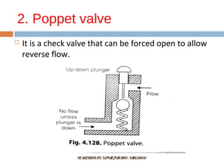
- 107. 2. Poppet valve It is a check valve that can be forced open to allow reverse flow. SUKESHOP/APME/ME407- MR-2018
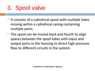
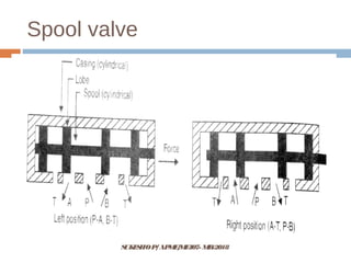
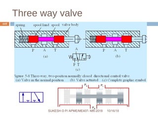
- 108. 3. Spool valve It consists of a cylindrical spool with multiple lobes moving within a cylindrical casing containing multiple ports. The spool can be moved back and fourth to align spaces between the spool lobes with input and output ports in the housing to direct high pressure flow to different circuits in the system. SUKESHOP/APME/ME407- MR-2018
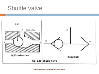
- 110. 4. Shuttle valve This is the another type of direction control valve. It allows a system to operate from either of two fluid power sources. It is also known as a double check valve. It is mostly used in pneumatic device and is rarely used in hydraulic circuits. SUKESHOP/APME/ME407- MR-2018
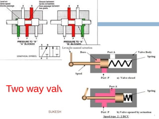
- 114. Two way valve 10/16/18 114 SUKESH O P/ APME/ME407- MR-2018SUKESH O P/ APME/ME407- MR-2018
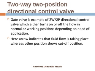
- 116. Two-way two-position directional control valve Gate valve is example of 2W/2P directional control valve which either turns on or off the flow in normal or working positions depending on need of application. Here arrow indicates that fluid flow is taking place whereas other position shows cut-off position. SUKESHOP/APME/ME407- MR-2018
- 117. Three way valve 10/16/18 117 SUKESH O P/ APME/ME407- MR-2018SUKESH O P/ APME/ME407- MR-2018
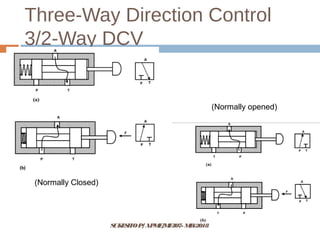
- 118. Three-Way Direction Control 3/2-Way DCV SUKESHOP/APME/ME407- MR-2018 (Normally Closed) (Normally opened)
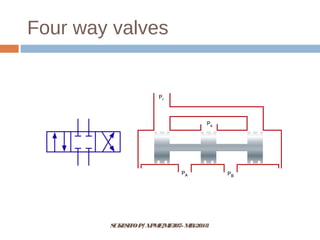
- 119. SUKESHOP/APME/ME407- MR-2018 Four way valves
- 120. Four way valves SUKESHOP/APME/ME407- MR-2018
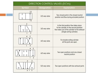
- 121. Four-way two-position directional control valve 4/2 valve has four connections to it and two valve positions. Normally, one port is open to flow from the pump. SUKESHOP/APME/ME407- MR-2018
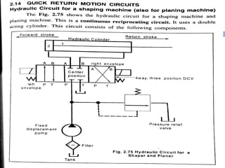
- 122. Four-way three-position directional control valve It has one way for pump (P), one for reservoir (R) or tank (T) and two for the inlet to the actuator. And it has 3 positions: one normal, one cross way, and one straight way. SUKESHOP/APME/ME407- MR-2018
- 123. SUKESHOP/APME/ME407- MR-2018 2POSITION , 2WAY DCV SINGLE ACTING HYDRAULIC CYLINDER CIRCUIT
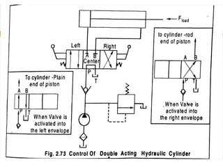
- 125. SUKESHOP/APME/ME407- MR-2018 Three position, four way DCV Double ACTING HYDRAULIC CYLINDER CIRCUIT