MET 401 Chapter 4 boilers_and_steam_generators
•Download as PPTX, PDF•
5 likes•4,302 views

The document discusses steam generators and boiler systems. It covers: 1. Steam generators are used to generate steam at desired rates, pressures, and temperatures for use in power plants. They use fuel combustion to heat water into steam. 2. Boiler systems comprise feedwater, steam, and fuel systems. Boilers are enclosed vessels that transfer combustion heat to water to produce heated water or steam for industrial processes. 3. There are two main types of boilers - fire tube and water tube. Fire tube boilers have combustion gases passing through tubes surrounded by water. Water tube boilers reverse this configuration.
Report
Share


MET 401 Chapter 4 boilers_and_steam_generators
- 1. MET 401 Power Plant Engineering Chapter 4 Boiler and steam generators Dr. Taib Iskandar Mohamad
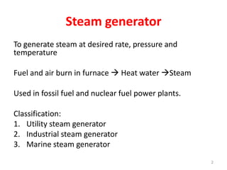
- 2. Steam generator To generate steam at desired rate, pressure and temperature Fuel and air burn in furnace Heat water Steam Used in fossil fuel and nuclear fuel power plants. Classification: 1. Utility steam generator 2. Industrial steam generator 3. Marine steam generator 2
- 3. Steam generator components • Economizer • Boiler • Superheater • Reheater • Air heater • Auxiliaries (ash handling, control, fan, burner etc) 3
- 4. 4
- 5. 5
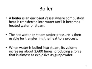
- 6. Boiler • A boiler is an enclosed vessel where combustion heat is transferred into water until it becomes heated water or steam. • The hot water or steam under pressure is then usable for transferring the heat to a process. • When water is boiled into steam, its volume increases about 1,600 times, producing a force that is almost as explosive as gunpowder. 6
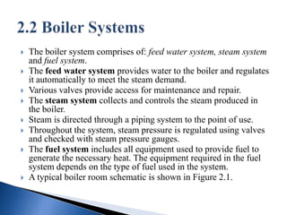
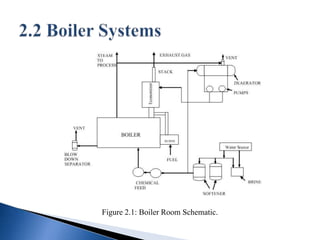
- 7. The boiler system comprises of: feed water system, steam system and fuel system. The feed water system provides water to the boiler and regulates it automatically to meet the steam demand. Various valves provide access for maintenance and repair. The steam system collects and controls the steam produced in the boiler. Steam is directed through a piping system to the point of use. Throughout the system, steam pressure is regulated using valves and checked with steam pressure gauges. The fuel system includes all equipment used to provide fuel to generate the necessary heat. The equipment required in the fuel system depends on the type of fuel used in the system. A typical boiler room schematic is shown in Figure 2.1.
- 8. Figure 2.1: Boiler Room Schematic.
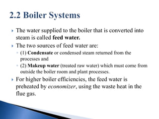
- 9. The water supplied to the boiler that is converted into steam is called feed water. The two sources of feed water are: ◦ (1) Condensate or condensed steam returned from the processes and ◦ (2) Makeup water (treated raw water) which must come from outside the boiler room and plant processes. For higher boiler efficiencies, the feed water is preheated by economizer, using the waste heat in the flue gas.
- 10. There are virtually infinite numbers of boiler designs but generally they fit into one of two categories: ◦ 1) Fire Tube Boiler, and ◦ 2) Water Tube Boiler.
- 11. Fire tube or ―fire in tube‖ boilers; contain long steel tubes through which the hot gasses from a furnace pass and around where the water to be converted to steam circulates. (Refer to Figure 2.2). Fire tube boilers, typically have a lower initial cost, are more fuel efficient and easier to operate, but they are limited generally to capacities of 25 tons/hr and pressures of 17.5 kg/cm2.
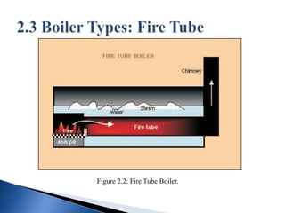
- 12. Figure 2.2: Fire Tube Boiler.
- 13. Water tube or ―water in tube‖ boilers in which the conditions are reversed with the water passing through the tubes and the hot gasses passing outside the tubes (see figure 2.3). These boilers can be of single- or multiple-drum type. These boilers can be built to any steam capacities and pressures, and have higher efficiencies than fire tube boilers.
- 14. Figure 2.3: Water Tube Boiler.
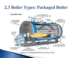
- 15. The packaged boiler is called so because it comes as a complete package. Once delivered to site, it requires only the steam, water pipe work, fuel supply and electrical connections to be made for it to become operational. Package boilers are generally of shell type with fire-tube design so as to achieve high heat transfer rates by both radiation and convection (Refer to Figure 2.4).
- 16. Figure 2.4: Packaged Boiler Cut-Away View.
- 17. Fire Tube Boiler Advantages: ◦ Relatively inexpensive. ◦ Easy to clean. ◦ Compact in size. ◦ Available in sizes from 176 kW/hr to 14,650 kW/hr. ◦ Easy to replace tubes. ◦ Well suited for space heating and industrial process applications.
- 18. Fire Tube Boiler Disadvantages: ◦ Not suitable for high pressure applications 1.72 MPa and above. ◦ Limitation for high capacity steam generation.
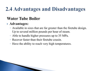
- 19. Water Tube Boiler Advantages: ◦ Available in sizes that are far greater than the firetube design. Up to several million pounds per hour of steam. ◦ Able to handle higher pressures up to 35 MPa. ◦ Recover faster than their firetube cousin. ◦ Have the ability to reach very high temperatures.
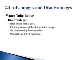
- 20. Water Tube Boiler Disadvantages: ◦ High initial capital cost. ◦ Cleaning is more difficult due to the design. ◦ No commonality between tubes. ◦ Physical size may be an issue.
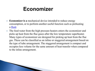
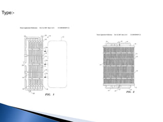
- 21. Economizer Economizer is a mechanical device intended to reduce energy consumption, or to perform another useful function such as preheating a fluid. The feed water from the high pressure heaters enters the economizer and picks up heat from the flue gases after the low temperature superheater. Many types of economizer are designed for picking up heat from the flue gas. These can be classified as an inline or staggered arrangement based on the type of tube arrangement. The staggered arrangement is compact and occupies less volume for the same amount of heat transfer when compared to the inline arrangement.
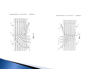
- 22. Economizers are also designed with 1- plain tube and 2- fined tubes. The fins can be longitudinal or spiral. All these types are suitable for clean fuels like gas, oil, and low ash coals. For high ash coals, only the plain tube inline arrangement is used. This is mainly to reduce ash erosion and thus reduce erosion failures. These economizers pick up about 50 to 55 degrees centigrade in a large capacity boiler, which will reduce the flue gas temperature by about 150 to 170 degree centigrade. The boiler designers always keep the economizer water outlet temperature to about 25 to 35 degrees below the drum saturation temperature. This is done to mainly avoid steaming in the economizer. A steaming economizer generally is less reliable. As a rule of thumb, for every one degree pick up of economizer water temperature, there will be a drop of about 3 to 3.5 degrees
- 23. Type:-
- 25. Economizer Advantages :- 1- A lowering of the flue gas temperature by 100 C 2- will improve the efficient rate by 5% 3- No falling below the dew point. 4- It does not cause condensation. 5- No special requirement on the material for flue gas ducts and chimney. 6- Sufficient thermal buoyancy for the flue gases
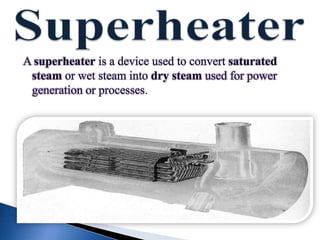
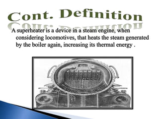
- 26. A superheater is a device used to convert saturated steam or wet steam into dry steam used for power generation or processes.
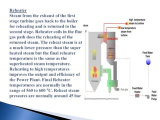
- 32. An air reheater (APH) is a general term to describe any device designed to heat air before another process (for example, combustion in a boiler) with the primary objective of increasing the thermal efficiency of the process. They may be used alone or to replace a recuperative heat system or to replace a steam coil.
- 33. Tubular type Operation: Tubular reheaters consist of straight tube bundles which pass through the outlet ducting of the boiler and open at each end outside of the ducting. Inside the ducting, the hot furnace gases pass around the reheater tubes, transferring heat from the exhaust gas to the air inside the reheater.
- 34. The tubular reheater ductings for cold and hot air require more space and structural supports than a rotating reheater design
- 35. Operation: In this design the whole air preheater casing is supported on the boiler supporting structure itself with necessary expansion joints in the ducting. The vertical rotor is supported on thrust bearings at the lower end and has an oil bath lubrication, cooled by water circulating in coils inside the oil bath. This arrangement is for cooling the lower end of the shaft, as this end of the vertical rotor is on the hot end of the ducting. The top end of the rotor has a simple roller bearing to hold the shaft in a vertical position.
- 36. The boiler flue gas contains many dust particles (due to high ash content) not contributing towards combustion, such as silica, which cause abrasive wear of the baskets, and may also contain corrosive gases depending on the composition of the fuel.
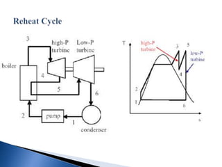
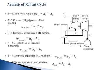
- 40. 1—2: Isentropic Pumping w h2 h1 p 2 –3 Constant (High)pressure Heat addition q in , SG h3 h2 3 –4 Isentropic expansion in HP turbine. w hp , out h3 h4 4—5 Constant (Low) Pressure Reheating. q in , RH h5 h4 5 – 6 Isentropic expansion in LP turbine. w lp , out h5 h6 6 – 1 Constant pressure condensation. q out h6 h1