


Minor losses valve
- 1. Erbil Polytechnic University Koya Technical Institute Petroleum Technology Operation and Control Report Fluid Mechanic Lab. Test no: (10) Test name: (Minor Losses) Supervised by: Karwan A. Ali Date of Test: 12/04/2018 Date of Submit: 3/05/2018 Prepared by: Muhammed Shwan Ali
- 2. Title Page No. Introduction 3 Aim of the experiment 3 Unit description 3-6 Calculation 7-16 Discussion 16-17 Table of Calculation 18
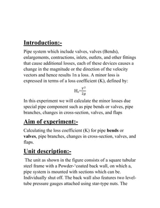
- 3. -Introduction: Pipe system which include valves, valves (Bends), enlargements, contractions, inlets, outlets, and other fittings that cause additional losses, each of these devices causes a change in the magnitude or the direction of the velocity vectors and hence results 1n a loss. A minor loss is expressed in terms of a loss coefficient (K), defined by: 𝑉2 2𝑔 =eH In this experiment we will calculate the minor losses due special pipe component such as pipe bends or valves, pipe branches, changes in cross-section, valves, and flaps -Aim of experiment: Calculating the loss coefficient (K) for pipe bends or valves, pipe branches, changes in cross-section, valves, and flaps. -Unit description: The unit as shown in the figure consists of a square tubular steel frame with a Powder-‘coated back wall, on which a, pipe system is mounted with sections which can be. Individually shut off. The back wall also features two level- tube pressure gauges attached using star-type nuts. The
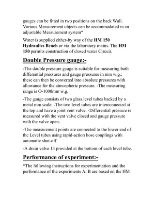
- 4. gauges can be fitted in two positions on the back Wall. Various Measurement objects can be accommodated in an adjustable Measurement system“ Water is supplied either-by way of the HM 150 Hydraulics Bench or via the laboratory mains. The HM 150 permits construction of closed water Circuit. -gauge:PressureDouble -The double pressure gauge is suitable for measuring both differential pressures and gauge pressures in mm w.g.; these can then be converted into absolute pressures with allowance for the atmospheric pressure. -The measuring range is O-1000mm w.g. -The gauge consists of two glass level tubes backed by a metal mm scale. -The two level tubes are interconnected at the top and have a joint vent valve. -Differential pressure is measured with the vent valve closed and gauge pressure with the valve open. -The measurement points are connected to the lower end of the Level tubes using rapid-action hose couplings with automatic shut-off. -A drain valve 13 provided at the bottom of each level tube. -of experiment:Performance *The following instructions for experimentation and the performance of the experiments A, B are based on the HM
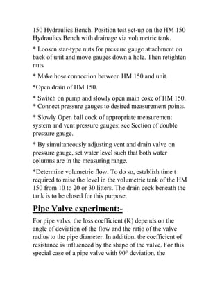
- 5. 150 Hydraulics Bench. Position test set-up on the HM 150 Hydraulics Bench with drainage via volumetric tank. * Loosen star-type nuts for pressure gauge attachment on back of unit and move gauges down a hole. Then retighten nuts * Make hose connection between HM 150 and unit. *Open drain of HM 150. * Switch on pump and slowly open main coke of HM 150. * Connect pressure gauges to desired measurement points. * Slowly Open ball cock of appropriate measurement system and vent pressure gauges; see Section of double pressure gauge. * By simultaneously adjusting vent and drain valve on pressure gauge, set water level such that both water columns are in the measuring range. *Determine volumetric flow. To do so, establish time t required to raise the level in the volumetric tank of the HM 150 from 10 to 20 or 30 litters. The drain cock beneath the tank is to be closed for this purpose. -experiment:ValvePipe For pipe valvs, the loss coefficient (K) depends on the angle of deviation of the flow and the ratio of the valve radius to the pipe diameter. In addition, the coefficient of resistance is influenced by the shape of the valve. For this special case of a pipe valve with 90° deviation, the
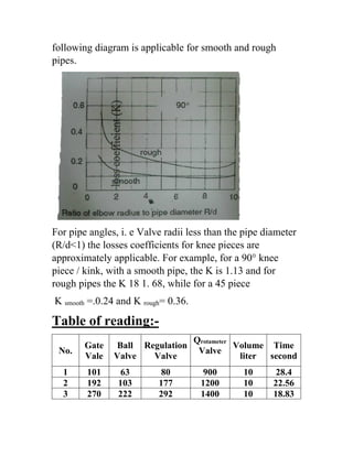
- 6. following diagram is applicable for smooth and rough pipes. For pipe angles, i. e Valve radii less than the pipe diameter (R/d<1) the losses coefficients for knee pieces are approximately applicable. For example, for a 90° knee piece / kink, with a smooth pipe, the K is 1.13 and for rough pipes the K 18 1. 68, while for a 45 piece = 0.36.rough=.0.24 and KsmoothK -ng:Table of readi Time second Volume liter Qrotameter Valve Regulation Valve Ball Valve Gate Vale No. 28.41090080631011 22.561012001771031922 18.831014002922222703
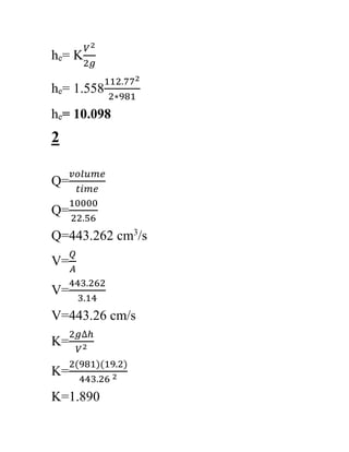
- 7. -Calculation: 3 Volume=10000cm2 A=3.14cmD=20mm Gate valve Q= 𝑣𝑜𝑙𝑢𝑚𝑒 𝑡𝑖𝑚𝑒 Q= 10000 28.24 /s3 Q=354.1 cm V= 𝑄 𝐴 V= 354.1 3.14 V=112.77 cm/s K= 2𝑔∆ℎ 𝑉2 K= 2(981)(10.1) 112.772 K=1.558
- 8. 𝑉2 2𝑔 = Keh 112.772 2∗981 = 1.558eh 10.098=eh 2 Q= 𝑣𝑜𝑙𝑢𝑚𝑒 𝑡𝑖𝑚𝑒 Q= 10000 22.56 /s3 Q=443.262 cm V= 𝑄 𝐴 V= 443.262 3.14 V=443.26 cm/s K= 2𝑔∆ℎ 𝑉2 K= 2(981)(19.2) 443.26 2 K=1.890
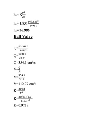
- 9. 𝑉2 2𝑔 = Keh 141.162 2∗981 1.890=eh 19.194=eh 3 Q= 𝑣𝑜𝑙𝑢𝑚𝑒 𝑡𝑖𝑚𝑒 Q= 10000 18.83 /s3 Q=531.06 cm V= 𝑄 𝐴 V= 531.06 3.14 V=169.129 cm/s K= 2𝑔∆ℎ 𝑉2 K= 2(981)(27) 169.129 2 K=1.851
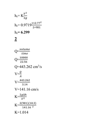
- 10. 𝑉2 2𝑔 = Keh 169.1292 2∗981 = 1.851eh 26.986=eh Ball Valve Q= 𝑣𝑜𝑙𝑢𝑚𝑒 𝑡𝑖𝑚𝑒 Q= 10000 28.24 /s3 Q=354.1 cm V= 𝑄 𝐴 V= 354.1 3.14 V=112.77 cm/s K= 2𝑔∆ℎ 𝑉2 K= 2(981)(6.3) 112.772 K=0.9719
- 11. 𝑉2 2𝑔 = Keh 112.772 2∗981 = 0.9719eh 6.299=eh 2 Q= 𝑣𝑜𝑙𝑢𝑚𝑒 𝑡𝑖𝑚𝑒 Q= 10000 22.56 /s3 Q=443.262 cm V= 𝑄 𝐴 V= 443.262 3.14 V=141.16 cm/s K= 2𝑔∆ℎ 𝑉2 K= 2(981)(10.3) 141.16 2 K=1.014
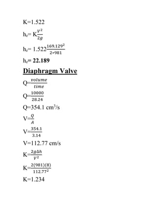
- 12. 𝑉2 2𝑔 = Keh 141.162 2∗981 1.014=eh 10.298=eh 3 Q= 𝑣𝑜𝑙𝑢𝑚𝑒 𝑡𝑖𝑚𝑒 Q= 10000 18.83 /s3 Q=531.06 cm V= 𝑄 𝐴 V= 531.06 3.14 V=169.129 cm/s K= 2𝑔∆ℎ 𝑉2 K= 2(981)(22.2) 169.129 2
- 13. K=1.522 𝑉2 2𝑔 = Keh 169.1292 2∗981 1.522=eh 22.189=eh ValveDiaphragm Q= 𝑣𝑜𝑙𝑢𝑚𝑒 𝑡𝑖𝑚𝑒 Q= 10000 28.24 /s3 Q=354.1 cm V= 𝑄 𝐴 V= 354.1 3.14 V=112.77 cm/s K= 2𝑔∆ℎ 𝑉2 K= 2(981)(8) 112.772 K=1.234
- 14. 𝑉2 2𝑔 = Keh 112.772 2∗981 = 1.234eh 7.998=eh 2 Q= 𝑣𝑜𝑙𝑢𝑚𝑒 𝑡𝑖𝑚𝑒 Q= 10000 22.56 /s3 Q=443.262 cm V= 𝑄 𝐴 V= 443.262 3.14 V=141.16 cm/s K= 2𝑔∆ℎ 𝑉2 K= 2(981)(17.7) 141.16 2 K=1.7428
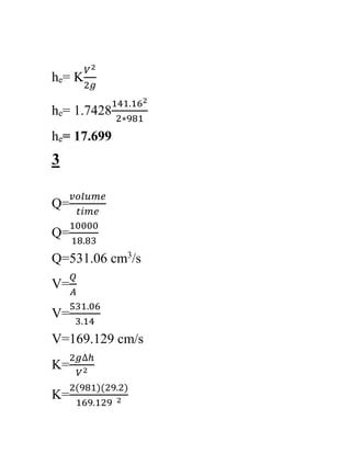
- 15. 𝑉2 2𝑔 = Keh 141.162 2∗981 1.7428=eh 17.699=eh 3 Q= 𝑣𝑜𝑙𝑢𝑚𝑒 𝑡𝑖𝑚𝑒 Q= 10000 18.83 /s3 Q=531.06 cm V= 𝑄 𝐴 V= 531.06 3.14 V=169.129 cm/s K= 2𝑔∆ℎ 𝑉2 K= 2(981)(29.2) 169.129 2
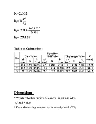
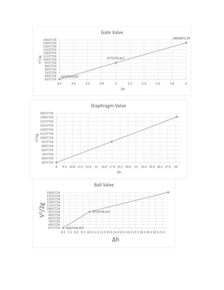
- 16. K=2.002 𝑉2 2𝑔 = Keh 169.1292 2∗981 2.002=eh 29.187=eh Table of Calculation: V (cm/s) Pipe elbow No. Diaphragm ValveBall ValveGate Valve he (cm) K Δh (cm) he (cm) K Δh (cm) he (cm) K Δh (cm) 112.777.9981.23486.2990.97196.310.0981.55810.11 141.1617.6991.742817.710.2981.01410.319.1941.89019.22 169.1229.1872.00229.222.1891.52222.226.9861.851273 -Discussion: * Which valve has minimum loss coefficient and why? A/ Ball Valve ./2g2 * Draw the relating between Ah & velocity head V
- 17. 6237724.257 9773774.417 14029072.24 6237724 6937724 7637724 8337724 9037724 9737724 10437724 11137724 11837724 12537724 13237724 13937724 14637724 4.2 4.4 4.6 4.8 5 5.2 5.4 5.6 5.8 6 V2/2g Δh Gate Valve 6237724.257 9773774.417 6237724 6937724 7637724 8337724 9037724 9737724 10437724 11137724 11837724 12537724 13237724 13937724 6.3 7.3 8.3 9.3 10.3 11.3 12.3 13.3 14.3 15.3 16.3 17.3 18.3 19.3 20.3 21.3 V2/2g Δh Ball Valve 6237724 6937724 7637724 8337724 9037724 9737724 10437724 11137724 11837724 12537724 13237724 13937724 14637724 8 9.4 10.8 12.2 13.6 15 16.4 17.8 19.2 20.6 22 23.4 24.8 26.2 27.6 29 V2/2g Δh Diaphragm Valve