Piping design and flexibility analysis
•
14 likes•3,273 views

This document summarizes a student project to design a high temperature and pressure naphtha piping system. It includes the project members, objectives to understand piping design concepts and flexibility, and perform stress analysis manually and using CAESER II software. The problem statement is to design a 6" diameter pipe connecting a centrifugal pump and pressure vessel operating at 300°C and 21.4kg/cm2. The document outlines the design methodology, calculations, material selection, and references used.
Report
Share

Piping design and flexibility analysis
- 2. PROJECT GUIDES: DR. S JAYAKUMAR (INTERNAL) MR. SAJISH, SR. ENGG. BPCL KOCHI REFINERY(EXTERNAL) PROJECT GROUP MEMBERS ANOOP M G DEEPIKA SUDEVAN SARATH KRISHNAKUMAR TOBIN MAMMEN
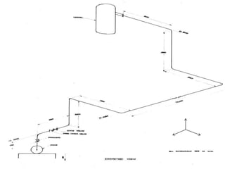
- 3. To understand the concepts of piping design and flexibility of piping PROBLEM STATEMENT :To design a high temperature (300deg Celsius), high pressure (21.4kg/cm2) NAPHTHA carrying pipe connecting the given centrifugal pump and a pressure vessel. The pipe is of 6” diameter and the pump outlet is of 4” diameter. To perform stress analysis of the system– manually. To verify the design using CAESER II.
- 4. HOOP STRESS –circumferential stress or tensile stress acting in a direction tangential to the circumference. Mathematically, Hoop stress = (P x D)/(2xt) Therefore pipe wall thickness “t” can be obtained FLEXIBILITY- piping systems shall have sufficient flexibility to prevent thermal expansion or contraction or movements of piping support and terminals. D y ≤ 0.03 (L-U)2
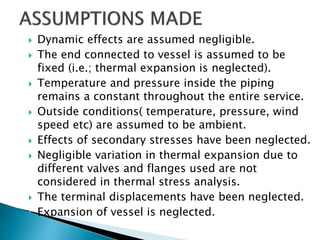
- 5. Dynamic effects are assumed negligible. The end connected to vessel is assumed to be fixed (i.e.; thermal expansion is neglected). Temperature and pressure inside the piping remains a constant throughout the entire service. Outside conditions( temperature, pressure, wind speed etc) are assumed to be ambient. Effects of secondary stresses have been neglected. Negligible variation in thermal expansion due to different valves and flanges used are not considered in thermal stress analysis. The terminal displacements have been neglected. Expansion of vessel is neglected.
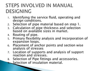
- 6. 1. Identifying the service fluid, operating and design conditions. 2. Selection of pipe material based on step 1. 3. Calculation of pipe thickness and selection based on available sizes in market. 4. Routing of pipe. 5. Primary flexibility analysis and incorporation of expansion loops. 6. Placement of anchor points and section wise analysis of stresses 7. Location of supports and analysis of support reaction and stresses. 8. Selection of Pipe fittings and accessories. 9. Selection of insulation material.
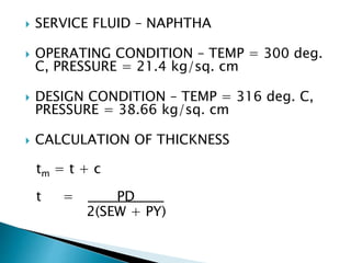
- 7. SERVICE FLUID – NAPHTHA OPERATING CONDITION – TEMP = 300 deg. C, PRESSURE = 21.4 kg/sq. cm DESIGN CONDITION – TEMP = 316 deg. C, PRESSURE = 38.66 kg/sq. cm CALCULATION OF THICKNESS tm = t + c t = PD 2(SEW + PY)
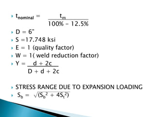
- 8. tnominal = tm 100% - 12.5% D = 6” S =17.748 ksi E = 1 (quality factor) W = 1( weld reduction factor) Y = d + 2c D + d + 2c STRESS RANGE DUE TO EXPANSION LOADING Sb = √(Sb 2 + 4St 2)
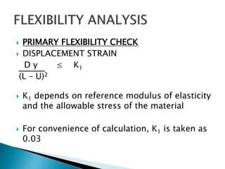
- 10. PRIMARY FLEXIBILITY CHECK DISPLACEMENT STRAIN D y ≤ K1 (L – U)2 K1 depends on reference modulus of elasticity and the allowable stress of the material For convenience of calculation, K1 is taken as 0.03
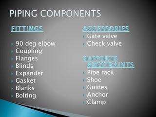
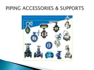
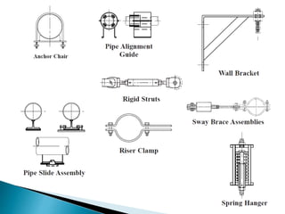
- 12. 90 deg elbow Coupling Flanges Blinds Expander Gasket Blanks Bolting Gate valve Check valve Pipe rack Shoe Guides Anchor Clamp
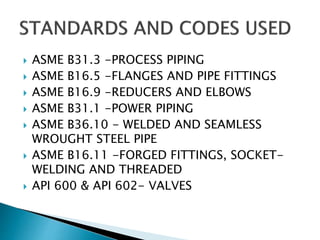
- 15. ASME B31.3 -PROCESS PIPING ASME B16.5 -FLANGES AND PIPE FITTINGS ASME B16.9 -REDUCERS AND ELBOWS ASME B31.1 -POWER PIPING ASME B36.10 - WELDED AND SEAMLESS WROUGHT STEEL PIPE ASME B16.11 -FORGED FITTINGS, SOCKET- WELDING AND THREADED API 600 & API 602- VALVES
- 16. The manual designing process and stress analysis have been completed The design is found to be safe
- 17. “PIPING DESIGN AND ENGINEERING”-by ITT GRINNELL INDUSTRIAL PIPING INC. ASME CAREER COURSE MATERIAL “PIPING AND PIPE SUPPORT SYSTEMS” –by PAUL R SMITH & THOMAS J VAN LAAN “ASME CODE BOOKS”