Pressure control valves
•Download as PPTX, PDF•
22 likes•26,999 views

The document summarizes different types of pressure control valves used in hydraulic systems. It describes pressure relief valves, pressure reducing valves, unloading valves, counterbalance valves, and pressure sequence valves. Each type of valve is explained in terms of its working, symbol, and purpose of controlling pressure in hydraulic circuits. Compound versions of some valves are also discussed.
Report
Share


Pressure control valves
- 1. Gujarat Power Engineering & Research Institute 1 Oil Hydraulics & Pneumatics Prepared By:- Patel Pranav V. (131040119042) Guided By:- Prof. Parin Patel 10/17/2016
- 2. Pressure Control Valves The controller of Actuator Pressure
- 3. Pressure Control Valves • In order to avoid hydraulic system damage, power wastage and overheating of the hydraulic fluid, circuit designers use a variety of cleverly designed systems to control maximum system pressure and pump flow during non-action periods. • Pressure-control valves are used in hydraulic systems to control actuator force (force = pressure × area)and to determine and select pressure levels at which certain machine operations must occurs. ACTUATOR FORCE = Pressure(P)* Area(A).
- 4. Functions • Limiting maximum system pressure at a safe level. • Regulating/reducing pressure in certain portions of the circuit. • Unloading system pressure. • Assisting sequential operation of actuators in a circuit with pressure control. • Any other pressure-related function by virtue of pressure control. • Reducing or stepping down pressure levels from the main circuit to a lower pressure in a sub-circuit.
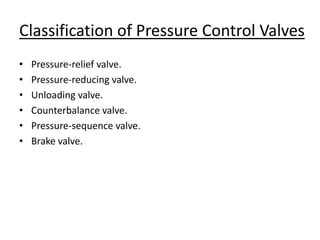
- 5. Classification of Pressure Control Valves • Pressure-relief valve. • Pressure-reducing valve. • Unloading valve. • Counterbalance valve. • Pressure-sequence valve. • Brake valve.
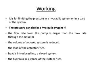
- 7. Working • It is for limiting the pressure in a hydraulic system or in a part of the system. • The pressure can rise in a hydraulic system if: - the flow rate from the pump is larger than the flow rate through the actuator - the volume of a closed system is reduced. - the load of the actuator rises. - heat is introduced into a closed system. - the hydraulic resistance of the system rises.
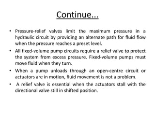
- 8. Continue... • Pressure-relief valves limit the maximum pressure in a hydraulic circuit by providing an alternate path for fluid flow when the pressure reaches a preset level. • All fixed-volume pump circuits require a relief valve to protect the system from excess pressure. Fixed-volume pumps must move fluid when they turn. • When a pump unloads through an open-centre circuit or actuators are in motion, fluid movement is not a problem. • A relief valve is essential when the actuators stall with the directional valve still in shifted position.
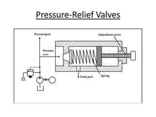
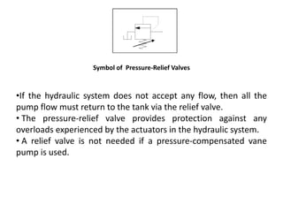
- 9. Symbol of Pressure-Relief Valves •If the hydraulic system does not accept any flow, then all the pump flow must return to the tank via the relief valve. • The pressure-relief valve provides protection against any overloads experienced by the actuators in the hydraulic system. • A relief valve is not needed if a pressure-compensated vane pump is used.
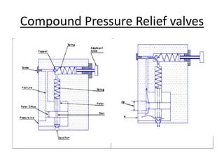
- 10. Compound Pressure Relief valves
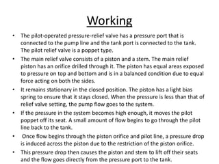
- 11. Working • The pilot-operated pressure-relief valve has a pressure port that is connected to the pump line and the tank port is connected to the tank. The pilot relief valve is a poppet type. • The main relief valve consists of a piston and a stem. The main relief piston has an orifice drilled through it. The piston has equal areas exposed to pressure on top and bottom and is in a balanced condition due to equal force acting on both the sides. • It remains stationary in the closed position. The piston has a light bias spring to ensure that it stays closed. When the pressure is less than that of relief valve setting, the pump flow goes to the system. • If the pressure in the system becomes high enough, it moves the pilot poppet off its seat. A small amount of flow begins to go through the pilot line back to the tank. • Once flow begins through the piston orifice and pilot line, a pressure drop is induced across the piston due to the restriction of the piston orifice. • This pressure drop then causes the piston and stem to lift off their seats and the flow goes directly from the pressure port to the tank.
- 13. Working • This type of valve (which is normally open) is used to maintain reduced pressures in specified locations of hydraulic systems. It is actuated by downstream pressure and tends to close as this pressure reaches the valve setting. • A pressure-reducing valve uses a spring-loaded spool to control the downstream pressure. If downstream pressure is below the valve setting, the fluid flows freely from the inlet to the outlet. • When the outlet (downstream) pressure increases to the valve setting, the spool moves to the right to partially block the outlet port. Just enough flow is passed to the outlet to maintain its preset pressure level. If the valve closes completely, leakage past the spool causes downstream pressure to build up above the valve setting.
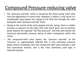
- 14. Compound Pressure-reducing valve • The "pressure override" which is caused by the direct-acting relief valve may find applications in some areas. However, in others it may result in a considerable input-power loss owing to the fluid lost through the valve during the wide "pressure override" band. • Owing to the inertia of the valve poppet and the spring, there is sudden increase in pressure on the valve inlet side which gives rise to pressure peaks beyond the adjusted "full flow pressure" and may well exceed the maximum permissible pressure rating of other components within the circuit. • The compound-relief valve lowers the "pressure override" to the minimum i.e. approximately 100-150 KPa. It also eliminates pressure peaks almost completely, thus the compound relief valve provides a safe and economical solution, and is the most commonly used type in industrial systems.
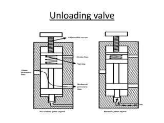
- 15. Unloading valve
- 16. Working • Unloading valves are pressure-control devices that are used to dump excess fluid to the tank at little or no pressure. • A common application is in high-low pump circuits where two pumps move an actuator at high speed and low pressure. The circuit then shifts to a single pump providing a high pressure to perform work. • Another application is sending excess flow from the cap end of an oversize-rod cylinder to the tank as the cylinder retracts. • This makes it possible to use a smaller, less-expensive directional control valve while keeping pressure drop low.
- 17. Compound Unloading valve • A pilot-operated unloading relief valve is the same as a pilot- operated relief valve with the addition of an unloading spool. • Without the unloading spool, this valve would function just like any pilot-operated relief valve. • Pressure build up in the pilot section would open some flow to the tank and unbalance the poppet, allowing it to open and relieve excess pump flow.
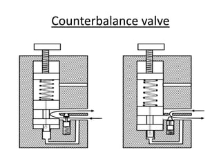
- 19. Working • These normally closed valves are primarily used to maintain a back pressure on a vertical cylinder to prevent it from falling due to gravity. • They are used to prevent a load from accelerating uncontrollably. This situation can occur in vertical cylinders in which the load is a weight. • This can damage the load or even the cylinder itself when the load is stopped quickly at the end of the travel. • This situation can occur in vertical cylinders in which the load is a weight. This can damage the load or even the cylinder itself when the load is stopped quickly at the end of the travel. valve’s primary port is connected to the cylinder’s rod end and the secondary port to the directional • control valve. The pressure setting is slightly higher than that required to keep the load from free-falling. • When the pressurized fluid flows to the cylinder’s cap end, the cylinder extends, increasing pressure in the rod end and shifting the main spool in the counterbalance valve. This creates a path that permits the fluid to flow through the secondary port via the directional control valve and to the reservoir. As the load is raised, the integral check valve opens to allow the cylinder to retract freely.
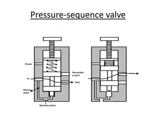
- 21. Working • A sequence valve is a pressure-control valve that is used to force two actuators to operate in sequence. • Instead of sending flow back to the tank, a sequence valve allows flow to a branch circuit, when a preset pressure is reached. • The check valve allows the sequence valve to be bypassed in the reverse direction. • The component enclosure line indicates that the check valve is an integral part of the component. The sequence valve has an external drain line; therefore, a line must be connected from the sequence valve’s drain port to the tank.