Location via proxy:   [ UP ]  
[Report a bug]   [Manage cookies]                
SlideShare a Scribd company logo
Department of Aerospace Engineering
                                   AE 212 Mechanics of Solids

 Tutorial 9    Date 29/10/2012          Topics covered: Pressure Vessels and Combined Loadings

1. The open ended pipe has a wall thickness of 2 mm and an internal diameter of 40 mm. Calculate the
   pressure that ice exerted on the interior wall of the pipe to cause it to burst in the manner shown.
   The maximum stress that the material can support at freezing temperature is                    .Show
   the stress acting on a small element of material just before the pipe fails.

2. The open ended polyvinyl chloride pipe has an inner diameter of 40 mm and thickness of 2 mm. If it
   carries flowing water at 60 N/mm2 pressure, determine the state of stress in the walls of the pipe. If
   the flow of water within the pipe is stopped due to the closing of a valve, determine the state of
   stress in the walls of the pipe. Neglect the weight of the water. Assume the supports only exert
   vertical forces on the pipe.


3. The ring having the dimensions shown, is placed over a flexible membrane which is pumped up with
   a pressure p. Determine the change in the internal radius of the ring after this pressure is applied.
   The modulus of elasticity for the ring is E.

4. The steel band is 2 cm wide and is secured around the smooth rigid cylinder. If the bolts are
   tightened so that the tension in them is 400 N, determine the normal stress in the band, the pressure
   exerted on the cylinder and the distance the half the band stretches. E=210GPa
5. The cylinder of negligible weight rests on a smooth floor. Determine the eccentric distance        at
   which the load can be placed so that the normal stress at pint A is zero.


6. If P=15kN, plot the distribution of stress acting over the cross section    of the offset link.


7. The bar has a diameter of 40 mm. If it is subjected to the two force components at its ends as shown,
   determine the state of stress at point A and show the results on a differential volume element
   located at this point.
1. Determine the maximum deflection using moment area theorems for the following beams.
2. Determine the elastic curve for beam using the coordinates specified and determine the
   maximum slope and maximum deflection. EI is constant.


3. The beam is made of ceramic material.In order to obtain its modulus of elasticity,it is
   subjected to elastic loading as shown below.If the moment of inertia is I and the beam has
   measured maximum deflection of ,determine E.


4. The simply supported shaft has a moment of inertia of 2I for region BC and a moment of
   inertia of I for regions AB and CD. Determine the maximum deflection of the shaft due to the
   load P. Modulus of elasticity is E.
5. Determine the deflection at the end B of the clamped steel strip. The spring has a stiffness of
   k=2 N/mm. The strip is 5 mm wide and 10 mm high. Also draw the shear and moment
   diagrams for the strip.


6. If the bearing exerts only vertical reactions on the shaft, determine the slope at the bearings
   and the maximum deflection of the shaft. EI is constant. Use Moment Area Theorems.
Tutorial 9
Tutorial 9
Tutorial 9
Tutorial 9
Tutorial 9
Tutorial 9
Tutorial 9

More Related Content

Tutorial 9

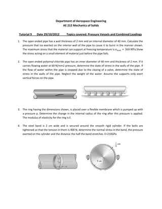
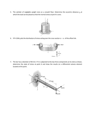
  • 1. Department of Aerospace Engineering AE 212 Mechanics of Solids Tutorial 9 Date 29/10/2012 Topics covered: Pressure Vessels and Combined Loadings 1. The open ended pipe has a wall thickness of 2 mm and an internal diameter of 40 mm. Calculate the pressure that ice exerted on the interior wall of the pipe to cause it to burst in the manner shown. The maximum stress that the material can support at freezing temperature is .Show the stress acting on a small element of material just before the pipe fails. 2. The open ended polyvinyl chloride pipe has an inner diameter of 40 mm and thickness of 2 mm. If it carries flowing water at 60 N/mm2 pressure, determine the state of stress in the walls of the pipe. If the flow of water within the pipe is stopped due to the closing of a valve, determine the state of stress in the walls of the pipe. Neglect the weight of the water. Assume the supports only exert vertical forces on the pipe. 3. The ring having the dimensions shown, is placed over a flexible membrane which is pumped up with a pressure p. Determine the change in the internal radius of the ring after this pressure is applied. The modulus of elasticity for the ring is E. 4. The steel band is 2 cm wide and is secured around the smooth rigid cylinder. If the bolts are tightened so that the tension in them is 400 N, determine the normal stress in the band, the pressure exerted on the cylinder and the distance the half the band stretches. E=210GPa
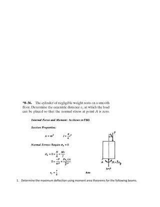
  • 2. 5. The cylinder of negligible weight rests on a smooth floor. Determine the eccentric distance at which the load can be placed so that the normal stress at pint A is zero. 6. If P=15kN, plot the distribution of stress acting over the cross section of the offset link. 7. The bar has a diameter of 40 mm. If it is subjected to the two force components at its ends as shown, determine the state of stress at point A and show the results on a differential volume element located at this point.
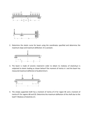
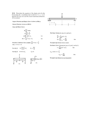
  • 3. 1. Determine the maximum deflection using moment area theorems for the following beams.
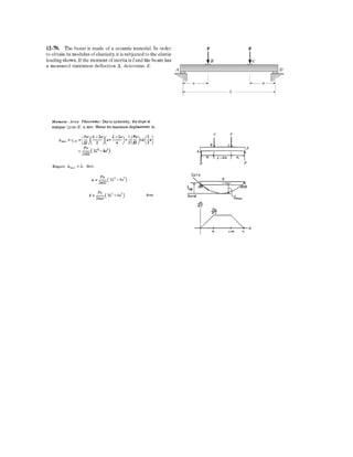
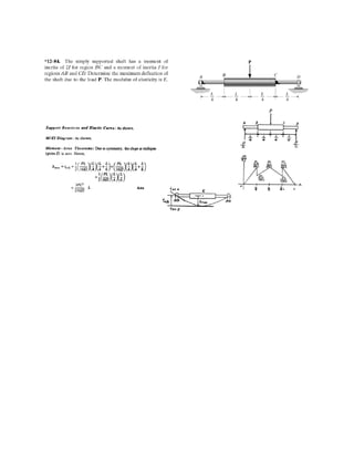
  • 4. 2. Determine the elastic curve for beam using the coordinates specified and determine the maximum slope and maximum deflection. EI is constant. 3. The beam is made of ceramic material.In order to obtain its modulus of elasticity,it is subjected to elastic loading as shown below.If the moment of inertia is I and the beam has measured maximum deflection of ,determine E. 4. The simply supported shaft has a moment of inertia of 2I for region BC and a moment of inertia of I for regions AB and CD. Determine the maximum deflection of the shaft due to the load P. Modulus of elasticity is E.
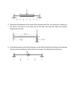
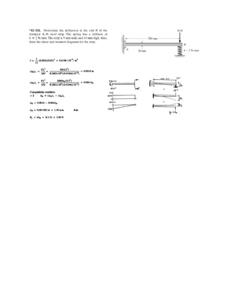
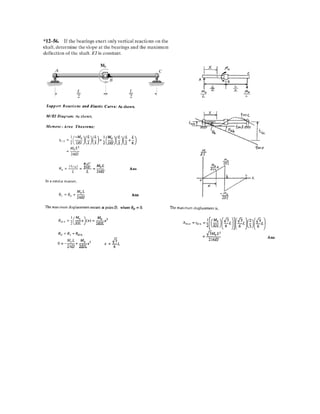
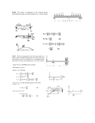
  • 5. 5. Determine the deflection at the end B of the clamped steel strip. The spring has a stiffness of k=2 N/mm. The strip is 5 mm wide and 10 mm high. Also draw the shear and moment diagrams for the strip. 6. If the bearing exerts only vertical reactions on the shaft, determine the slope at the bearings and the maximum deflection of the shaft. EI is constant. Use Moment Area Theorems.