Location via proxy:   [ UP ]  
[Report a bug]   [Manage cookies]                
  • Featured in Physics
  • Open Access

Performance-Optimized Components for Quantum Technologies via Additive Manufacturing

S.H. Madkhaly, L.A. Coles, C. Morley, C.D. Colquhoun, T.M. Fromhold, N. Cooper, and L. Hackermüller
PRX Quantum 2, 030326 – Published 12 August 2021
Physics logo See synopsis: 3D-Printed Components for Cold Atoms

Abstract

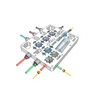
Novel quantum technologies and devices place unprecedented demands on the performance of experimental components, while their widespread deployment beyond the laboratory necessitates increased robustness and fast affordable production. We show how the use of additive manufacturing, together with mathematical optimization techniques and innovative designs, allows the production of compact lightweight components with greatly enhanced performance. We use such components to produce a magneto-optical trap that captures approximately 2×10⁸ rubidium atoms, employing for this purpose a compact and highly stable device for spectroscopy and optical power distribution, optimized neodymium magnet arrays for magnetic field generation, and a lightweight additively manufactured ultrahigh-vacuum chamber. We show how the use of additive manufacturing enables substantial weight reduction and stability enhancement, while also illustrating the transferability of our approach to experiments and devices across the quantum technology sector and beyond.

  • Figure
  • Figure
  • Figure
  • Figure
  • Figure
  • Figure
  • Figure
4 More
  • Received 2 March 2021
  • Accepted 28 June 2021

DOI:https://doi.org/10.1103/PRXQuantum.2.030326

Published by the American Physical Society under the terms of the Creative Commons Attribution 4.0 International license. Further distribution of this work must maintain attribution to the author(s) and the published article's title, journal citation, and DOI.

Published by the American Physical Society

Physics Subject Headings (PhySH)

Atomic, Molecular & Optical

synopsis

Key Image

3D-Printed Components for Cold Atoms

Published 12 August 2021

Researchers demonstrate lighter, smaller optics and vacuum components for cold-atom experiments that they hope could enable the development of portable quantum technologies.

See more in Physics

Authors & Affiliations

S.H. Madkhaly1,2,*, L.A. Coles3, C. Morley1, C.D. Colquhoun1, T.M. Fromhold1, N. Cooper1,†, and L. Hackermüller1,‡

  • 1School of Physics and Astronomy, University of Nottingham, University Park, Nottingham NG7 2RD, United Kingdom
  • 2Department of Physics, Jazan University, Jazan 45142, Kingdom of Saudi Arabia
  • 3Added Scientific Ltd., Unit 4, Isaac Newton Centre, Nottingham NG7 2RH, United Kingdom

  • *somaya1407@gmail.com
  • nathan.cooper@nottingham.ac.uk
  • lucia.hackermuller@nottingham.ac.uk

Popular Summary

Quantum technologies are set to have a dramatic impact on both science and society, transforming fields as diverse as brain imaging, geophysical surveying, and space-borne fundamental-physics experiments. However, the hardware upon which these technologies depend is typically large, expensive, difficult to use, and highly susceptible to environmental noise. To enable the widespread rollout of quantum technologies, the required hardware must become more portable, cheaper, and more robust. We demonstrate a range of quantum technology hardware components with improved robustness and greatly reduced size and weight. Furthermore, we use these components to illustrate a more general experimental design methodology, which can be applied to numerous quantum technology components across a wide range of disciplines.

The principle that underpins our new components is the use of additive manufacturing (AM) to directly implement the results of design and optimization processes, freeing components from the constraints imposed by conventional manufacturing. This enables rapid device prototyping and dramatic reductions in size and weight. Reduced system size typically then leads to improved robustness against environmental disturbance. The customizability afforded by AM, together with the increased component alignment tolerances resulting from reduced overall system size, also enables the elimination of many adjustable components from conventional systems; this improves stability, decreases requirements on user expertise, and further reduces size and weight.

It is expected that these results will establish a new paradigm for experimental design, particularly in the area of free-space optics, and to facilitate the development of smaller, cheaper, more robust quantum devices, both inside and outside the laboratory.

Key Image

Article Text

Click to Expand

References

Click to Expand
Issue

Vol. 2, Iss. 3 — August - October 2021

Reuse & Permissions
Author publication services for translation and copyediting assistance advertisement

Authorization Required


×

Images

  • Figure 1
    Figure 1

    An overview of the complete setup, showing 3D-printed and optimized components in the areas marked with dashed boxes A, B, and C. A indicates the distributed feedback lasers (DFBs) used as master light sources, B indicates the compact spectroscopy and power-distribution (CSPD) apparatus, and C indicates the trapping apparatus including the AM UHV chamber, the optimized permanent-magnet arrays, and a set of self-aligning AM fiber outcoupler mounts. The setup takes up a volume of 0.15 m3 and the custom parts indicated have a cumulative mass of 3.2 kg.

    Reuse & Permissions
  • Figure 2
    Figure 2

    A photograph of a butterfly-packaged DFB laser and optical isolator (indicated with the dashed rectangle) in an AM mount. Note how the DFB laser module is mounted such that the original base plate remains exposed to the air, to facilitate passive cooling.

    Reuse & Permissions
  • Figure 3
    Figure 3

    The CSPD apparatus. (a) A 3D render of the mount. The holes that can be used as fiber inputs or outputs are indicated. (b) A photograph of the CSPD with optics, a reference cell, and fibers adhered to the appropriate positions. (c),(d) Close-ups of the wave-plate and beam-splitter slots. The rounded recesses on the edges and corners prevent scuffing of the optically active surfaces and improve push fit alignment accuracy, respectively.

    Reuse & Permissions
  • Figure 4
    Figure 4

    A schematic of the optics layout in the CSPD and how each input laser beam is directed through it. The purple beams represent reference light, the orange beams cooler light, and the green beams repumper light.

    Reuse & Permissions
  • Figure 5
    Figure 5

    (a) The laser locking frequencies relative to 85Rb D2 transitions and the corresponding saturated absorption spectroscopy features of the (b) cooler and (c) repumper beams. (d) The spectroscopic error signal for the cooler laser (see text for details). The form of the signal can be seen to remain consistent and appropriate for feedback stabilization of the laser frequency despite substantial variations in environmental temperature. Note that vertical offsets of 0.1, 0.05, 0, 0.05, 0.1, and 0.15 V are added to the displayed signals (in order of increasing temperature, respectively), to improve visibility.

    Reuse & Permissions
  • Figure 6
    Figure 6

    A 3D model of the vacuum chamber seen in Fig. 1, without the lattice structure. The blue rings attached to the top and bottom of the chamber represent the permanent-magnet arrays.

    Reuse & Permissions
  • Figure 7
    Figure 7

    Grids of the possible positions for two different types of magnetized voxels: (a) diameter of 6 mm and depth of 3 mm; (b) diameter of 6 mm and depth of 6 mm. The optimized arrangements to produce a MOT field are shown in (c) and (d) for the initial grids of (a) and (b), respectively. The geometry in (d) is used as a basis for the magnet rings shown in Fig. 6, as the increased distance between the rings and the trapping region is necessary to accommodate the vacuum chamber.

    Reuse & Permissions
  • Figure 8
    Figure 8

    (a) A graph showing the similarities between the numerically calculated fields produced by the optimized magnet structure (circles and squares) of Fig. 7 and target magnetic fields (lines) for Bx along the x direction (blue) and Bz along the z direction (red). (b) A comparison between the numerically calculated and the experimentally measured axial magnetic field components produced by a single ring of magnetic voxels, along the axis of the ring, versus the distance from the ring (see text for details).

    Reuse & Permissions
  • Figure 9
    Figure 9

    The fluorescence image of the cloud of cold 85Rb atoms captured by our MOT, which is produced using the optimized components described herein.

    Reuse & Permissions
  • Figure 10
    Figure 10

    MOT loading curves based on fluorescence data for various values of the Rb dispenser current. The colored lines show raw data and the black lines are fits to the data based on Eq. (4).

    Reuse & Permissions
  • Figure 11
    Figure 11

    The error signals resulting from saturated absorption spectroscopy (with laser current modulation and phase-sensitive detection) of (a) the 85Rb D2 line |F=2|F=1,2,3 “repumper” transition and (b) the 85Rb |F=3|F=2,3,4 “reference” transition. The red curves represent the signals generated when only the laser performing the spectroscopy is present in the vapor cell, while the blue lines represent the signals obtained when a beam resonant with the other transition spatially overlapped with this beam in the same vapor cell. As can be seen from the figures, optical pumping effects result in an enhancement of the error signal amplitude—particularly for the laser addressing the repumper transition.

    Reuse & Permissions
×

Sign up to receive regular email alerts from PRX Quantum

Reuse & Permissions

It is not necessary to obtain permission to reuse this article or its components as it is available under the terms of the Creative Commons Attribution 4.0 International license. This license permits unrestricted use, distribution, and reproduction in any medium, provided attribution to the author(s) and the published article's title, journal citation, and DOI are maintained. Please note that some figures may have been included with permission from other third parties. It is your responsibility to obtain the proper permission from the rights holder directly for these figures.

×

Log In

Cancel
×

Search


Article Lookup

Paste a citation or DOI

Enter a citation
×