Location via proxy:   [ UP ]  
[Report a bug]   [Manage cookies]                
  • Open Access

3-Fermion Topological Quantum Computation

Sam Roberts and Dominic J. Williamson
PRX Quantum 5, 010315 – Published 2 February 2024

Abstract

We present a scheme for universal topological quantum computation based on Clifford-complete braiding and fusion of symmetry defects in the 3-fermion anyon theory, supplemented with magic state injection. We formulate a fault-tolerant measurement-based realization of this computational scheme on the lattice using ground states of the Walker-Wang model for the 3-fermion anyon theory with symmetry defects. The Walker-Wang measurement-based topological quantum computation paradigm that we introduce provides a general construction of computational resource states with thermally stable symmetry-protected topological order. We also demonstrate how symmetry defects of the 3-fermion anyon theory can be realized in a two-dimensional subsystem code due to Bombín—making contact with an alternative implementation of the 3-fermion defect-computation scheme via code deformations.

  • Figure
  • Figure
  • Figure
  • Figure
  • Figure
  • Figure
  • Figure
27 More
  • Received 23 December 2021
  • Revised 23 August 2023
  • Accepted 8 September 2023

DOI:https://doi.org/10.1103/PRXQuantum.5.010315

Published by the American Physical Society under the terms of the Creative Commons Attribution 4.0 International license. Further distribution of this work must maintain attribution to the author(s) and the published article's title, journal citation, and DOI.

Published by the American Physical Society

Physics Subject Headings (PhySH)

Quantum Information, Science & TechnologyCondensed Matter, Materials & Applied Physics

Authors & Affiliations

Sam Roberts1,* and Dominic J. Williamson2

  • 1Centre for Engineered Quantum Systems, School of Physics, The University of Sydney, Sydney, New South Wales 2006, Australia
  • 2Stanford Institute for Theoretical Physics, Stanford University, Stanford, California 94305, USA

  • *samroberts1737@gmail.com

Popular Summary

Large-scale quantum computers promise to revolutionize the way we solve many important information-processing tasks. Essential to their design is the use of quantum error correction in order to protect delicate quantum information from noise due to imperfect components and operations as well as unwanted interactions with the environment. Significant advances in fault-tolerant quantum computation have been made by developing schemes based on exotic interacting spin models in two-dimensional (2D) lattices called topological phases, but despite many advances, the resource requirements to implement these complex quantum error-correction schemes remain a formidable challenge. Moving from two to three dimensions, the possible phases of matter are much richer, but it is not known how to utilize them for quantum computation.

In this work, we harness the topological order of a rich set of three-dimensional (3D) spin lattices for fault-tolerant quantum computation, offering compelling alternatives to the main approaches that are currently being pursued. With these exotic models, information can be encoded and protected on their 2D boundaries—acting as a topological quantum memory—and processed using measurements on individual spin qubits in the 3D bulk. Focusing on a promising example known as the 3-fermion model, we show how to perform a universal set of fault-tolerant gates by leveraging the underlying symmetries of the model to create defects in the spin lattice (akin to crystal defects). The computational scheme we present is inherently robust, as errors on the spins can be detected using the same measurements that drive the computation and subsequently corrected.

Our computational scheme provides an ingress to exploit the exotic physics present in 3D topological phases to perform efficient fault-tolerant gates on protected qubits that may enable large-scale quantum computation to be realized in the near future.
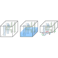
Key Image

Article Text

Click to Expand

References

Click to Expand
Issue

Vol. 5, Iss. 1 — February - April 2024

Reuse & Permissions
Author publication services for translation and copyediting assistance advertisement

Authorization Required


×

Images

  • Figure 1
    Figure 1

    A fermion αC is transformed by the symmetry group to gαC under a counterclockwise braid with a twist Tg.

    Reuse & Permissions
  • Figure 2
    Figure 2

    The elementary twist-defect configuration for encoding quantum information. One or two logical qubits are encoded if gS3 is a 2-cycle (e.g., (rg)) or a 3-cycle (e.g., (rgb)), respectively.

    Reuse & Permissions
  • Figure 3
    Figure 3

    Representative fermionic string operators for logical Pauli operators for a g encoding. (a) A single qubit is encoded in four twists defined by (rg)S3. Note also in this case that the orientation has been removed from the domain wall, as (rg)1=(rg). Similar representative logical operators for twist defects based on the other 2-cycles gS3 can be obtained by suitably permuting the fermionic string-operator types. (b) Two qubits are encoded in four twists defined by (rgb),(rbg)S3.

    Reuse & Permissions
  • Figure 4
    Figure 4

    The equivalence between different representative fermionic string operators for logical Pauli X¯ operators for the two-twist-pair encoding for g encodings—in this case, g=(rg). They can be verified by the fusion rule for ψr×ψg=ψb, along with the fact that T(rg) can condense ψb fermions.

    Reuse & Permissions
  • Figure 5
    Figure 5

    One-qubit gates for the defect encoding E(rg). Time moves upward. (a) The Hadamard gate cyclically permutes the four twist defects. A domain-wall plane is inserted to return the encoding to its standard form. (b) The S gate consists of the exchange of T(rg)(3) and T(rg)(4). The same gates work for a g encoding, with g a 2-cycle—in this case, the orientation of the surface does not matter and is not depicted.

    Reuse & Permissions
  • Figure 6
    Figure 6

    A two-qubit cz gate between pairs of qubits with g and h encodings with 2-cycles ghS3, e.g., g=(rg) on the left and h=(rb) on the right. Time moves upward. The domain walls are colored according to the fermion that they leave invariant. In Appendix pp2, we show how to generate entangling gates between two (rg)-encoded qubits.

    Reuse & Permissions
  • Figure 7
    Figure 7

    (a) The preparation of X¯ eigenstates. (b) The preparation of Z¯ eigenstates. We depict the operation for a (rg) encoding. Time moves upward. To prepare either X¯ or Z¯ eigenstates, we need to prepare pairs of twists in definite charge states. This can be done by nucleating them out of vacuum so that we know that they fuse to the identity anyon (i.e., no charge). To obtain the respective measurements, we take the time-reverse diagram (i.e., tt). This works identically for any gS3 and we note that when g is a 3-cycle, both encoded qubits are prepared (or measured) in the same basis.

    Reuse & Permissions
  • Figure 8
    Figure 8

    The preparation of a nontopologically protected magic state. Time moves upward. Four twists are brought into close proximity such that a nontopological operation can be implemented (depicted by the shaded neighborhood around all four twists on the leftmost figure)—in this case, to prepare |T¯=12(|0¯+eiπ4|1¯). The precise nature of the nontopological projection depends on the lattice implementation. Topologically, the projection can be understood as giving rise to a superposition of a X¯ and Z¯ eigenstate preparations.

    Reuse & Permissions
  • Figure 9
    Figure 9

    (a) The special edges Of and Uf for each plaquette orientation. The coordinate system is shown, with each edge of the lattice being length 1. (b) An example of the Hamiltonian terms Bf(ψr) and Bf(ψg).

    Reuse & Permissions
  • Figure 10
    Figure 10

    The 3F Walker-Wang plaquette terms after translation of each of the τ qubits in the original lattice by 12(1,1,1). σ qubits live on edges, while τ qubits live on faces. The supports of the terms B~f(ψr) and B~e(ψg) are shown at the top and bottom, respectively. For a given face f, the edges Uf,Of are precisely those depicted that are not in the boundary of the face. Similarly, for a given edge e, the faces Ue and Oe are those depicted that are not in the coboundary of the edge. The 1-form constraint terms A~v(ψr) and A~q(ψg) are given by a product of Pauli-X operators on the star of a vertex and the boundary of a cube, respectively.

    Reuse & Permissions
  • Figure 11
    Figure 11

    An example of a domain-wall plane D for a symmetry S(rg) ending in a twist (depicted in solid blue) traveling in the y^ direction. The new Hilbert space contains no qubits on any of the shaded edges or faces, leaving a lattice dislocation.

    Reuse & Permissions
  • Figure 12
    Figure 12

    The boundary of H3F. The blue-shaded region depicts vacuum (i.e., a region with no qubits) and the bulk of H3F lies above the plane. (a) The stabilizers on the boundary: truncated versions of Av(ψr) and Bf(ψr) shaded in red and of Av(ψg) and Bf(ψg) shaded in green. (b) The support of logical operators of Eqs. (30) and (31)—two cycles, c and c, are depicted by solid red and green lines, while the links belonging to cO and cO are depicted by dashed lines. For example, if we take periodic boundary conditions (such that the boundary is a torus), then the two operators lcψr and lcψg form anticommuting pairs of logical operators.

    Reuse & Permissions
  • Figure 13
    Figure 13

    (a) The Walker-Wang construction applied to the toric code anyon theory CTC gives the plaquette terms depicted above. Terms on different plaquettes can be obtained by translating and rotating according to the correct orientation, as depicted by the blue and red legs. (b) The 3D cluster-state terms obtained after all τ qubits have been translated by 12(1,1,1). All terms are rotationally symmetric on this lattice.

    Reuse & Permissions
  • Figure 14
    Figure 14

    Fault-tolerant MBQC using the 3F Walker-Wang model. (a) Defects and twists can be discretized to live on 2-chains of the lattice and their boundary. (b) Measurements in the fermion basis in the blue region drive the computation. (c) The postmeasured state is given by a fixed fermion world-line string net. Any violations of the Z2×Z2 conservation at each vertex results from an error and is detected by the vertex operators, the outcomes of which are inferred from the local measurements.

    Reuse & Permissions
  • Figure 15
    Figure 15

    The preparation of 3F surface states on the boundaries of A and B by measuring all sites in C. The planes c(xy) and c(zy) are depicted in red and green, respectively, with the cycles c(xy) and c(zy) on their boundary. The set of links cO(xy) and cO(zy) are the set perpendicular to the surfaces, on the same side as the dashed lines on A. The set of links cU(xy) and cU(zy) are on the opposite side.

    Reuse & Permissions
  • Figure 16
    Figure 16

    Syndromes observed in Walker-Wang MBQC. The lines are color coded according to the observed measurement outcomes corresponding to the basis |1:=|++, |ψr:=|+, |ψg:=|+, |ψb:=|. Possible errors producing the observed syndrome are displayed by dashed lines. Nontrivial syndromes sv=(a,b)Z22 on each vertex are observed due to violations of the Z22 charge flux on each vertex and can be inferred from the measurement outcomes of (Av(ψr),Av(ψg)). For example, s1=(1,0) and s3=(1,1) arises from ψr and ψb string errors, as depicted.

    Reuse & Permissions
  • Figure 17
    Figure 17

    Undetectable errors in Walker-Wang MBQC, depicted by dashed lines. The homologically trivial loops do not result in a logical error. The central error depicted in blue that extends between different twists results in a logical error.

    Reuse & Permissions
  • Figure 18
    Figure 18

    The tricoloring of hexagonal plaquettes used to define the generators of the anomalous Z2×Z2 1-form symmetry.

    Reuse & Permissions
  • Figure 19
    Figure 19

    (a) An inflated hexagon. (b) There are three different types of x, y, and z links in the lattice, respectively.

    Reuse & Permissions
  • Figure 20
    Figure 20

    (a) The WpX generator on the inflated hexagon. (b) The WpZ generator on the inflated hexagon. The WpY generator is given by their product.

    Reuse & Permissions
  • Figure 21
    Figure 21

    Segments of the string operators that form the anomalous Z2×Z2 1-form symmetry.

    Reuse & Permissions
  • Figure 22
    Figure 22

    A π3 lattice disclination on a plaquette that hosts twist defects of a Z2 symmetry generator.

    Reuse & Permissions
  • Figure 23
    Figure 23

    (a) A 2π3 lattice disclination on an inflated vertex that hosts twist defects of the Z3 symmetry generator. (b) A lattice dislocation on a plaquette that can also host twist defects of the Z3 symmetry generator.

    Reuse & Permissions
  • Figure 24
    Figure 24

    Correlation surfaces for the Hadamard and phase gates. Time moves upward. (a) Correlation surfaces for X¯Z¯ and Z¯X¯ in the Hadamard gate. (b) Correlation surfaces for X¯Y¯ and Z¯Z¯ in the phase gate.

    Reuse & Permissions
  • Figure 25
    Figure 25

    Correlation surfaces illustrating the action of the cz gate. Time moves upward. We see (a) Z¯2Z¯2 and (b) X¯2X¯2Z¯1. One can similarly confirm Z¯1Z¯1 and X¯1X¯1Z¯2 using directly analogous correlation surfaces. This action on the four generating Pauli operators uniquely determines the cz gate.

    Reuse & Permissions
  • Figure 26
    Figure 26

    Correlation surfaces for the X¯ and Z¯ preparations. Time travels upward. At the topmost time slice, the state is an eigenstate of either logical X¯ or Z¯. Logical measurements are obtained by time reversing the diagrams.

    Reuse & Permissions
  • Figure 27
    Figure 27

    The index convention for a single logical qubit.

    Reuse & Permissions
  • Figure 28
    Figure 28

    A circuit that implements cz between the two qubits on the top wires. The circuit is composed of operations that are implementable via elementary gates outlined in the main text. Here, MX is a Pauli-X measurement. In particular, this circuit is designed to implement a cz gate between two (rg)-encoded qubits (top two wires) using an (rb)-encoded ancilla (bottom wire).

    Reuse & Permissions
  • Figure 29
    Figure 29

    Braid diagrams for (a) the H gate and (b) the S gate. The strings denote the twists T(rg)—labeled 1–4—that must be braided. From left to right, the twists are labeled T(rg)(1), T(rg)(2), T(rg)(3), and T(rg)(4), according to Fig. 2.

    Reuse & Permissions
  • Figure 30
    Figure 30

    Braid diagrams for the cz gate. The strings denote the twists T(rg), T(rb)—labeled 1–8—that must be braided. The first four represent the first encoded qubit and the second four represent the second encoded qubit. Note that from left to right, the twists are arranged as T(rg)(1), T(rg)(2), T(rg)(3), T(rg)(4), T(rb)(1), T(rb)(2), T(rb)(3), and T(rb)(4), according to the twist labeling of Fig. 2.

    Reuse & Permissions
  • Figure 31
    Figure 31

    (a) Two equivalent representations of a g encoding. The precise location of the domain walls does not matter, only their endpoint. (b) The two encodings are isotopic up to a spacelike domain wall. The domain-wall configuration that achieves this is depicted on the right, where for simplicity we have ignored orientation.

    Reuse & Permissions
  • Figure 32
    Figure 32

    A trijunction encoding. (a) A configuration of twist defects defined by g,hS3. We must have either gh or g=h and both g and h are 3-cycles in order to have a valid trijunction that encodes qubits: if we have exactly one of g and h a 3-cycle, then we encode one logical qubit; if both g,h=(rgb) or (rgb)1, then we encode two qubits. (b) Trijunction encoding with g=h=(gh)1=(rgb). Depicted are a set of fermionic Wilson loops that form a generating set of logical Pauli operators.

    Reuse & Permissions
  • Figure 33
    Figure 33

    Example 3F Walker-Wang terms along the (rg)S3 domain wall depicted in Fig. 11. The terms are color coded according to their support: blue-shaded faces denote the domain wall D—upon which no qubits are supported; magenta-shaded faces and edges denote the presence of τX and σX, respectively; yellow-shaded faces and edges denote the presence of τZ and σZ, respectively. The top row of terms may be regarded as transformed versions of the rightmost terms of Fig. 10 that intersect the domain-wall plane, while the bottom row are the transformed 1-form terms A~v(ψr) and A~q(ψg).

    Reuse & Permissions
  • Figure 34
    Figure 34

    Example 3F Walker-Wang terms along the (rg)S3 twist depicted in Fig. 11. The twist travels along the central vertical edge, depicted by the dotted blue line. The left term can be regarded as the transformed version of rightmost term of Fig. 33 along the twist (obtained by multiplying a plaquette by its image under translation, each restricted to the qubits on the complement of the defect). Similarly, the modified 1-form operators contain τY to ensure correct commutation. Other terms can be obtained by translating in the y^ direction but we remark that these terms alone do not form a complete set. The color coding is identical to that of Fig. 33, with the addition of τY being denoted by checkered teal faces.

    Reuse & Permissions
×

Sign up to receive regular email alerts from PRX Quantum

Reuse & Permissions

It is not necessary to obtain permission to reuse this article or its components as it is available under the terms of the Creative Commons Attribution 4.0 International license. This license permits unrestricted use, distribution, and reproduction in any medium, provided attribution to the author(s) and the published article's title, journal citation, and DOI are maintained. Please note that some figures may have been included with permission from other third parties. It is your responsibility to obtain the proper permission from the rights holder directly for these figures.

×

Log In

Cancel
×

Search


Article Lookup

Paste a citation or DOI

Enter a citation
×