Location via proxy:   [ UP ]  
[Report a bug]   [Manage cookies]                
skip to main content
research-article
Open access

qprof: A gprof-Inspired Quantum Profiler

Published: 21 October 2022 Publication History
  • Get Citation Alerts
  • Abstract

    We introduce qprof, a new and extensible quantum program profiler able to generate profiling reports of quantum circuits written using various quantum computing frameworks. We describe the internal structure and working of qprof and provide practical examples on quantum circuits with increasing complexity along with benchmarks of the tool execution time on large circuits. This tool will allow researchers to visualise their quantum algorithm implementation in a different and complementary way and reliably localise the bottlenecks for efficient code optimisation.

    1 Introduction

    The quantum computing field has been evolving at an increasing rate in the past few years and is currently gaining more traction. Several quantum chips, the underlying hardware that enables researchers and companies to run quantum algorithms, have been announced by different research teams. The error rates and number of qubits provided by these chips greatly improved in the last few years, with quantum hardware that has up to 127 qubits in the end of 2021 [4].
    Software has also seen a tremendous rise with the emergence of several quantum computing frameworks and languages such as Qiskit [2], Q# [37], PyQuil [8], Cirq [7], or myQLM [36] to name a few. These frameworks help in speeding-up the process of implementing a quantum algorithm by providing their own “standard library”. Most of them also include specialised libraries whose purpose is to facilitate the development and testing of new quantum algorithms. For example, all the quantum computing frameworks cited previously include a library to simulate quantum circuits, some even implement several simulation algorithms such as a full state-vector simulator, a simulator for stabiliser circuits [1, 17], or a simulator using matrix-product states [32, 39]. Most of the frameworks that target real quantum chips also include libraries to characterise a given quantum hardware, using, for example, randomised benchmarking [9, 12, 16, 23, 28] methods, or hardware noise mitigation [5, 24].
    Finally, a large majority of the quantum computing frameworks provide a way to automatically optimise a quantum circuit. This optimisation is often performed during compilation, when the abstract quantum circuit representation is translated to be compliant with the targeted hardware. Automatic optimisation of quantum circuits is a broad area of research with algorithms based on pattern-matching [21, 26, 29], gate optimisation algorithms [3, 15], or even pulse-level optimisation [11, 18, 33].
    But even though automatic optimisation has already been shown to be successful in optimising complex quantum circuits [6], most algorithms only perform local optimisations, most of the time on a flattened quantum circuit, without prior knowledge of the algorithms used to construct the circuit.
    Identifying the usage of a non-optimal algorithm in the implementation and replacing it with a more efficient one is, for example, an optimisation that cannot be performed, in general, by automatic optimisers. This improvement should rather be spotted and optimised by the developer.
    Currently, the only way one has to optimise a given quantum implementation beyond what is provided by automatic methods is “trial and error”. First, try to locate a “hotspot” (i.e., a subroutine that takes a considerable amount of resources) in the implementation, either by a tedious theoretical analysis or a manual counting of the routine calls. Then, optimise the hotspot found, either by improving the implementation or using a better algorithm. Finally, check if the optimisation performed improved the overall performance of the implementation. This process has a severe drawback that makes it impractical on real-world implementations: The first step that consists in finding the hotspots is either imprecise or potentially very long, tedious, and error-prone on large implementations.
    qprof aims at replacing this manual, tedious, and error-prone step by automatically generating a report with all the useful information needed to find the hotspots of the given quantum program implementation. The qprof tool has been strongly inspired by classical profilers such as gprof [13, 19] which try to solve the exact same issue but in classical (non-quantum) programming.
    This article is organised as follows. In Section 2, we review the related work around classical profilers and quantum resource estimation. Section 3 explains the internals of qprof and details its architecture, the design choices made, and their impact on the tool efficiency, extensibility, and usability. We then include in Section 4 a theoretical and practical analysis of the tool runtime. Code snippets and practical examples are provided in Section 5 to illustrate the tool usage. Finally, we discuss some of the limitations and potential improvements of qprof in Section 6.

    2 Related Work

    2.1 Classical Profilers

    Classical profilers are tools that are used since the beginning of programming languages back in the 1970 decade. One of the first profiler was prof, included in the Linux kernel in 1972 [31]. gprof [19] came out in 1982, extending prof by performing a complete call-graph analysis. Since then, a lot of different profilers using different methods to profile programs were introduced, each of the profiling methods having its strengths, weaknesses, and compromises.
    For example, statistical profilers, that sample the program call-stack at regular intervals in times, are imprecise due to their finite sampling rate but have a very low overhead on the profiled program execution time (reported to be typically between 1 and \( 3\% \) by the maintainers of OProfile [25], a statistical profiler, on the tool’s FAQ). On the other side of the spectrum, instead of executing the profiled program directly on the target hardware, “Instruction Set Simulators” can be used to run the program to be profiled in an isolated and entirely controlled environment. Profilers using this technique have the advantage of being very accurate and to allow the collection of a large variety of indicators, but they add a considerable overhead to the profiled program runtime. Another technique used by some profilers such as gprof [19] is to instrument the code by adding or modifying its instructions, in order to gather data about its execution. The information that can be gathered by this kind of profilers is less exhaustive than the instruction set simulator method, but the overhead they add to the program runtime execution is, in general, relatively low. Finally, some profilers use static analysis in order to gather data without even executing the program. For classical computers, these profilers are limited to information such as the instruction count and variations thereof due to the highly complex way current classical processors are executing instructions.
    Independently of the method used by the profiler, its goal is to gather data about the profiled program execution in order to give a synthetic and readable report to the user. This report will most of the time be used to find one or several “hotspots”, which are portions of code or functions that take a considerable amount of an important resource, frequently the total execution time. Finding hotspots is a necessary step to optimise the implementation of the profiled program as it allows to isolate small portions of code that should be improved in order to lower down the amount of resources needed by the program.
    A profiling report obtained thanks to the gprof profiler has been included in Figure 1 with a simple C code in Figure 1(a) and the resulting profiling report in Figure 1(b).
    Fig. 1.
    Fig. 1. Example of call graph that can be generated with gprof on a trivial classical program written in C and compiled with gcc. Even though one could count manually the number of operations performed by each functions on such a trivial program, using gprof is less error-prone and outputs a clear view of the program hotspot: the function D. Someone wanting to optimise the execution time of this simple program can directly see on gprof report that there are only three potential approaches to reduce the program runtime: optimise D directly, reduce the number of times B is calling D or remove the unique call to B from A and replace it with something more efficient.

    2.2 Quantum Profilers

    qprof is, to the best of our knowledge, the first cross-framework profiler for quantum programs. However, most of the quantum computing frameworks provide at least some basic resource estimate procedures.
    This is, for example, the case of Qiskit that performs a shallow analysis of its QuantumCircuit instances by using the count_ops method, returning a dictionary containing the number of times each subroutine is called. Note that this method is limited as it does not recurse into the subroutines called by the main routine. The myQLM framework provides the same features with its Circuit.statistics method.
    The ScaffCC compiler [22] provides a little bit more information than Qiskit and myQLM by computing the gate count (for the gates \( \lbrace X, Z, H, T, T^\dagger , S, S^\dagger , CX\rbrace \) ) for each routine encountered in the compiled quantum program. This report is useful to perform cost estimation, but the list of basis gates used does not seem to be modifiable and the information about which routine is calling which subroutine is lost.
    Quipper [34], a quantum computing framework written in Haskell, has been created specifically to perform resource estimations on huge quantum circuits in an efficient manner. However, even though very efficient, the Quipper framework seems limited to compute simple features such as the total number of gates, total number of qubits, or total number of ancillary qubits.
    Finally, Q# has some interesting proofs of concepts on one specific implementation of Shor’s algorithm. Using Q# Trace Simulator, a Flame graph [20] exporter has been built. This exporter is only able to count one type of gate from a fixed set.
    Each of the four examples provided in this section is limited to one specific quantum computing framework and cannot be easily re-used to analyse quantum circuits built with other frameworks. Moreover, half of the frameworks are only performing a shallow exploration, stopping at the first level (i.e., stopping at the subroutines called directly by the profiled routine and not recursing into deeper subroutines). Finally, none of the profiling features provided by the four frameworks presented above have a direct way to deal with gates of variable execution time that can be found in real hardware.
    Note 1.
    Q# profiles quantum programs by “executing” them on a fake quantum processor that will track and record data on the execution of the quantum program. Consequently, Q# profiler should, in theory, be capable of handling dynamic quantum circuits (quantum circuits that contain quantum measurements and that adapt the gates executed according to the measurement result). Due to its static approach, and as discussed in Section 6.6, qprof is not able to analyse dynamic quantum circuits yet.

    3 How does qprof works?

    3.1 General Structure

    The general structure of qprof is composed of three main parts that interact with each other: a framework-agnostic quantum circuit representation, core data structures and logic, and several exporters. The framework-agnostic representation of a quantum circuit has been outsourced to another Python package named qcw.
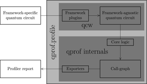
    The overall workflow of qprof is schematically explained in Figure 2. In this workflow, qprof can be seen as a black-box that takes a “quantum circuit” as input and returns a “profiler report”. This black-box view should be enough for users that only want to use the qprof tool, but experienced users or plugins developers might need more details on the internals of qprof in order to understand how it works.
    Fig. 2.
    Fig. 2. Schematic representation of qprof workflow. Internally, qprof uses qcw to recover a framework-agnostic representation of the quantum circuit. Then, this “universal” representation is used to profile the given quantum circuit. Finally, the profiling results are exported using one of qprof exporters and returned to the user.
    The following sections will introduce in details the three different parts that compose qprof. Section 3.2 describes qcw and the framework-agnostic quantum circuit representation it provides and that is used by qprof. A description of the core data structures and core logic is then provided in Section 3.3. Finally, an explanation of the different exporters natively provided by qprof is given in Section 3.4.

    3.2 The qcw Package

    The qprof tool aims at being the standard for profiling quantum circuits, independently of the framework they are written with. In order to be versatile and support as many current and future quantum computing frameworks as possible, qprof uses a package named qcw that is presented in this section.

    3.2.1 The qcw Package.

    qprof extensibility is achieved via a companion Python package called qcw and whose purpose is to abstract away all the specificities of the framework used to represent the quantum circuit and provide a unified interface for all the implemented frameworks. To fulfil its goals of being framework-agnostic and easily extensible, qcw provides a plugin mechanism that allows anyone to implement a wrapper for a specific framework and make it available through the qcw package. This high-extensibility is obtained thanks to the fact that plugins do not have to be part of the main qcw package to be recognised by qcw: they can be developed, used, and published by anyone. This allows several situations that may help improving qcw (and consequently qprof) compatibility with quantum computing framework and extensibility. For example, users might decide to roll-out their own plugin to support a new framework they are using internally. Another important situation that is made possible by qcw and its architecture is that framework vendors have the opportunity to provide a qcw plugin along with their framework and to maintain it as an official plugin, effectively making qprof compatible with their framework without having to support a code base outside of their framework.
    Finally, such an architecture based on an external package that accept plugins allows the user to only install the plugins and frameworks needed instead of installing all of them along with qprof. This simple side improvement greatly reduces the installation time, installation size, and plugin discovery time as it avoids installing and loading unused quantum computing frameworks.

    3.2.2 Framework Support.

    The goal of qcw is to provide a unique interface to access information about quantum programs that can be written using a variety of different frameworks. Taking into account that several of the most successful quantum computing frameworks such as Qiskit, Cirq, PyQuil, or myQLM are Python libraries, and in order to ease its integration with these already existing frameworks, qcw has naturally been designed as a Python library too. It is important to note that this does not impede the capacity of qcw to support non-Python frameworks such as XACC, QCOR, Q#, or Quipper.
    In order to be as generic as possible, qcw uses an abstract common interface to represent the concept of “quantum (sub)routine”. This concept is formally defined in Definitions 13.
    Definition 1.
    Quantum routine: a possibly parameterised, named, sequence of quantum subroutines.
    Definition 2.
    Quantum subroutine: a quantum routine that is part of a higher-level quantum routine (i.e., that is called by another quantum routine).
    Definition 3.
    Native quantum subroutine: a quantum routine that represents a native hardware operation and that does not call any quantum subroutine.
    Using Definitions 13, a common interface for the concept of “quantum routine” emerges. First, a quantum routine should have a name that can be retrieved. Secondly, we should be able to distinguish between native quantum routines and non-native ones. Finally, for each non-native quantum routines, we need a way to iterate over all the subroutines composing it.
    This interface, schematised in Figure 3, is the core abstraction layer of qcw that allows it to be as independent as possible from the underlying quantum computing framework used to represent the profiled quantum circuit and to provide a unified interface across a wide range of different frameworks.
    Fig. 3.
    Fig. 3. Schematic overview of the framework architecture used in qcw. Each framework-specific representation is wrapped by a RoutineWrapper. Each supported framework should have a corresponding qcw plugin that implements the RoutineWrapper interface. The __init__ method initialises a RoutineWrapper instance with an instance of the framework-specific quantum circuit representation. The name method returns the name of the currently wrapped routine. is_base returns True if the routine is a native routine as defined in Definition 3, else it returns False. Finally, the __iter__ method returns an object that can be iterated on and whose iterates are the different subroutines called by the current routine.
    Currently, qcw has been used to successfully access quantum circuits built with the Qiskit and myQLM frameworks. OpenQASM 2.0 support is also implemented using Qiskit translation capabilities by building a qiskit.QuantumCircuit instance from the given OpenQASM 2.0 code and using the Qiskit wrapper of qcw. Using the same idea, an experimental XACC wrapper has been implemented by exporting XACC code to OpenQASM 2.0. Finally, Q# and Quipper support is currently being envisioned and should be implementable as both framework implement either Python bindings or a method to export to OpenQASM 2.0 code.

    3.3 Core Data Structures and Logic

    Now that the issue of adapting qprof to the various quantum computing frameworks has been solved, we can start considering the main problem of profiling a quantum circuit.
    Section 3.3.1 introduces the different quantities that might be interesting to include in a quantum program profiling report, comparing with classical computing quantities when appropriate. Then, Section 3.3.2 explains the main graphical representation used through this article and in qprof: the call-graph representation. Finally, Sections 3.3.3 and 3.3.4 introduce, respectively, the data-structures and the algorithms used internally by qprof to profile a quantum circuit implementation.

    3.3.1 Interesting Data to Profile.

    Profiling a program is the action of gathering data on its execution. For classical programs and profilers, the list of data that can be gathered is quite extensive ranging from high-level quantities such as the time spent in a given function or the memory used during the program execution to low-level information recovered via hardware counters such as cache misses or branch-prediction-misses.
    But for quantum computing, the quantities of interest need to be adapted as several classical data such as cache-miss or branch-prediction-miss do not have any meaning anymore. Nevertheless some classical quantities have a quantum analogue that may be useful for optimisation purposes.
    This is the case for the classical “instruction number” quantity, that translates trivially to its quantum counterpart “native gate number” (or “hardware gate number”). The number of native gates executed by a quantum routine is a useful information for several reasons: it is simple, the routine worst-case execution time can be computed from it, and a lower-bound of the routine error rate can also be devised using this information.
    Another classical quantity that can be translated to quantum computing is the “time spent in routine”. This quantity can be subdivided in two more specific figures: the “time spent exclusively in routine” (sometimes called “self time”) and the “time spent in subroutines called by the routine”. This separation is often done in classical profiling programs as having these two execution times gives very useful information about the profiled routine that cannot be obtained from the “time spent in routine” only.
    The last classical quantity with a meaningful quantum counterpart is the “memory usage”, which may be translated as “number of qubits needed” when using quantum computers.
    About quantities without a clear classical parallel but potentially useful, one can cite the “routine depth” as an approximation of the total execution time of the routine, the “T-count” for error-correction estimates, the “idle time” to estimate the potential effects of qubit decoherence on the routine, the needed “chip topology” in order to execute the routine, the “quantum gate parallelism” the implementation is able to reach, and so on.

    3.3.2 Graph Representation (Call-Graph).

    Following Definitions 13 and the RoutineWrapper interface we defined in Section 3.2.2, a graph-like representation of a quantum program seems to be particularly well suited. In this representation, nodes are quantum routines and an oriented edge from node A to node B means that the quantum routine represented by A calls the quantum subroutine represented by B. This representation of a program is called a call-graph in classical computing.
    Figure 4 shows a call-graph representation of one possible implementation of Grover’s algorithm. Even though this representation is valid according to the general definition of a call-graph, it contains a lot of redundant information that scrambles the useful data in visual noise. Because of this, most of the call graph representations avoid the duplication of nodes, i.e., create one node for a specific routine and re-use this node whenever the routine is called.
    Fig. 4.
    Fig. 4. Call-graph representation of one possible implementation of Grover’s algorithm. Dashed squares with dots within them mean a repetition of the two gates around the dashed node. Dashed arrows starting from the two ccx nodes and the \( C_{n}X \) node represent a sub-graph that has not been included here for readability reasons.
    Figure 5 shows another possible call-graph representation of the same implementation of Grover’s algorithm. Here, a graph node represents a unique routine and is re-used whenever this routine is called.
    Fig. 5.
    Fig. 5. Call-graph representation of one possible implementation of Grover’s algorithm. Each node represents one routine rather than one call to the routine. Edges have been regrouped and labelled with the number of calls for readability purposes. In the internal representation used by qprof, edges are not regrouped and are ordered to account for the original quantum program subroutine call order.

    3.3.3 Data Structures.

    To profile a given quantum circuit (or equivalently a given call-graph), qprof will naturally have to explore it and gather data through the exploration. The exploration is performed using a data structure inspired from graph exploration: RoutineNode.
    A RoutineNode represents one node of the call graph (i.e., one routine of the quantum circuit) and stores information about the represented node. An example of a possible RoutineNode is given in Figure 6.
    Fig. 6.
    Fig. 6. Example of a possible RoutineNode containing information on the cost, the \( T \) -count, and the required topology of the routine it represents. Text on the left of each line represents the name of the stored information and is followed by the type that stores this information. RoutineNode instances always store a (possibly empty) list of subroutines that are called by the represented routine. This list encodes the edges of the call-graph, i.e., if the RoutineNode \( A \) has \( B \) in its subroutines, an edge from \( A \) to \( B \) will be present in the call-graph.
    In order to be as efficient as possible on a wide class of quantum circuits, qprof does its best to reduce the number of call-graph nodes it has to explore. To do so, qprof caches instances of RoutineNode: The first time a routine is seen, its corresponding RoutineNode will be created and saved in order to be re-used without having to re-create the RoutineNode instance each time the routine is encountered.
    This cache mechanism is implemented using a factory pattern: A RoutineNode should only be created indirectly through a dedicated RoutineNodeFactory instance. The RoutineNodeFactory instance keeps track of all the RoutineNode it has already created and implements the cache using Python dict data structure, internally implemented as a hash table. The cache implemented by RoutineNodeFactory has no maximum size, meaning that it will keep each RoutineNode instance created. This absence of cache invalidation is not an issue as every cached routine is already present in the profiled quantum circuit, meaning that qprof memory usage is at worse equivalent to the profiled quantum circuit memory usage.
    Due to the requirements of the hash table data structure, RoutineNode instances should be hashable and comparable with other RoutineNode instances. These requirements are offloaded by qprof to the qcw RoutineWrapper data structure to leave the possibility to use hash and equality operators provided by the wrapped framework. The final interface of the RoutineWrapper data structure is shown in Figure 7.
    Fig. 7.
    Fig. 7. Final RoutineWrapper interface. __init__, name, is_base, and __iter__ methods are described in Figure 3. The __eq__ method tests if other_routine is equal to the current instance. __hash__ computes an integer hash of the currently wrapped routine.
    Note 2.
    The implementation of the hash and equality operators should be performed with care as their characteristics are crucial for qprof runtime and accuracy. The main requirements are imposed by the hash table data structure used by qprof: hash and equality operators should have a complexity in \( \mathcal {O}\left(1 \right) \) , and the hash operator should have the best quality possible (i.e., the lowest collision rate possible).
    Implementing correct hash and equality operations with a complexity of \( \mathcal {O}\left(1 \right) \) may be non-trivial, as the constant complexity requirements prevent the operators from exploring each of the gates contained in the tested routine. qcw implements the hash and equality operators using the name and the parameters of the routine at hand, with the assumption that two routines with the same name and the same parameters will contain exactly the same gates (and consequently, are equal). This assumption might be invalidated in the case of randomised routines.

    3.3.4 qprof Algorithms.

    The main procedure and only function accessible from qprof interface, qprof.profile, is described in Algorithm 1.
    This procedure calls the method RoutineNodeFactory.get that is detailed in Algorithm 2. A study of the runtime complexity of Algorithm 2 is provided in Section 4.1.
    Algorithms used by the different exporters to summarise the call-graph built with RoutineNode instances may use internal data structures and other algorithms in order to generate a report. These are specific to the exporter and Section 3.4.1 gives an example with some details and a description of the data structure used by the gprof-compatible exporter along with the limitation it imposes to the quantum circuits that can be handled by the exporter.

    3.4 Exporters

    qprof also implement several exporters that will transform the abstract quantum program representation described in Sections 3.3.2 and 3.3.3 to a more usable format.
    Exporters should implement a specific interface schematised in Figure 8. qprof natively implements two textual exporters: one that outputs a gprof-compatible format and another that returns a JSON-formatted string that directly represents a flat call-tree structure used internally by the gprof exporter.
    Fig. 8.
    Fig. 8. Exporter interface. Any plugin that implements an exporter should be a derived from the BaseExporter class and implement this interface. The return type of the export method is not specified and can be anything. The main profile function will return the output of the exporter.

    3.4.1 Flat Call-Tree Representation.

    Before the profiler report generation, it is convenient to summarise the information contained in the generic call-graph structure presented in Sections 3.3.2 and 3.3.3. To do so, the gprof and JSON exporters both rely on a flat structure that represents a directed call-tree (i.e., a directed call-graph without loops).
    This structure puts an additional restriction to the quantum programs that can be profiled using these exporters: the interdiction to have recursive subroutines (a subroutine that ends up calling itself). It is important to realise that this restriction does not have a huge impact on the area of application of qprof because, as of today, recursive subroutine calls do not seem to be widespread in quantum computing programs and the restriction only applies to the gprof and JSON exporters, the core logic of qprof being capable of handling recursive subroutine calls without any issue.
    The flat call-tree structure stores, for each subroutine A encountered in the call-graph exploration, a list of all the subroutines B called by A. Along with each called subroutine B, the structure stores the number of times B has been called by A and the cost associated with these calls. Finally, in order to simplify the report generation, each called routine B will also store a list of the routines A it has been called by. Within this list is also stored the number of calls to B that have been performed from each A and the cost associated with these calls.

    3.4.2 gprof Output.

    The gprof exporter aims at generating a profiler report that is compatible with the profiler report returned by gprof, a well-known classical profiler. Being compatible with a tool that has been around for decades and is still actively used has several advantages.
    First and foremost, the fact that a tool that has been stable for decades and is still actively used shows that it provides satisfaction to its users, meaning that the output format includes enough information and is sufficiently easy to read and use in practice.
    Secondly, a decades-old, largely used, output format is likely to have a lot of official or user-contributed tools to help analysing and representing it in the best way possible. This is the case for the gprof format that can be translated to a call-graph using the gprof2dot tool and the dot executable from Graphviz library.
    Finally, the gprof output is simple to generate: It is a textual file with a simple and regular format.

    3.4.3 Reading a gprof-Based Call-Graph.

    As explained in Section 3.4.2, gprof output (and qprof output when used with the gprof-compatible exporter) can be visualised as a call-graph using the gprof2dot tool and the dot executable from the Graphviz library. Such a call-graph is depicted in Figure 9.
    Fig. 9.
    Fig. 9. Example of a simple call-graph generated with the help of gprof2dot and the dot tool from the Graphviz library.
    Each node of the graph represents a unique quantum routine. The name of this quantum routine can be read on the first line of text inside the node. The second line of text in the node is the percentage of the total cost associated with the routine represented by the node, including the cost of subroutines called by the routine (also called total_time when the considered cost is the execution time). The third line represents the total cost of the routine represented by the node, but excluding subroutines (also called self_time when the considered cost is the execution time). The fourth line represents the number of times the routine is called in the program. Finally, each node is coloured according to the total time spent in the routine it represents from dark-red for high-cost routines to light-green for low-cost routines.
    Each directed edge of the graph represents a subroutine call: If a directed edge that goes from node parent to node child is present, it means that the routine represented by node parent is calling the subroutine represented by node child at least once. Each edge is annotated with the percentage of the total cost transferred from parent to child (i.e., the cost that was consumed calling child from within parent) and the number of times parent is calling child.
    With these definitions, and provided that the cost used is an additive quantity, the main routine will always have an execution time of \( 100\% \) and the sum of the percentages of each outgoing edge of a given node should be equal to the total_time of this node.

    3.4.4 Advantages of the Call-Graph Visualisation.

    There are several advantages to the call-graph representation used in Figure 9 when compared to the other possible representations of a quantum circuit.
    One of the most widespread way of representing a quantum circuit in the quantum computing community is depicted in Figure 10. This representation has the advantage of being simple to understand and precise with respect to which quantum operation should be applied and when. One of the disadvantages of this representation is that it becomes quickly unreadable for quantum circuits containing a lot of quantum gates. It is also a shallow representation: The only way of representing a main quantum circuit \( C \) that calls the subroutine \( R \) without inlining the call to \( R \) in \( C \) is by representing \( C \) and \( R \) separately. This becomes quickly unmanageable for complex quantum circuits that may call tens of nested subroutines.
    Fig. 10.
    Fig. 10. Standard representation of a quantum circuit. Time goes from left to right, giving the order in which quantum gates are applied. Horizontal lines represent qubits. Gates are represented by rectangles, with the notable exception of the CNOT gates that has a control qubit (small black dot) and a target qubit (circle with a cross in the inside) linked together by a straight line.
    The call-graph representation has the advantage of complementing the standard quantum circuit representation of Figure 10: Its main strength is its ability to represent very large and deeply nested quantum circuits in one synthetic and concise graph, providing a readable and global representation of the whole quantum circuit. In the call-graph representation, all the routines of the profiled quantum circuit are represented and the relationship between each routine (which one calls and which one is called) is explicit.

    4 Complexity and Runtime Analysis

    4.1 Asymptotic Complexity of qprof

    The runtime efficiency of qprof is one of its strength: It will be very efficient on most of real-world quantum circuit implementation.
    Let first recall that qprof only access a quantum circuit through the interface provided by qcw and summarised in Figure 7. This means that computing the asymptotic complexity of profiling a given quantum circuit depends on the complexity of the qcw methods and on the number of call to such methods qprof needs to perform.
    Algorithm 2 details the algorithm used by qprof to initialise its internal data structures. This algorithm is only applied once, on the routine to profile (the call-graph root, i.e., the only node that does not have any incoming edge), and then recurses into the call graph to explore all the nodes needed.
    qcw interface is implicitly or explicitly called on six lines of Algorithm 2. First on lines 1 and 2, the hash and equality operators are called in order to perform hash table operations. Then, on line 8, the name of the currently explored routine is retrieved once. A test to check if the routine is considered as “native” is performed with a call to the is_base method at line 9. The for-loop on line 13 is also calling the __iter__ method once. Finally, line 18 is calling the hash and equality operators again to add an entry in the cache implemented as a hash table.
    Note 3.
    The __iter__ method is only called once but will iterate over all the subroutines of the current routine even those that have already been seen and cached by qprof. The already cached subroutines will simply end the recursion for this branch of the call-graph in the call to factory.get without exploring their subroutines.
    A summary of the number of calls to the different methods provided by qcw interface is provided in Table 1.
    Table 1.
    RoutineWrapper methodLeafs, non-cachedNon-leafs, non-cachedNodes, cached
    name () -> str110
    is_base () -> bool110
    __iter__() -> iterator01 (see Note 3)0
    __eq__(other) -> boolc2cc
    __hash__() -> int121
    Table 1. Number of Calls of qprof Implementation to the qcw Interface for Each Explored Node of the Call-Graph
    Note that a few optimisations that do not appear on Algorithm 2 for readability purpose have been performed in the implementation. This table provides the counts of the optimised implementation. \( c \) is a number that depends on the implementation of the hash table and the quality of the hash function used and that represents the expected average number of equality tests that should be performed at each access to the hash table. “Nodes” in the last column encompass both “Leafs” and “Non-leafs”.
    Even though \( c \) in Table 1, the average number of calls to __eq__, seems hard to bound in general, Python documentation provides guarantees on the asymptotic complexity of the operations on a dict instance: access and modification of the data structure, which are the two operations performed by qprof, are \( \mathcal {O}\left(1 \right) \) on average and \( \mathcal {O}\left(n \right) \) on amortised worst case. This means that for each explored nodes of the call-graph, qprof will only have to perform \( \mathcal {O}\left(1 \right) \) operations on average.
    In the end, qprof asymptotic complexity depends entirely on the number of nodes of the call-graph it needs to explore. This number depends on the profiled circuit and no general formula that include the number of gates in the profiled quantum circuit can be devised.
    To illustrate this claim, two example quantum circuits are provided. Figure 11 provides an example of a quantum circuit that contains only 1 quantum gate but that will require qprof to visit an arbitrarily large number \( N \) of nodes in the call-graph. On the other side, Figure 12 shows a quantum circuit that contains \( N = 2^n \) quantum gates but that will only require qprof to explore \( \mathcal {O}\left(\log _2 N \right) \) nodes of the call-graph.
    Fig. 11.
    Fig. 11. Example of quantum circuit that contains a constant number of quantum gates (here only 1) but that will require qprof \( \mathcal {O}\left(n \right) \) operations to analyse and output a profile report.
    Fig. 12.
    Fig. 12. Example of quantum circuit that contains an exponential number of quantum gates (here \( 2^n \) ) but that will require qprof only \( \mathcal {O}\left(n \right) \) operations to analyse and output a profile report.
    We can still have an upper-bound of the number of operations qprof will have to perform on a given quantum circuit by restricting each routine to call at most \( N_{\mathrm{subroutine}} \) subroutines and by using the number of unique quantum gates \( N_u \) used in the circuit. For example, the quantum circuit depicted in Figure 12(b) has \( N_u = 4 \) because it contains four unique gates: \( \lbrace H, 2, 3, 4\rbrace \) and the quantum circuit depicted in Figure 11(b) has \( N_u = n \) unique quantum gates: \( \lbrace H, 2, \dots {}, n-1, n\rbrace \) . For a quantum circuit in which routines are restricted to call at most \( N_{\mathrm{subroutine}} \) subroutines, qprof will explore at most \( \left(N_{\mathrm{subroutine}} \times {} N_u\right) \) nodes of the call-graph.

    4.2 Real-World Execution Time

    We benchmarked the execution time of qprof on several well-known use-cases. These benchmarks were performed on one core of a Intel Xeon Platinum 8260M cadenced at 2.40 GHz. Tables 24 give the average and standard deviation of the profiling time for quantum circuits implementing three different use-cases. The “Profiling time” and “Saved time” measurements have been performed 100 times and each table contains the average time and the standard deviation observed over the 100 executions.
    Table 2.
    N# QubitGate numberGeneration (s)Profiling time (s)Saved time (s)
    \( 2^3 \) 41268460.0000.01 \( \pm \) 0.000.82 \( \pm \) 0.01
    \( 2^4 \) 55287680.0000.02 \( \pm \) 0.002.99 \( \pm \) 0.03
    \( 2^5 \) 619537200.0000.04 \( \pm \) 0.0110.17 \( \pm \) 0.14
    \( 2^6 \) 767738680.0000.09 \( \pm \) 0.0233.26 \( \pm \) 0.31
    \( 2^7 \) 8225756720.0000.24 \( \pm \) 0.03106.92 \( \pm \) 1.52
    \( 2^8 \) 9733237920.0000.66 \( \pm \) 0.03333.43 \( \pm \) 4.26
    \( 2^9 \) 102338165440.0001.90 \( \pm \) 0.041043.10 \( \pm \) 14.02
    \( 2^{10} \) 117354735200.0005.48 \( \pm \) 0.073215.83 \( \pm \) 44.62
    \( 2^{11} \) 1222890288960.00015.73 \( \pm \) 0.159914.92 \( \pm \) 132.58
    \( 2^{12} \) 1370635259440.00045.77 \( \pm \) 0.4230473 \( \pm \) 275
    \( 2^{13} \) 14216432314280.000132.21 \( \pm \) 1.1592083 \( \pm \) 1133
    \( 2^{14} \) 15659220508800.000383.65 \( \pm \) 6.79270824 \( \pm \) 5494
    Table 2. qprof Observed Runtime on Quantum Circuits Generated Using the Quantum Program Described in [35] and Also Used in Listing 3
    The evolve_1d_dirichlet function was used with an evolution time of 0.1, a desired precision \( \epsilon = 10^{-3} \) , a trotter order of 1, and a varying number of discretisation points given in the \( N \) column. The nearly instantaneous generation times have to do with how the myQLM framework is working: The circuit is generated lazily when needed. Consequently, the Profiling time and Saved time columns also include the time needed to construct the quantum circuits. Profiling time and Saved time columns provide \( \mathtt {average} \pm \mathtt {standard\_deviation} \) numbers obtained by profiling 100 times the generated circuit.
    Table 3.
    N# QubitGate numberGeneration (s)Profiling time (s)Saved time (s)
    \( 2^1 \) 510490.0870.02 \( \pm \) 0.010.06 \( \pm \) 0.05
    \( 2^2 \) 987590.4650.03 \( \pm \) 0.000.19 \( \pm \) 0.00
    \( 2^3 \) 13348661.5230.09 \( \pm \) 0.020.45 \( \pm \) 0.03
    \( 2^4 \) 161921047.5720.18 \( \pm \) 0.001.56 \( \pm \) 0.01
    \( 2^5 \) 2058117021.8810.63 \( \pm \) 0.094.14 \( \pm \) 0.33
    \( 2^6 \) 24174422563.6122.09 \( \pm \) 0.2511.63 \( \pm \) 0.79
    \( 2^7 \) 284937772175.5467.23 \( \pm \) 0.8931.41 \( \pm \) 1.09
    \( 2^8 \) 3212310383441.94925.67 \( \pm \) 0.7391.72 \( \pm \) 3.58
    \( 2^9 \) 36334717471234.26398.59 \( \pm \) 0.12289.60 \( \pm \) 3.76
    Table 3. qprof Observed Runtime on Quantum Circuits Generated Using the Function qiskit.algorithms.HHL
    The linear system matrices were constructed with the function qiskit.algorithms.linear_ solvers.matrices.TridiagonalToeplitz( \( N \) , 1, 0.5) and the right-hand side \( b \) has been picked randomly. Profiling time and Saved time columns provide \( \mathtt {average} \pm \mathtt {standard\_deviation} \) numbers obtained by profiling 100 times the generated circuit.
    Table 4.
    N# QubitGate numberGeneration (s)Profiling time (s)Saved time (s)
    1518350492.6440.07 \( \pm \) 0.000.44 \( \pm \) 0.00
    773021665111.8400.21 \( \pm \) 0.032.15 \( \pm \) 0.45
    2213434081717.4600.26 \( \pm \) 0.002.96 \( \pm \) 0.02
    4373851103924.1610.30 \( \pm \) 0.003.84 \( \pm \) 0.04
    8994273730134.1970.36 \( \pm \) 0.004.89 \( \pm \) 0.06
    202146103054742.2040.44 \( \pm \) 0.006.69 \( \pm \) 0.07
    408750140268158.8690.51 \( \pm \) 0.018.50 \( \pm \) 0.10
    655754186656776.8880.59 \( \pm \) 0.1610.03 \( \pm \) 1.31
    1435158243602998.2850.62 \( \pm \) 0.0111.29 \( \pm \) 0.14
    30967623125851109.1530.73 \( \pm \) 0.0114.47 \( \pm \) 0.12
    38021663951777142.0070.81 \( \pm \) 0.0116.85 \( \pm \) 0.20
    Table 4. qprof Observed Runtime on Quantum Circuits Generated Using the Function qiskit.algorithms.Shor Trying to Factor the Number \( N \)
    Profiling time and Saved time columns provide \( \mathtt {average} \pm \mathtt {standard\_deviation} \) numbers obtained by profiling 100 times the generated circuit.
    “Saved time” is an estimation of the execution time saved thanks to the caching mechanism implemented. It is computed by saving the time needed to profile a routine when it is first encountered and then incrementing a counter by this exact same time each time the routine is seen again and the cache is used. This methodology tends to produce noisy results because an imprecision in the first measurement will lead to an accumulation of errors, but the computed standard deviations are always relatively low compared to the average which is a good indicator that the obtained “Saved time” is close to the real saved time.

    5 Code Examples and Practical Applications

    This section includes several examples of qprof usage on various quantum circuits ranging from a simple Toffoli gate decomposition in Section 5.1 to more complex algorithm implementations such as Grover’s algorithm in Section 5.2. All these benchmarks are performed on circuits generated using the qiskit framework. An example of benchmarking a quantum implementation of a 1-dimensional wave equation solver written using the myQLM framework is finally provided in Section 5.3.

    5.1 Benchmarking a Simple Program

    One of the most simple quantum program that can be benchmarked is the implementation of a Toffoli gate. Such a benchmark has the benefit of being simple enough to be studied by hand which means that we will be able to verify qprof results by hand-computing them.
    The decomposition of a Toffoli gate as implemented in the qiskit framework is depicted in Figure 13. A complete example using qprof to profile the default Toffoli gate decomposition in qiskit is shown in Listing 1.
    Fig. 13.
    Fig. 13. Standard decomposition of a Toffoli gate into \( 1- \) and \( 2- \) qubit gates.
    Code Listing 1.
    Code Listing 1. Python code needed to use qprof on the Toffoli gate implementation and save the profiler report in a gprof-compatible format in a file named toffoli.qprof.
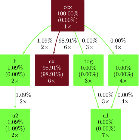
    The output of qprof, which is here in a gprof-compatible format, can then be analysed. For the sake of readability and brevity, the full gprof-compatible profiler report will not be included verbatim in this article and will rather be visualised using the gprof2dot tool that allows representing gprof reports as call-graphs. The call-graph obtained from the report generated in Listing 1 is depicted in Figure 14.
    Fig. 14.
    Fig. 14. Call-graph for the Toffoli gate implementation. Quantum gates included in the gate_costs variable (here u, u1, u2, u3, and cx) are considered as native gates. Only native gates have a non-zero self-time as they are the only gates that are really executed on the hardware.
    From the call-graph depicted in Figure 14, it is clear that the cost of a Toffoli gate comes from its six controlled- \( X \) gates, that account for more than \( 98\% \) of the total execution time. It is also interesting to note that the \( T \) gate, known to be very costly when error-correction is needed, is “free” on IBM Quantum chips when error-correction is not needed as it is equivalent to a phase change.

    5.2 Grover’s Algorithm

    The Toffoli gate is a good example to start and understand the meaning of qprof’s output but the end goal of qprof is to be able to profile large and complex quantum circuits. A good first candidate to show how qprof performs on a more complex circuit is Grover’s algorithm.
    In this example, we use Grover’s algorithm on four qubits to find the three quantum states that verify the following formula:
    \( \begin{equation} (q_0 \vee \lnot q_1) \wedge (\lnot q_2 \wedge q_3). \end{equation} \)
    (1)
    The only three 4-qubit quantum states verifying Equation (1) are \( \vert 0001 \rangle \) , \( \vert 1001 \rangle \) , and \( \vert 1101 \rangle \) , \( q_0 \) being the left-most qubit in the bra-ket notation.
    The code needed to generate the gprof-compatible output for Grover’s algorithm with the oracle presented in Equation (1) is given in Listing 2. The resulting call-graph, included in Figure 15, clearly shows that the controlled- \( X \) gate is still the major contributor to the total cost. But this time, contrarily to the Toffoli example shown in Section 5.1, the controlled- \( X \) gate is called by three different subroutines that all contribute significantly to the overall cost: c3z, ccz, and mcx.
    Fig. 15.
    Fig. 15. Call-graph for the Grover’s algorithm implementation. Quantum gates included in the gate_costs variable (here u, u1, u2, u3, and cx) are considered as native gates. Only native gates have a non-zero self-time as they are the only gates that are really executed on the hardware. Some percentages might not add up to exactly \( 100\% \) due to rounding errors.
    Thanks to qprof, it is now easy to understand the subroutines that contribute the most to the total cost. More importantly, the gprof-compatible report and the call-graph representation give very insightful information about subroutines calls that are crucial for circuit optimisation. Such information can be used to weight the impact of a given optimisation and then decide whether or not it is worth applying it.
    For example, knowing that the ccz subroutine takes \( 18.61\% \) of the total time, it is easy to deduce that a \( 20\% \) improvement in the implementation of ccz will translate into a tiny \( \frac{18.61\%}{5} = 3.72\% \) improvement to the overall cost, which might not be worth the effort. On the other hand, optimising the c3z subroutine to reduce its cost by \( 20\% \) improves the overall cost by \( 9.22\% \) , which is nearly \( 10\% \) and might be an interesting optimisation target. Finally, the call-graph visualisation conveys clearly the information that the cx gate is the most costly subroutine of the Grover’s circuit, meaning that even a slight optimisation of the cx cost will have a high impact on the overall implementation cost.
    Code Listing 2.
    Code Listing 2. Python code needed to use qprof on the Grover implementation and save the profiler report in a gprof-compatible format in a file named grover.qprof.

    5.3 Quantum Wave Equation Solver

    Finally, we include in this article a more complex example that has been implemented in a previous work with myQLM, a quantum computing framework maintained by Atos. The code used to generate the benchmarked quantum program is available at https://gitlab.com/cerfacs/qaths/ and is explained in [35].
    Code Listing 3.
    Code Listing 3. Python code needed to use qprof with the QatHS library, on top of myQLM, and save the profiler report in a gprof-compatible format in a file named qaths.qprof.
    This example demonstrates that, as can be seen in Listing 3, qprof interface stays nearly the same even though the framework used is now completely different. The only exceptions are some additional parameters (such as linking_set in Listing 3) that are directly forwarded to the framework plugin used and additional gate definitions in the gate_costs data structure because of the way gate decomposition is handled in myQLM.
    The call graph obtained by running Listing 3 is reproduced in Figure 16. In order for the call-graph to be readable on a paper format, negligible subroutines and calls (i.e., nodes and edges, respectively) have been discarded from the graphical representation. The call-graph clearly shows that most of the execution time is spent in the oracle implementation. Moreover, multi-controlled- \( X \) gates are the major contributors to the total execution time.
    Fig. 16.
    Fig. 16. Call-graph of the quantum wave equation solver. Nodes (i.e., quantum routines) that account for less than \( 0.5\% \) of the total execution time are not plotted. Edges (i.e., subroutine calls) that account for \( 0.1\% \) or less of the total execution time are also discarded for readability purposes.

    6 Discussion

    Now that we have described qprof internals and how to use it on quantum circuits, we can compare the insights it provides with the current state-of-the-art. We also discuss the current limitations of the tool and potential improvements that could be added in the future.

    6.1 Comparison with the State-of-the-Art

    A description of the profiling or resource estimate capabilities of several widely used quantum computing frameworks have been provided in Section 2.2.
    One of the first advantages provided by qprof comparatively with the frameworks presented in Section 2.2 is its framework agnostic interface. As explained in Section 3.2 and shown in Listing 1 to 3, qprof can handle nearly transparently different quantum computing frameworks and provide a standardised report. The fact that qprof has been architectured as shown in Figure 2 allows it to decouple entirely the framework used to represent the profiled quantum circuit from the output format. It means that if a new exporter is implemented in the future, it will be available for all the implemented frameworks. Conversely, if a new framework adapter is added to qcw, qprof will directly be able to generate reports using all the already existing exporters. This decoupling, crucial due to the increasing number of quantum computing frameworks, has not been implemented by any of the existing resource estimation features listed in Section 2.2, each framework providing features that are only compatible with its own quantum circuit representation.
    Additionally qprof already provides a more detailed report than most of the quantum computing frameworks listed in Section 2.2. The Q# Flame graph exporter provides the same type of information by using a different visualisation format (Flame graphs [20]) but seems to be less flexible than qprof with respect to the quantities that can be profiled.

    6.2 qprof and Quantum Circuit Compilation

    qprof might be used to understand the impact of quantum compilation on a given quantum circuit provided that the compilation tool-chain used does not destroy the call-graph structure of the quantum circuit.
    One of the only strong requirement of the qprof tool is that the quantum circuit provided can be explored using the unified interface provided by qcw. But in order for qprof to generate a useful report, a few other requirements should be checked.
    First, routine names should be informative and human-readable. This requirement seems trivial at first sight, but quantum program compilers might generate routines, for example, using quantum circuit synthesis algorithms [10, 30, 38], and the name attached to the generated quantum circuit might not be informative at all.
    Secondly, and even more importantly, the profiled quantum program should contain enough information about the routines and subroutines used. Some compilers such as the one used by Qiskit at the time of writing (version 0.32.1) start the compilation process by flattening the quantum circuit and unrolling all the quantum gates that are not in the basis provided. As soon as the quantum circuit has been flattened, all the call-graph information is lost and cannot be retrieved by qprof anymore, making its report less useful when the profiled circuit has been flattened.
    Figure 17 illustrates this issue with an implementation of Shor’s algorithm trying to factorise the number 15: qprof report before the transpilation provides enough information to plot a meaningful call-graph as shown in Figure 17(a) whereas qprof report for the exact same circuit but after calling Qiskit transpiler (Figure 17(b)) contains nearly no useful information.
    Fig. 17.
    Fig. 17. Effect of using Qiskit transpiler on qprof reports. Using Qiskit transpiler flattens the quantum circuit and effectively replace every routine call that is not in the transpilation basis by equivalent calls to gates in the transpilation basis, making qprof report less informative and useful. Note that Qiskit transpiler inserted \( CX \) gates in order to make the quantum circuit compliant with ibm_cairo topology, which is why the gate cost of the cx gate became even more predominant in the transpiled circuit.
    This means that qprof will only interact nicely with compilers if and only if the compiler used is able to keep relatively untouched the structure of the call-graph. Currently, only a few compilers are able to do so but projects like QCOR [27] may help democratising this approach. For compilers that check this property, qprof will be able to help visualising the effect of compiler on the circuit costs by plotting the call-graphs of the original and compiled circuits side by side and comparing the different costs computed.

    6.3 qprof and Hardware-Aware Timings

    The fact that most of the current compilers are flattening the compiled circuit makes qprof reports less meaningful and informative as shown in Section 6.2. Not being able to use compilers restrict the class of quantum circuits that might be sent to qprof: hardware-compliant circuits are not likely to be analysed for the moment. This is due to the fact that to get an hardware compliant circuit, one should either use a compiler, which is not possible yet as discussed earlier, or build a hardware-compliant circuit directly, which is an exceedingly complex task for large circuits.
    Because hardware-compliant circuits are, for the moment, unlikely to be studied with qprof, the tool is not yet capable of adapting the costs of a given gate depending on the qubits it is applied on.

    6.4 Limitations of the gprof Exporter

    The main output format for qprof reports are based on the output format of gprof [13, 19] for several reasons: standard format, widely used during decades, human-readable, availability of external tools to get visual representations from the textual format, and so on. But this output format is inherently limited to sequential programs, which impose a strong limitation on what it can represent. When exporting using the gprof-based format, qprof will not take into account gate parallelism, i.e., as if quantum gates were executed sequentially, one at a time. Trying to take into account gate parallelism using the gprof-based format leads to percentages not adding up to \( 100\% \) which was deemed too confusing to be worth implementing.

    6.5 qprof and NISQ Circuits

    qprof is currently only using a limited set of information on the profiled quantum routines. In particular, even though the information is available through qcw for some frameworks, qprof ignores on which qubits a particular routine is applied on for the moment.
    By extending qcw public interface in Figure 7 to include a way to access qubits the routine is applied on and modifying slightly Algorithm 2 (see comment above line 16) to allow non-additive quantities to be profiled, qprof would be able to include gate error or topology in its profiles.
    The gate error estimation would be a nice addition for NISQ algorithms, even though only providing a lower bound on the real error that would be observed on hardware due to the presence of other source of errors such a decoherence, cross-talk, or “SPAM” (state preparation and measurement) errors.
    Reporting on topology has its own challenges, one of them being to find a good format for qprof report as the gprof format is not adapted to include such information.

    6.6 qprof and Dynamical Circuits

    qprof being a static analyser, it does not support dynamical circuits that may use the result of a previous quantum operation to determine which is the next quantum gate to execute. Moreover, the features related to dynamic circuits are still not introduced in a lot of quantum computing frameworks and, for the frameworks that do implement some of them, are relatively new. As such, the companion package qcw and the unique interface it provides has not been updated to include information about dynamic circuits.

    7 Conclusion

    In this article, we introduced qprof, an open-source and, to the best of our knowledge, novel tool that is able to generate profiling reports in well-known formats from a quantum circuit implementation. Our library is able to natively read quantum circuits from multiple frameworks—currently Qiskit, myQLM, OpenQASM 2.0, and XACC—and can be easily extended to support more quantum computing libraries. It generates consistent reports independently of the underlying framework used. qprof opens new optimisation opportunities for quantum scientists and programmers by allowing them to view their quantum circuit implementation in a well-known, synthetic, and visual representation.
    In this article, we presented the main concepts used in the internals of qprof: how is qprof able to be framework-agnostic thanks to a unique interface provided by qcw, the processing performed by qprof in order to compute quantities of interest to profile and how exporters are used to output the profiling report in a usable and convenient format. We then analysed qprof runtime performance by providing asymptotic complexity estimates, examples of worst- and best-case quantum circuits, and benchmarked execution times on several well-known quantum circuit implementations. We also used qprof on three different quantum circuit implementations of increasing complexity to demonstrate its features: simplicity of use, adaptability and consistency of the interface, and generated reports.
    Finally, we discussed potential improvements and limitations of qprof, opening the way for more development on the tool. In the future, we plan to extend the set of supported quantum computing frameworks. The number of exporters can also be improved to handle different output formats such as a perf_event [14] compatible format or a Flame graph [20] compatible one, allowing to easily use new visualisations such as Flame graphs [20].

    Supplementary Material

    The qprof tool is available at https://gitlab.com/qcomputing/qprof/qprof. The different qcw packages are available at https://gitlab.com/qcomputing/qcw.

    Acknowledgments

    The authors would like to thank Siyuan Niu for proofreading early versions of this article.

    References

    [1]
    Scott Aaronson and Daniel Gottesman. 2004. Improved simulation of stabilizer circuits. Physical Review A 70, 5 (Nov. 2004), 052328. DOI:
    [2]
    Héctor Abraham, AduOffei, Rochisha Agarwal, Ismail Yunus Akhalwaya, Gadi Aleksandrowicz, Thomas Alexander, Matthew Amy, Eli Arbel, Arijit02, Abraham Asfaw, Artur Avkhadiev, Carlos Azaustre, Aziz Ngoueya, Abhik Banerjee, Aman Bansal, Panagiotis Barkoutsos, Ashish Barnawal, George Barron, George S. Barron, Luciano Bello, Yael Ben-Haim, Daniel Bevenius, Arjun Bhobe, Lev S. Bishop, Carsten Blank, Sorin Bolos, Samuel Bosch, Brandon, Sergey Bravyi, Bryce-Fuller, David Bucher, Artemiy Burov, Fran Cabrera, Padraic Calpin, Lauren Capelluto, Jorge Carballo, Ginés Carrascal, Adrian Chen, Chun-Fu Chen, Edward Chen, Jielun (Chris) Chen, Richard Chen, Jerry M. Chow, Spencer Churchill, Christian Claus, Christian Clauss, Romilly Cocking, Filipe Correa, Abigail J. Cross, Andrew W. Cross, Simon Cross, Juan Cruz-Benito, Chris Culver, Antonio D. Córcoles-Gonzales, Sean Dague, Tareq El Dandachi, Marcus Daniels, Matthieu Dartiailh, DavideFrr, Abdón Rodríguez Davila, Anton Dekusar, Delton Ding, Jun Doi, Eric Drechsler, Drew, Eugene Dumitrescu, Karel Dumon, Ivan Duran, Kareem EL-Safty, Eric Eastman, Grant Eberle, Pieter Eendebak, Daniel Egger, Mark Everitt, Paco Martín Fernández, Axel Hernández Ferrera, Romain Fouilland, Franck Chevallier, Albert Frisch, Andreas Fuhrer, Bryce Fuller, Melvin George, Julien Gacon, Borja Godoy Gago, Claudio Gambella, Jay M. Gambetta, Adhisha Gammanpila, Luis Garcia, Tanya Garg, Shelly Garion, Austin Gilliam, Aditya Giridharan, Juan Gomez-Mosquera, Gonzalo, Salvador de la Puente González, Jesse Gorzinski, Ian Gould, Donny Greenberg, Dmitry Grinko, Wen Guan, John A. Gunnels, Mikael Haglund, Isabel Haide, Ikko Hamamura, Omar Costa Hamido, Frank Harkins, Vojtech Havlicek, Joe Hellmers, Łukasz Herok, Stefan Hillmich, Hiroshi Horii, Connor Howington, Shaohan Hu, Wei Hu, Junye Huang, Rolf Huisman, Haruki Imai, Takashi Imamichi, Kazuaki Ishizaki, Raban Iten, Toshinari Itoko, JamesSeaward, Ali Javadi, Ali Javadi-Abhari, Wahaj Javed, Jessica, Madhav Jivrajani, Kiran Johns, Scott Johnstun, Jonathan-Shoemaker, Vismai K., Tal Kachmann, Akshay Kale, Naoki Kanazawa, Kang-Bae, Anton Karazeev, Paul Kassebaum, Josh Kelso, Spencer King, Knabberjoe, Yuri Kobayashi, Arseny Kovyrshin, Rajiv Krishnakumar, Vivek Krishnan, Kevin Krsulich, Prasad Kumkar, Gawel Kus, Ryan LaRose, Enrique Lacal, Raphaël Lambert, John Lapeyre, Joe Latone, Scott Lawrence, Christina Lee, Gushu Li, Dennis Liu, Peng Liu, Yunho Maeng, Kahan Majmudar, Aleksei Malyshev, Joshua Manela, Jakub Marecek, Manoel Marques, Dmitri Maslov, Dolph Mathews, Atsushi Matsuo, Douglas T. McClure, Cameron McGarry, David McKay, Dan McPherson, Srujan Meesala, Thomas Metcalfe, Martin Mevissen, Andrew Meyer, Antonio Mezzacapo, Rohit Midha, Zlatko Minev, Abby Mitchell, Nikolaj Moll, Jhon Montanez, Gabriel Monteiro, Michael Duane Mooring, Renier Morales, Niall Moran, Mario Motta, MrF, Prakash Murali, Jan Müggenburg, David Nadlinger, Ken Nakanishi, Giacomo Nannicini, Paul Nation, Edwin Navarro, Yehuda Naveh, Scott Wyman Neagle, Patrick Neuweiler, Johan Nicander, Pradeep Niroula, Hassi Norlen, NuoWenLei, Lee James O’Riordan, Oluwatobi Ogunbayo, Pauline Ollitrault, Raul Otaolea, Steven Oud, Dan Padilha, Hanhee Paik, Soham Pal, Yuchen Pang, Vincent R. Pascuzzi, Simone Perriello, Anna Phan, Francesco Piro, Marco Pistoia, Christophe Piveteau, Pierre Pocreau, Alejandro Pozas-Kerstjens, Milos Prokop, Viktor Prutyanov, Daniel Puzzuoli, Jesús Pérez, Quintiii, Rafey Iqbal Rahman, Arun Raja, Nipun Ramagiri, Anirudh Rao, Rudy Raymond, Rafael Martín-Cuevas Redondo, Max Reuter, Julia Rice, Matt Riedemann, Marcello La Rocca, Diego M. Rodríguez, RohithKarur, Max Rossmannek, Mingi Ryu, Tharrmashastha SAPV, SamFerracin, Martin Sandberg, Hirmay Sandesara, Ritvik Sapra, Hayk Sargsyan, Aniruddha Sarkar, Ninad Sathaye, Bruno Schmitt, Chris Schnabel, Zachary Schoenfeld, Travis L. Scholten, Eddie Schoute, Joachim Schwarm, Ismael Faro Sertage, Kanav Setia, Nathan Shammah, Yunong Shi, Adenilton Silva, Andrea Simonetto, Nick Singstock, Yukio Siraichi, Iskandar Sitdikov, Seyon Sivarajah, Magnus Berg Sletfjerding, John A. Smolin, Mathias Soeken, Igor Olegovich Sokolov, Igor Sokolov, SooluThomas, Starfish, Dominik Steenken, Matt Stypulkoski, Shaojun Sun, Kevin J. Sung, Hitomi Takahashi, Tanvesh Takawale, Ivano Tavernelli, Charles Taylor, Pete Taylour, Soolu Thomas, Mathieu Tillet, Maddy Tod, Miroslav Tomasik, Enrique de la Torre, Kenso Trabing, Matthew Treinish, TrishaPe, Davindra Tulsi, Wes Turner, Yotam Vaknin, Carmen Recio Valcarce, Francois Varchon, Almudena Carrera Vazquez, Victor Villar, Desiree Vogt-Lee, Christophe Vuillot, James Weaver, Johannes Weidenfeller, Rafal Wieczorek, Jonathan A. Wildstrom, Erick Winston, Jack J. Woehr, Stefan Woerner, Ryan Woo, Christopher J. Wood, Ryan Wood, Stephen Wood, Steve Wood, James Wootton, Daniyar Yeralin, David Yonge-Mallo, Richard Young, Jessie Yu, Christopher Zachow, Laura Zdanski, Helena Zhang, Christa Zoufal, Zoufalc, A. Kapila, A. Matsuo, bcamorrison, brandhsn, Nick Bronn, B. Rosand, chlorophyll zz, csseifms, Dekel Meirom, Dekel Meirom, dekool, dime10, drholmie, D. Trenev, ehchen, elfrocampeador, Faisal Debouni, fanizzamarco, gabrieleagl, gadial, galeinston, Georgios T. S., gruu, H. Horii, hykavitha, J. Gunther, jliu45, jscott2, kanejess, klinvill, krutik2966, kurarrr, lerongil, ma5x, Merav Aharoni, michelle4654, ordmoj, Sagar Pahwa, R. Moyard, saswati qiskit, Scott Kelso, sethmerkel, shaashwat, sternparky, strickroman, Sumit Puri, tigerjack, toural, tsura crisaldo, vvilpas, welien, willhbang, yang.luh, yotamvakninibm, and Mantas Čepulkovskis. 2019. Qiskit: An Open-Source Framework for Quantum Computing. DOI:
    [3]
    J.-H. Bae, Paul M. Alsing, Doyeol Ahn, and Warner A. Miller. 2020. Quantum circuit optimization using quantum Karnaugh map. Scientific Reports 10, 1 (24 Sep 2020), 15651. DOI:
    [4]
    Philip Ball. 2021. First quantum computer to pack 100 qubits enters crowded race. Nature 599, 542 (2021). DOI:
    [5]
    Sergey Bravyi, Sarah Sheldon, Abhinav Kandala, David C. Mckay, and Jay M. Gambetta. 2021. Mitigating measurement errors in multiqubit experiments. Physical Review A 103, 4 (Apr 2021), 042605. DOI:
    [6]
    Andrew M. Childs, Dmitri Maslov, Yunseong Nam, Neil J. Ross, and Yuan Su. 2018. Toward the first quantum simulation with quantum speedup. Proceedings of the National Academy of Sciences 115, 38 (Sep 2018), 9456–9461. DOI:
    [7]
    Cirq Developers. 2021. Cirq. DOI:
    [8]
    Rigetti Computing. 2021. PyQuil Documentation. Retrieved from https://pyquil-docs.rigetti.com/en/stable/.
    [9]
    Andrew W. Cross, Easwar Magesan, Lev S. Bishop, John A. Smolin, and Jay M. Gambetta. 2016. Scalable randomised benchmarking of non-Clifford gates. npj Quantum Information 2, 1 (26 Apr 2016), 16012. DOI:
    [10]
    Timothée Goubault de Brugière, Marc Baboulin, Benoît Valiron, Simon Martiel, and Cyril Allouche. 2020. Quantum CNOT circuits synthesis for NISQ architectures using the syndrome decoding problem. In Proceedings of the 12th International Conference on Reversible Computation. Springer-Verlag, Berlin, 189–205. DOI:
    [11]
    Nathan Earnest, Caroline Tornow, and Daniel J. Egger. 2021. Pulse-efficient circuit transpilation for quantum applications on cross-resonance-based hardware. Physical Review Research 3, 4 (2021), 043088. DOI:
    [12]
    Joseph Emerson, Robert Alicki, and Karol Życzkowski. 2005. Scalable noise estimation with random unitary operators. Journal of Optics B: Quantum and Semiclassical Optics 7, 10 (Sep 2005), S347–S352. DOI:
    [13]
    Free Software Foundation. 2020. GNU gprof. Retrieved from https://sourceware.org/binutils/docs/gprof/index.html.
    [14]
    The Linux Foundation. 2020. perf_event Tutorial. Retrieved from https://perf.wiki.kernel.org.
    [15]
    Thomas Fösel, Murphy Yuezhen Niu, Florian Marquardt, and Li Li. 2021. Quantum circuit optimization with deep reinforcement learning. arxiv:2103.07585. Retrieved from https://arxiv.org/abs/2103.07585.
    [16]
    Jay M. Gambetta, A. D. Córcoles, S. T. Merkel, B. R. Johnson, John A. Smolin, Jerry M. Chow, Colm A. Ryan, Chad Rigetti, S. Poletto, Thomas A. Ohki, Mark B. Ketchen, and M. Steffen. 2012. Characterization of addressability by simultaneous randomized benchmarking. Physical Review Letters 109, 24 (Dec 2012), 240504. DOI:
    [17]
    Craig Gidney. 2021. Stim: A fast stabilizer circuit simulator. Quantum 5 (July 2021), 497. DOI:
    [18]
    Pranav Gokhale, Ali Javadi-Abhari, Nathan Earnest, Yunong Shi, and Frederic T. Chong. 2020. Optimized quantum compilation for near-term algorithms with OpenPulse. In Proceedings of the 2020 53rd Annual IEEE/ACM International Symposium on Microarchitecture. 186–200. DOI:
    [19]
    Susan L. Graham, Peter B. Kessler, and Marshall K. Mckusick. 1982. Gprof: A call graph execution profiler. SIGPLAN Notices 17, 6 (June 1982), 120–126. DOI:
    [20]
    Brendan Gregg. 2016. The flame graph. Communications of the ACM 59, 6 (May 2016), 48–57. DOI:
    [21]
    Raban Iten, Romain Moyard, Tony Metger, David Sutter, and Stefan Woerner. 2022. Exact and practical pattern matching for quantum circuit optimization. ACM Transactions on Quantum Computing 3, 1, Article 4 (Jan 2022), 41 pages. DOI:
    [22]
    Ali Javadi-Abhari, Shruti Patil, Daniel Kudrow, Jeff Heckey, Alexey Lvov, Frederic T. Chong, and Margaret Martonosi. 2014. ScaffCC: A framework for compilation and analysis of quantum computing programs. In Proceedings of the 11th ACM Conference on Computing Frontiers. ACM, New York, NY, Article 1, 10 pages. DOI:
    [23]
    E. Knill, D. Leibfried, R. Reichle, J. Britton, R. B. Blakestad, J. D. Jost, C. Langer, R. Ozeri, S. Seidelin, and D. J. Wineland. 2008. Randomized benchmarking of quantum gates. Physical Review A 77, 1 (Jan 2008), 012307. DOI:
    [24]
    Ryan LaRose, Andrea Mari, Peter J. Karalekas, Nathan Shammah, and William J. Zeng. 2020. Mitiq: A software package for error mitigation on noisy quantum computers. arxiv:2009.04417. Retrieved from https://arxiv.org/abs/2009.044170.
    [25]
    OProfile maintainers. 2020. OProfile Website. Retrieved from https://oprofile.sourceforge.io/news/.
    [26]
    D. Maslov, G. W. Dueck, D. M. Miller, and C. Negrevergne. 2008. Quantum circuit simplification and level compaction. IEEE Transactions on Computer-Aided Design of Integrated Circuits and Systems 27, 3 (Mar 2008), 436–444. DOI:
    [27]
    Alexander Mccaskey, Thien Nguyen, Anthony Santana, Daniel Claudino, Tyler Kharazi, and Hal Finkel. 2021. Extending C++ for heterogeneous quantum-classical computing. ACM Transactions on Quantum Computing 2, 2, Article 6 (July 2021), 36 pages. DOI:
    [28]
    David C. McKay, Sarah Sheldon, John A. Smolin, Jerry M. Chow, and Jay M. Gambetta. 2019. Three-qubit randomized benchmarking. Physical Review Letters 122, 20 (May 2019), 200502. DOI:
    [29]
    Yunseong Nam, Neil J. Ross, Yuan Su, Andrew M. Childs, and Dmitri Maslov. 2018. Automated optimization of large quantum circuits with continuous parameters. npj Quantum Information 4, 1 (May 2018), 1–12. DOI:
    [30]
    Ketan N. Patel, Igor L. Markov, and John P. Hayes. 2008. Optimal synthesis of linear reversible circuits. Quantum Information and Computation 8, 3 (mar 2008), 282–294.
    [31]
    prof 1973. Unix Programmer’s Manual (4th ed.). Retrieved from http://www.tuhs.org/Archive/Distributions/Research/Dennis_v4/v4man.tar.gzprof manual can be found in the file manx/prof.1.
    [32]
    Ulrich Schollwöck. 2011. The density-matrix renormalization group in the age of matrix product states. Annals of Physics 326, 1 (Jan 2011), 96–192. DOI:
    [33]
    Yunong Shi, Nelson Leung, Pranav Gokhale, Zane Rossi, David I. Schuster, Henry Hoffmann, and Frederic T. Chong. 2019. Optimized compilation of aggregated instructions for realistic quantum computers. In Proceedings of the 24th International Conference on Architectural Support for Programming Languages and Operating Systems. ACM, New York, NY, 1031–1044. DOI:
    [34]
    Jonathan M. Smith, Neil J. Ross, Peter Selinger, and Benoît Valiron. 2014. Quipper: Concrete resource estimation in quantum algorithms. arxiv:1412.0625. Retrieved from https://arxiv.org/abs/1412.0625.
    [35]
    Adrien Suau, Gabriel Staffelbach, and Henri Calandra. 2021. Practical quantum computing: Solving the wave equation using a quantum approach. ACM Transactions on Quantum Computing 2, 1, Article 2 (2 2021), 35 pages. DOI:
    [36]
    Atos Quantum Computing team. 2021. myQLM Documentation. Retrieved from https://myqlm.github.io/.
    [37]
    Microsoft Quantum team. 2021. The Q# User Guide. Retrieved from https://docs.microsoft.com/en-us/azure/quantum/user-guide/.
    [38]
    Arianne Meijer van de Griend and Ross Duncan. 2020. Architecture-aware synthesis of phase polynomials for NISQ devices. arxiv:2004.06052. Retrieved from https://arxiv.org/abs/2004.06052.
    [39]
    Guifré Vidal. 2003. Efficient classical simulation of slightly entangled quantum computations. Physical Review Letters 91, 14 (Oct 2003), 147902. DOI:

    Cited By

    View all
    • (2024)Understanding Logical-Shift Error Propagation in Quanvolutional Neural NetworksIEEE Transactions on Quantum Engineering10.1109/TQE.2024.33728805(1-14)Online publication date: 2024
    • (2024)Toward cost-effective quantum circuit simulation with performance tuning techniquesConnection Science10.1080/09540091.2024.234954136:1Online publication date: 9-May-2024
    • (2024)A systematic comparative analysis of Quantum mechanics-based image processing and denoising algorithmsQuantum Studies: Mathematics and Foundations10.1007/s40509-024-00330-xOnline publication date: 6-May-2024
    • Show More Cited By

    Recommendations

    Comments

    Information & Contributors

    Information

    Published In

    cover image ACM Transactions on Quantum Computing
    ACM Transactions on Quantum Computing  Volume 4, Issue 1
    March 2023
    165 pages
    EISSN:2643-6817
    DOI:10.1145/3561962
    Issue’s Table of Contents
    This work is licensed under a Creative Commons Attribution International 4.0 License.

    Publisher

    Association for Computing Machinery

    New York, NY, United States

    Publication History

    Published: 21 October 2022
    Online AM: 24 May 2022
    Accepted: 28 March 2022
    Revised: 31 January 2022
    Received: 31 May 2021
    Published in TQC Volume 4, Issue 1

    Check for updates

    Author Tags

    1. Quantum
    2. computing
    3. profiler

    Qualifiers

    • Research-article
    • Refereed

    Contributors

    Other Metrics

    Bibliometrics & Citations

    Bibliometrics

    Article Metrics

    • Downloads (Last 12 months)403
    • Downloads (Last 6 weeks)39

    Other Metrics

    Citations

    Cited By

    View all
    • (2024)Understanding Logical-Shift Error Propagation in Quanvolutional Neural NetworksIEEE Transactions on Quantum Engineering10.1109/TQE.2024.33728805(1-14)Online publication date: 2024
    • (2024)Toward cost-effective quantum circuit simulation with performance tuning techniquesConnection Science10.1080/09540091.2024.234954136:1Online publication date: 9-May-2024
    • (2024)A systematic comparative analysis of Quantum mechanics-based image processing and denoising algorithmsQuantum Studies: Mathematics and Foundations10.1007/s40509-024-00330-xOnline publication date: 6-May-2024
    • (2023)Development Of A Classification Architecture For Images Represented Using Quantum Theory : *using IBM QISKIT Liberaries2023 3rd International conference on Artificial Intelligence and Signal Processing (AISP)10.1109/AISP57993.2023.10134825(1-5)Online publication date: 18-Mar-2023

    View Options

    View options

    PDF

    View or Download as a PDF file.

    PDF

    eReader

    View online with eReader.

    eReader

    HTML Format

    View this article in HTML Format.

    HTML Format

    Get Access

    Login options

    Full Access

    Media

    Figures

    Other

    Tables

    Share

    Share

    Share this Publication link

    Share on social media