Location via proxy:   [ UP ]  
[Report a bug]   [Manage cookies]                
Article

Numerical Analysis of Optimal Hybridization in Parallel Hybrid Electric Powertrains for Tracked Vehicles

1
Faculty of Mechanical Engineering, University of Belgrade, Kraljice Marije 16, 11120 Belgrade, Serbia
2
Faculty of Engineering, University of Kragujevac, Sestre Janjic 6, 34000 Kragujevac, Serbia
*
Author to whom correspondence should be addressed.
Energies 2024, 17(14), 3531; https://doi.org/10.3390/en17143531
Submission received: 9 June 2024 / Revised: 13 July 2024 / Accepted: 15 July 2024 / Published: 18 July 2024
(This article belongs to the Special Issue Advanced Motion Control–Electric Drives)

Abstract

:
Tracked vehicles are integral for maneuvering diverse terrains, with hybrid propulsion systems offering potential benefits in terms of fuel efficiency and performance. However, research in hybrid electric tracked vehicles remains limited, thus necessitating a comprehensive analysis to maximize their advantages. This study presents a numerical analysis focusing on optimizing hybridization in speed-coupled parallel hybrid electric powertrains for tracked vehicles. A dynamic programming algorithm and custom drive cycle are utilized to determine optimal hybridization factors and assess parameter sensitivities. The study reveals that a hybridization factor of 0.48 is optimal for speed-coupled parallel configurations. Furthermore, the sensitivity analysis underscores the substantial impact of factors such as the engine displacement and bore-to-stroke ratio on the fuel economy, with a 10% change in these parameters potentially influencing the fuel economy by up to 2%, thus emphasizing the importance of thorough consideration during powertrain sizing. Parallel hybrid configurations exhibit considerable potential for tracked vehicles, thus highlighting the viability of choosing them over series configurations.

1. Introduction

Tracked vehicles have long been recognized as the optimal choice for traversing irregular surfaces and variable terrains, regardless of their specific purpose [1]. The versatility of tracked vehicles in navigating challenging landscapes has made them indispensable in various applications, including military. In recent years, there has been a growing interest in hybrid propulsion systems for tracked vehicles. This interest stems from the fact that hybrid propulsion systems provide improved fuel economy, a reliable on-board electricity supply, and enhanced stealth operation capabilities [2]. Despite these advantages offered by hybrid propulsion to tracked vehicles, research in this area remains relatively scarce. This discrepancy is particularly noticeable when compared to the progress made in research on hybrid wheeled vehicles. This underscores the need for further exploration and analysis in this area to maximize the potential benefits of hybrid propulsion systems in tracked vehicle applications.
In the context of hybrid electric tracked vehicles (HETVs), electromechanical transmission (EMT) modeling has been first employed to support steering motor control strategy definition and electric motor size optimization in [3]. Dynamic simulations validated the effectiveness of EMT in achieving the speed difference between tracks required for skid steering, thus highlighting its potential for application in military tanks. Military applications of HETVs have also been explored in [4,5]. This research focuses on the component sizing of series hybrid electric powertrains for military tracked vehicles, thus aiming to meet desired mobility attributes through the careful analysis of power and torque requirements. This study highlights the potential for extended stealth operation and enhanced vehicle performance while reducing energy losses. The findings revealed that a single-drive series configuration, initially proposed in [3], surpasses the commonly used dual-drive series configuration in HETV studies. It achieved a 30.27% reduction in fuel consumption while maintaining vehicle performance and decreasing transmission weight. Another study [6] addressed the optimal sizing and control of a dual-drive series HETV under real-world driving conditions. By utilizing a driving schedule derived from field tests, researchers achieved minimum fuel consumption through coupled optimizations of plant parameters and control strategies. The dynamic programming technique was applied to find optimal controllers, while component parameters were iteratively optimized, thus enabling the simultaneous optimization of sizing and control. The results underscore the significance of parameter selection in achieving optimal system design, with proper parameter matching being a necessary prerequisite for achieving satisfactory fuel economy in hybrid tracked vehicles. Series hybrid configurations, employed in most HETV studies for their simple powertrain designs, face challenges such as high energy conversion losses and large propulsion motors. To address these issues, the multimode HETV has been introduced in [7], thus offering high efficiency and superior overall performance, including straight driving, turning, and reverse without additional steering mechanisms. Numerous studies have addressed the energy management of HETVs [8]. In [9], in addition to component sizing for a dual-drive series HETV, different energy management strategies (EMSs) such as the thermostat control strategy, power follower control strategy, and optimal power source strategy were assessed to determine their effects on fuel economy and battery state of charge (SOC) variation. Several studies have focused on intelligent energy management strategies, thus resulting in a notable reduction in fuel consumption [10,11,12,13,14] for the dual-drive series HETV.
To comprehensively assess optimization of the entire vehicle and design appropriate hybrid propulsion, it is necessary to address at least three levels of optimization [15,16]:
  • Optimization of the topology, where the goal is to find the best structure, i.e., the powertrain configuration;
  • Optimization of the size, i.e., the parameters of the powertrain elements for the selected topology;
  • Optimization of the control system, where the goal is to find the optimal supervisory control strategy, i.e., the energy management system.
In reviewing the literature, it becomes evident that all existing studies focus on either series hybrid configurations or complex multimode configurations. Notably, the majority of available research emphasizes dual-drive series hybrid configurations, primarily due to their simplicity compared to the more complex architectures of single-drive series configurations and parallel configurations [17]. Furthermore, the majority of these studies primarily address energy management strategies, with component sizing receiving comparatively less attention, except for in [6,7]. In [6], iterative component sizing was performed for a dual-drive series configuration, while ref. [7] presented a novel topology-control-size-integrated optimization approach for a complex three-degree-of-freedom powertrain configuration. Other available literature sources typically address the sizing problem either intuitively or within predefined parameters.
Among the literature on the HETV, only two published studies have explored parallel hybrid configurations. Ref. [18] proposed a parallel hybrid configuration for a military HETV, while ref. [19] introduced a multimode rule-based control strategy for the developed parallel hybrid configuration. Considering the inferior performance of series hybrid configurations compared to parallel ones due to a longer energy conversion chain [20], especially on drive cycles with minimal regenerative braking [21], in addition to the limited regenerative braking potential in tracked vehicles [22] coupled with the relatively lower investment and engineering effort required for parallel configurations [23], it becomes imperative to address and explore parallel configurations for HETVs more comprehensively.
With that in focus, this paper addresses two primary objectives: quantifying the hybridization needs, specifically optimizing the size of powertrain components in parallel HETV, and examining the influence of individual parameters on overall powertrain efficiency. To achieve this, a scalable HETV model and a dynamic programming algorithm were developed in MATLAB 2021a, thus facilitating a focus on dimensioning while isolating the impact of the EMS on component sizing. To assess the influence of individual parameters, a parameter sensitivity analysis was conducted for key powertrain design parameters, including the engine displacement, bore-to-stroke ratio, battery capacity, and electric motor torque factor. The objective of this analysis was to quantify the extent to which each parameter impacts the overall powertrain efficiency.
The findings of this study demonstrated that parallel HETVs are feasible and capable of charge-sustaining operation, thus underscoring the dependency of the hybridization factor on the chosen drive cycle and highlighting the significant influence of engine parameters, such as the displacement and bore-to-stroke ratio, on total fuel economy.

2. Materials and Methods

Given the crucial role of the hybridization factor (HF) in optimizing overall powertrain efficiency for parallel hybrid configurations [20,24], it serves as the primary indicator of optimal hybridization. The HF is defined as the ratio of the maximum power of the electric motor to the sum of the maximum powers of motor P e m and internal combustion engine (ICE) P e . Thus, the HF is expressed as follows:
H F = P e m , m a x P e m , m a x + P e , m a x .
In order to ensure adequate sizing, scalable models were developed for the ICE, motor, battery, and vehicle.
Certain literature focusing on the optimal sizing and hybridization of hybrid electric vehicles considers simple rule-based EMS, while others even disregard EMS altogether [25]. However, it has been reported that sizing the powertrain components of a hybrid vehicle is closely intertwined with EMS to the extent that, when an optimal sizing problem is theoretically solved, the optimized EMS problem cannot be neglected. This is because EMS is inherently linked with optimal sizing in a hybrid vehicle and is inherently solved by addressing the sizing problem [26]. By examining the characteristics of hybrid powertrains, it becomes evident that effective component sizing relies heavily on the optimality of the EMS.
In this paper, EMS was determined within the optimization algorithm, thus allowing for the evaluation of all configurations at their optimal performance and providing an equal basis for comparison. Given that the considered system is highly nonlinear and subject to multiple complex constraints, the dynamic programming (DP) algorithm was chosen as a suitable method to compute the optimal control input. Note that, in addition to EMS, the gearshifting strategy was also determined by the DP algorithm.

2.1. HETV Modeling

The powertrain comprises two electric motors and an ICE linked via two planetary gears, thus forming a configuration known as a speed-coupled parallel hybrid drivetrain, as depicted in Figure 1. This arrangement was initially proposed in [18], where they indicated its feasibility and potential for enhancing vehicle performance without necessitating significant alterations to the original drivetrain, thus demanding less engineering effort for construction compared to alternative hybrid configurations. This section presents the vehicle model developed for a parallel HETV with such configuration. The model, implemented in MATLAB, is a backward-looking quasistatic discrete model, thus following the principles outlined in [16]. The model is designed to analyze vehicle behavior based on known inputs such as vehicle speed and acceleration.
The vehicle model consists of five main components: power demand, ICE, gearbox, electric motor, and battery pack. Each component is described in detail, along with their interactions within the model. For simplicity and focus, this study assumed no extra fuel consumption during engine starting and no energy losses during gear shifting.
The HETV model is based on an infantry fighting vehicle with a weight of m = 13,850 kg and equipped with a 235 kW ICE.

2.1.1. Power Demand

The resistance to motion of tracked vehicles is highly complex and depends on the type and slope of the terrain, turning radius, pressure distribution, etc. [27]. Moreover, the selection of a suitable drive cycle for HETVs has a significant impact on fuel economy [28]. Given the inadequacy of existing drive cycles to address real-world HETV operation [4], a custom drive cycle was synthesized. This drive cycle encompasses various terrains, including both hard and soft surfaces, as well as significant turning maneuvers, thus accurately reflecting real-world operating conditions for HETVs on flat terrain. The synthesized drive cycle is shown in Figure 2.
The drive cycle contains two distinct segments: a 7.2 km hard terrain segment with an average speed of 24 km/h, and a 2.5 km soft terrain segment with an average speed of 9 km/h. A simplified version of the motion equations outlined in [29] has been adopted for this study. This simplification primarily focuses on accommodating flat terrain conditions, thus effectively rendering it a specialized case derived from the general motion equations applicable to flat terrain.
The forces on inner F i and outer F o tracks are defined as follows:
F o = G 2 + h B G · V 2 g · R · f r + R c + R b + G · V 2 · s o 2 g · R 2 + C D · ρ 4 · A · V 2 + δ · G · a 2 + μ · G · l 4 B · 1 V 2 g · R μ 2 F i = G 2 h B G · V 2 g · R · f r + R c + R b G · V 2 · s o 2 g · R 2 + C D · ρ 4 · A · V 2 + δ · G · a 2 μ · G · l 4 B · 1 V 2 g · R μ 2 .
where G, h, B, and l represent the weight, center-of-mass height, tread, and track length of the HETV; f r denotes the rolling resistance coefficient; R c and R b denote the compaction and bulldozing resistances, respectively; s o represents turning center offset; δ stands for the mass coefficient; a denotes the vehicle acceleration, C D represents the aerodynamic drag coefficient; ρ denotes the air density, A represents the vehicle frontal area; g denotes acceleration due to gravity; R represents the turning radius; and V and a represent the vehicle speed and acceleration, respectively. Note that the compaction resistance R c and bulldozing resistance R b are equal to zero in the first part of drive cycle. Coefficient of lateral resistance μ is obtained by using the following empirical formula:
μ = μ m a x 0.925 + 0.075 · R B + 1 2 ,
where μ m a x is the maximum μ for a given terrain at R = B / 2 .

2.1.2. Internal Combustion Engine

For ICE modeling, the Willans line method [30] was utilized. This approach employs an affine approximation linking the available energy, thus representing the theoretically accessible energy stored in the fuel’s chemical form, with the effective energy, which is the energy outputted by the ICE:
p m e = e p m a p m l o s s ,
where e represents the internal engine efficiency, p m a and p m e denote the mean fuel pressure and mean effective pressure, respectively, and p m l o s s accounts for friction losses. Similarly, this equation can be expressed in terms of energy:
W o u t = e W i n W l o s s .
The advantage of modeling engines using the Willans approximation lies in the simplicity of motor scaling, i.e., changing the “size” of the engine (power, maximum torque and speed). Despite its simplicity, this method remarkably reflects actual engine data, as confirmed through verification on multiple engines, thus validating the suitability of the Willans line approach for model-based extension of available engine maps to either downsized or upsized “virtual engines” assumed in model-based analyses [31]. Additionally, it has proven to be suitable for the rapid modeling and computation of fuel consumption [32]. Two main ICE characteristics, p m e and p m a , can be expressed using the following parameters:
p m e = T e · 4 π V d , p m a = Q l h v · 4 · π V d · m ˙ ω e ,
where T e and ω e are engine torque and speed, respectively, V d is the displacement, Q l h v is the fuel lower heating value, and m ˙ is the fuel flow rate. Besides these, two other parameters can be defined:
p m l o s s = T l o s s · 4 π V d , c m = S π · ω e ,
where S is the piston stroke, and c m is the piston speed. These two new parameters are functions of engine speed and load. The following parametrization can be applied [33]:
p m e = [ e 0 ( c m ) e 1 ( c m ) · p m a ] · p m a p m l o s s ( c m ) e 1 ( c m ) = e 10 + e 11 · c m e 0 ( c m ) = e 00 + e 01 · c m + e 02 · c m 2 p m l o s s ( c m ) = p m l o s s 0 + p m l o s s 2 · c m 2 ,
where e 10 , e 11 , e 00 , e 01 , e 02 , p m l o s s 0 , and p m l o s s 2 are nondimensional parameters, which remain unchanged for engines of the same type. This enables the scaling of an engine by adjusting its displacement V d and piston stroke S. Figure 3 illustrates the acquisition of these parameters for the engine used in this paper through fitting real engine data.

2.1.3. Gearbox

The gearbox utilized in the system is a five-gear manual transmission featuring consistent gear ratios across all hybridization configurations. Input parameters include carrier speed ω H , carrier acceleration d ω H , carrier torque T H , and gear number i (Figure 4). Meanwhile, output parameters comprise crankshaft speed ω e and acceleration d ω e , along with crankshaft torque T e . The gearbox operates with a constant efficiency for all gears, denoted as η g b = 0.95 .
In this paper, although the gear ratios remain consistent across all configurations, note that the gearshifting strategy varies. Specifically, each set of engine parameters necessitates a corresponding gearshifting strategy [34], because utilizing the same gearshifting strategy for all powertrain configurations could lead to biased results. Consequently, when downsizing the engine, the gearshifting strategy must be adjusted accordingly. To address this requirement, the determination of gearshifting strategy for each configuration was facilitated by the dynamic programming algorithm.

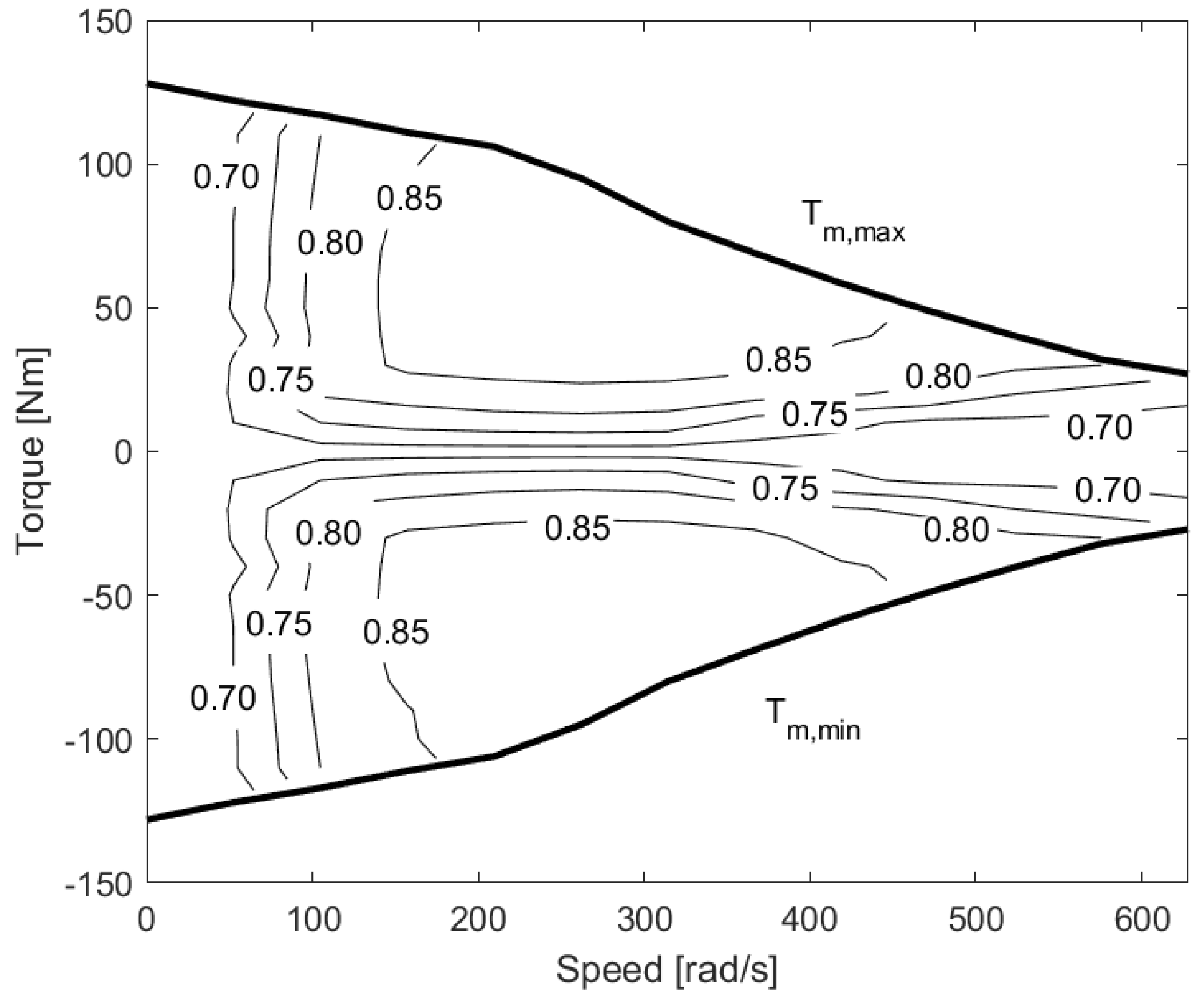
2.1.4. Electric Motor

Electric motor was modeled based on simulation data obtained from ADVISOR [35]. Efficiency map η e m = f ( T e m , ω e m ) , torque vector T e m , speed vector ω e m , and motor inertia J e m were imported from ADVISOR. Drag torque is obtained as follows:
T e m , d r a g = J e m · Δ ω e m .
The electric motor power is defined as follows:
P e m = T e m · ω e m · 1 η e m ( ω e m , T e m ) , P e m , d > 0 T e m · ω e m · η e m ( ω e m , T e m ) , P e m , d < 0 ,
where P e m , d is electric motor power demand.
The detailed simulation data for Mannesmann Sachs 25 kW permanent magnet motor was obtained from ADVISOR [35]. Efficiency map of this motor is shown in Figure 5.

2.1.5. Battery Pack

Various methodologies exist for battery modeling, as discussed extensively in the literature [36]. However, for the purposes of this study, an electrical circuit model was employed, thus leveraging data sourced from ADVISOR. Specifically, the battery input/output power was determined based on the total power requested (or supplied) by the electric motor P e m , t o t . The battery current is derived from the power balancing equation as follows:
I b a t ( P e m , t o t ) = V o c V o c 2 4 · R i · P e m , t o t 2 · R i ,
where V o c represents the open circuit voltage of the battery, while R i denotes the battery’s internal resistance. The battery state of charge is calculated as follows:
S O C k + 1 = I b a t · η b a t ( I b a t ) 3600 · Q b a t + S O C k ,
where Q b a t is the battery capacity, and η b a t is the battery charging efficiency, which is defined as follows:
η b a t = 1.0 I b a t 0 0.9 I b a t < 0 .
As an initial reference model, detailed simulation data for a 6.5 Ah NiMH battery was acquired from ADVISOR. Subsequently, these data were adjusted to scale with the specifications of the electric motor and other powertrain components.

2.2. Dynamic Programming

To evaluate the influence of varying HFs on fuel consumption, it is essential to devise an appropriate EMS that ensures consistent behavior across all analyzed configurations. A singularly defined EMS would most certainly not be optimal for varying parameters of the powertrain. As previously mentioned, much of the available literature on component sizing has either employed simple rule-based EMS or neglected EMS altogether [25]. However, for optimal system-level design and to obtain valid, comparable results across different powertrain configurations, both sizing and EMS derivation must be conducted together. As highlighted in [37], powertrain component sizing is intricately linked to the EMS, which determines the power split between different energy flow paths. The authors in [26,38] concluded that EMS is invariably coupled with component sizing for hybrid electric vehicles. Consequently, it is impossible to claim that any powertrain is optimal unless the trajectory of the battery’s SOC and the distribution of power between energy sources are optimally controlled. The EMS regulates the operating points of the ICE, thereby controlling the charging and discharging of the battery.
In this study, the DP technique was employed to solve the optimal control problem. By determining the optimal EMS for each analyzed powertrain configuration, maximum performance is achieved, thus facilitating valid and unbiased comparisons. The DP optimization algorithm operates on the principle of optimality, which traditionally requires prior knowledge of the entire drive cycle. However, advancements in optimization methods based on DP, such as predictive or adaptive techniques, eliminate this requirement, thereby making DP applicable even under uncertain driving conditions [39]. Other techniques, such as an adaptive EMS based on the artificial neural network Pontryagin’s principle of minimization proposed in [40], could be applied. However, because the drive cycle was known a priori in this study, along with the rest of the vehicle parameters, the standard DP technique was used.
In the discrete time format, the model of the hybrid electric vehicle is expressed as follows:
x k + 1 = f ( x ( k ) , u ( k ) ) , k = 1 , . . . , N 1 ,
where x ( k ) represents the state vector of the system, while u ( k ) denotes the vector of control variables, i.e., ICE and motor speeds, as well as gear shift command to the transmission. The drive cycle was assumed to be known in advance, and a sampling time of one second was selected for this control problem. The optimization objective is to determine the control input u ( k ) that minimizes the fuel consumption. The fuel consumption cost function is defined as follows:
k = 0 N 1 g k ( x k , u k ) .
Additionally, another factor g N ( x N ) , representing the final cost, is introduced here as follows:
g N ( x N ) = 0 S O C ( N ) = S O C ( 0 ) = 0.65 otherwise
to enforce charge-sustaining operation. Although the initial value of S O C ( 0 ) is randomly chosen, it has negligible impact on the total fuel consumption. The optimal control input u ( k ) is thus determined to minimize the overall cost function:
J = g N ( x N ) + k = 0 N 1 g k ( x k , u k ) .
The optimization problem is solved backward in accordance with Bellman’s Principle of Optimality [41], whereby the optimal policy is obtained by first solving one-stage subproblems involving only the last stage, thereby gradually extending to subproblems involving the last two stages, and so forth, until the entire problem is resolved. This approach decomposes the overall dynamic optimization problem into a sequence of simpler minimization problems. A MATLAB implementation of DP, based on [42], was utilized that includes one state variable, i.e., SOC. The SOC variable was constrained within the range of [ 0.5 , 0.8 ] to ensure that the battery operated efficiently while maintaining sufficient stored electric energy. The initial and final SOC values were selected as 0.65, which are within safe battery limits. This continuous state space was discretized into a grid with 61 points. Accurate determination of the state of charge boundaries is crucial, as the optimal state of charge trajectory ultimately intersects these boundaries during the final braking phase of the drive cycle, thus facilitating maximal recuperation [43]. When employing DP, a torque split factor is often utilized as a control variable [44,45,46] to determine the distribution of torque between the engine and the motor. However, in the case where the motor and engine are speed-coupled, such a factor becomes redundant. Instead, the motor speed is employed as a control variable. Considering that the electric motor and the ICE were speed-coupled, as depicted in Figure 4, this kinematic link allows for determining the speed of the internal combustion engine when the speed of the electric motor is known by using the following equation:
ω s = ω c · ( 1 + k ) ω r · k ,
where ω a , ω c , and ω r represent the speeds of the sun, carrier, and ring gear, respectively. This equation provides flexibility in the operation of the ICE, as it allows the electric motor speed to be adjusted so that the ICE remains within its more efficient operating regions. This flexibility is illustrated in Figure 6. Note that additional transmission elements exist between the planetary gearset components and the motor and ICE, but these have been omitted in the illustration for clarity and simplicity.
The model is solved in a backward fashion, where the torques of the planetary gear elements are calculated as follows:
T s = T r k T c = T r · 1 + k k
where T s , T c , and T r represent the torques of the sun gear, carrier gear, and ring gear, respectively. The ICE torque and speed are then derived using the gearbox ratio i g b as follows:
T e = T c i g b ω e = ω c · i g b ,
where T e and ω e denote ICE torque and speed. By knowing these parameters, and by using the Willans line method, the ICE fuel consumption can be determined as a function of torque and speed, which gives us g = f ( ω e , T e ) . By utilizing these equations, the DP algorithm then determines the optimal motor speed to ensure that the engine operates in the most efficient region possible for a given drive cycle instance. The motor speed is constrained by the physical limits of the electric motor [ ω e m , m a x , ω e m , m a x ] , and discretized into a grid of 261 points, while gear number variable ranges from 1 to 5 and is discretized into 5 grid points. Other physical constraints, including the engine operating range and battery limits, were also incorporated into the algorithm. These control variables and state variable, together with the number of steps N, function to represent the physical model of the vehicle, and the velocity and acceleration, as predefined by the drive cycle, are the main inputs to the DP algorithm. The algorithm then calculates the fuel consumption of the engine based on the calculated ICE speed and ICE torque derived from the power demand. In output, an optimal control map, specifying the optimal control signals at each time step and at each state, is obtained, thus minimizing fuel consumption while maintaining charge-sustaining operation. It is important to note that by optimizing the control input for motor speed, the resultant optimal power split between the ICE and motor is obtained, thus inherently optimizing the EMS as well. This approach enables an unbiased comparison of configurations with different hybridization ratios.

2.3. Model Integration and Scaling

As previously mentioned, the model components must be scalable to facilitate the simulation of various hybridization levels. The ICE was scaled based on the engine displacement V d while maintaining a constant bore-to-stroke ratio to ensure consistent engine speed across different engine sizes and to ensure comparable results.
Given the substantial weight of the armor on the HETV, mass was assumed to remain constant, thus rendering the weight difference resulting from the increase in battery and motor weight and the decrease in ICE weight negligible.
For hybridization to yield comparable results, it is imperative to compare configurations with equivalent performance. This is achieved by maintaining a constant power-to-weight ratio, thus ensuring that the sum of the electric motors’ power and ICE power remains consistent. Only HFs smaller than 0.6 were explored. Vehicles with higher HFs typically demonstrate low gradeability, are charge-depleting, and demand unreasonably large batteries, despite the potential for achieving better fuel economy under certain configurations [47].
The scalability of the electric motor is attained through the utilization of a linear scaling factor for torque. This approach yields sufficiently accurate results while remaining computationally efficient [48,49]. The power of the electric motors was determined by the constant power-to-weight ratio.
In the battery model, the open circuit voltage remains constant, while the internal resistance is scaled based on the battery capacity. The determination of the battery’s maximum power aligns with the combined maximum powers of the electric motors, thus dictating the maximum battery current and, consequently, the battery capacity.
After establishing the optimal HF with engine displacement as the primary scaling parameter, the focus shifted to examining two other design parameters: battery capacity and bore-to-stroke ratio. These parameters were chosen because they do not affect the HF or total power. While maintaining a constant HF, keeping the engine displacement unchanged means that adjusting the stroke requires a corresponding alteration in the bore to maintain consistency. Consequently, the bore-to-stroke ratio was selected for analysis. This approach enables the evaluation of how additional design parameters of the two energy sources impact total fuel economy by varying the values of these parameters.

3. Results

To analyze the impact of hybridization on fuel consumption optimization, dynamic programming was employed for downsized configurations. The displacement V d was systematically reduced in absolute decrements of 5% down to 50% of its original size. Additionally, the drive cycle, as illustrated in Figure 2, was segmented into two terrains: hard and soft. Optimization was performed separately for each terrain, as well as for the entire drive cycle, to discern the influence of different driving conditions on the optimal hybridization of parallel HETV powertrains. The details of the simulation parameters are shown in Table 1.
Figure 7 demonstrates the impact of hybridization on fuel consumption in parallel HETVs. For the entire drive cycle, the optimal HF was determined to be 0.48. With this HF, the parameters of the powertrain components were obtained and are presented in Table 2, while the operating points of the ICE and the electric motor are illustrated in Figure 8. Note that only one motor is shown, as they operate very similarly. The influence of drive cycle on HF is significant, as detailed in Table 3.
The DP algorithm determined the optimal control inputs between the ICE and motor, with the corresponding operating modes illustrated in Figure 9, thus effectively maintaining the SOC and ensuring consistent initial and final values for charge-sustaining operation, as depicted in Figure 10.
As shown in Figure 9, the drive cycle was divided into three equal parts to enhance visibility. Each operating mode is represented by a distinct color: red for engine only, green for motor only, magenta for hybrid, yellow for charging, and blue for regenerative braking. The white areas indicate periods when the vehicle was not moving. The SOC can be seen plotted over these operating modes, thus demonstrating how the DP algorithm effectively managed the charge-sustaining operation throughout the drive cycle.

Parameter Sensitivity Analysis

To comprehensively understand the impacts of specific key design parameters, a parameter sensitivity analysis was conducted. Firstly, the engine bore-to-stroke ratio and battery capacity were addressed, as they were not originally included in the sizing problem and can be varied without influencing the HF. These parameters were varied within the range of [ 30 % , + 30 % ] of their initial values, as presented in Table 2. The simulation was executed over the entire drive cycle. The relationship between changes in the fuel economy and varying battery capacity values is depicted in Figure 11.
Similarly, the relationship between changes in the fuel economy and varying bore-to-stroke ratios is illustrated in Figure 12.
The parameters initially addressed in the sizing problem, specifically the ICE displacement V d and motor torque scaling factor, underwent variation without maintaining the constraint H F = c o n s t . The relationship between these parameters and the fuel economy is depicted in Figure 13.
Note that reducing the value of V d by more than 10% from its original value rendered the problem infeasible. Downsizing the ICE and motor resulted in a decrease in fuel consumption in both cases by a certain margin, but they also reduced the total available power, thus jeopardizing vehicle performance. Specifically, reducing the V d by 10% reduced the ICE power by 15 kW.
The influence of individual parameters on the total fuel economy is depicted in Figure 14. This illustration presents the average fuel consumption change of 10% change for each parameter for the adopted configuration and drive cycle.

4. Discussion

The optimal HF for the entire drive cycle was determined to be 0.48. Notably, a higher HF was observed during the higher-speed segment of the drive cycle, while a lower HF was observed during the lower-speed segment. This phenomenon can be attributed to the lower occurrence of start–stop events and generally less variation in speed events during the higher-speed segment. This enables the efficient operation of the ICE through optimal gearshifting and effective complementation by the electric motor through speed-coupling, all while maintaining efficient operation. Consequently, the ICE can operate more consistently within its efficient operating range, thereby contributing to improved fuel economy at higher HF levels while reducing the need for electric power usage.
Intuitively, one might expect that significant variations in speed and a higher availability of regenerative energy would correspond to a higher HF due to the capability of electric motors to harness that energy. Thus, one would anticipate the soft terrain segment of the drive cycle to have a higher HF. However, for HETVs, this expectation does not hold true. This can be explained by the inability of electric motors in parallel HETVs to effectively complement ICE operation in drive cycles with significant variations in speed. In cycles with significant variations in speed, electric motors often operate at low-efficiency regions in order to complement efficient engine operation while requiring the engine to charge the battery due to the big electric energy usage, thus establishing an inefficient energy conversion chain. It is important to note that this feature was observed for the adopted HETV configuration and could differ for other configurations.
The soft terrain segment had more available energy for recuperation, as indicated by the data presented in Table 4. However, although a higher HF would imply higher regenerative braking, this was not the case in this research. This observation aligns with previous research findings, such as those discussed in [22], where they suggested that tracked vehicles experience low energy recuperation due to their low speeds and the high running resistance coefficient of their tracks. The SOC profiles depicted in Figure 10 further support previous conclusions. For the hard segment of the drive cycle, the DP algorithm showed minimal variation, thus indicating efficient ICE operation with smaller electric motor engagement. Conversely, in the case of the soft segment of the drive cycle, the DP algorithm showed a greater variation in the SOC, thus indicating higher electric energy usage, as expected. However, in both cases, the SOC variation was generally small, and the charge-sustaining operation was preserved at all times. Nonetheless, for the entire drive cycle, the DP algorithm distinguishes between the two segments, thus allowing for a deeper drop in the SOC during the first hard segment while ensuring energy recuperation during the subsequent soft segment, where greater opportunities for energy recuperation exist.
As previously mentioned, in this study, the EMS was determined within the DP algorithm, thus effectively obtaining the optimal EMS for a specific drive cycle and HF. The operating points of the ICE and the electric motor largely fell within their efficient regions, which was particularly noteworthy for the ICE. However, a significant portion of their operation occurred outside these optimal zones, thus emphasizing the impact of the engine–load connection in the parallel hybrid configuration. Importantly, the electric motor’s load-leveling characteristics often necessitate operation outside its efficient range to enhance the overall efficiency of the ICE. Nonetheless, further enhancements, especially for the electric motor, could be realized with a similar, albeit slightly modified configuration involving different gear ratios. The DP algorithm determines the optimal motor speed based on the external power demand, thus resulting in the identification of five operating modes, as illustrated in Figure 9:
  • Engine only;
  • Motor only;
  • Hybrid;
  • Charging;
  • Regenerative braking.
Interestingly, these operating modes were predefined in the design of a rule-based EMS for a similar hybrid powertrain configuration for HETVs, as discussed in [19]. Notably, engine-only and motor-only modes rarely occur compared to the hybrid mode, where both the engine and motor are utilized for propulsion, particularly during the first half of the drive cycle. The second half of the drive cycle highlights the significant use of regenerative braking to recover the SOC and enable charge-sustaining operation.
It is worth noting that the charging mode, as defined in this study, occurs in certain parts of the drive cycle, albeit less frequently than reported in [19] and with a distinction. Here, the charging mode signified a negative power demand, i.e., energy regeneration, with the engine also supplying some of the charging energy via the planetary gear system. In contrast, the same operating mode in [19] involved vehicle propulsion via the engine while charging batteries, but such an occurrence has been here proved negligible, as it happens in small time frames when the power demand switches from positive to negative. However, the charging potential of this mode at HF = 0.48 was low, thus essentially maintaining charge sustainability with a negligible SOC increase that was primarily applied in the first half of the drive cycle, where regenerative braking potential was limited, as is evident in Figure 9.
Additionally, the results indicate that the battery capacity does not significantly influence fuel economy, thus confirming earlier findings from [50], where the ADVISOR 3.2 software was utilized to assess the impact of the battery capacity on the fuel economy of hybrid electric wheeled vehicles with series-parallel powertrain configurations.
On the other hand, the influence of the engine bore-to-stroke ratio on fuel consumption was substantial and is consistent with published research, which has suggested increased engine efficiency at lower bore-to-stroke ratios attributed to lower heat transfer losses and faster combustion [51,52].
An important revelation from the results is that the engine parameters were shown to exert the most significant influence on the fuel economy. Therefore, it is imperative to conduct thorough ICE sizing, thereby considering not only power requirements but also parameters such as the ICE displacement and bore-to-stroke ratio. The distribution of influence among individual parameters on the fuel economy closely resembles the published findings in [22,53], where optimal sizing was achieved through the application of the genetic algorithm. This agreement in findings serves to validate the results presented here.

5. Conclusions

This paper addressed the optimization of powertrain component sizes in speed-coupled parallel HETVs and evaluated the influence of key powertrain design parameters on overall efficiency. Despite the growing interest in hybrid propulsion systems for tracked vehicles, research in this area remains limited, particularly for parallel configurations. To address this gap, a custom drive cycle, scalable vehicle model, and dynamic programming algorithm were developed in MATLAB. A hybridization factor was adopted as a key quantifier of hybridization, while the DP determined the EMS and provided an equal basis for comparing configurations with different HFs. The results indicate that the optimal hybridization factor for parallel HETVs is 0.48 for the adopted drive cycle. This optimal HF was found to vary significantly across different segments of the drive cycle, with higher HFs observed during higher-speed segments due to more efficient ICE operation and effective electric motor complementation.
A comprehensive parameter sensitivity analysis was also conducted, thus revealing that engine parameters such as the displacement and bore-to-stroke ratio significantly influenced the total fuel economy. This analysis underscores the importance of these parameters in achieving optimal system performance. For instance, a 10% change in these parameters can result in close to a 2% change in the total fuel economy.
While this study demonstrated that parallel HETVs are feasible and capable of charge-sustaining operation, as well as provided a robust foundation for optimizing hybrid propulsion systems in parallel HETVs, it is important to note that this study did not account for energy losses during clutch engagement, engine starting, or variations in gear ratios and gearbox efficiency, i.e., it is configuration-specific. Therefore, future research will focus on higher fidelity models that account for energy losses during clutch engagement, engine starting, and variations in gear ratios and gearbox efficiency. Additionally, forward-looking models will be developed to assess vehicle performance comprehensively.

Author Contributions

Conceptualization, S.M. (Stefan Milicevic) and I.B.; methodology, S.M. (Stefan Milicevic) and M.B.; software, S.M. (Stefan Milicevic) and S.M. (Sasa Milojevic); validation, S.M. (Stefan Milicevic), I.B., M.B. and B.S.; formal analysis, S.M. (Stefan Milicevic), I.B., S.M. (Sasa Milojevic), M.B. and B.S.; investigation, S.M. (Stefan Milicevic) and S.M. (Sasa Milojevic); resources, S.M. (Sasa Milojevic) and B.S.; data curation, S.M. (Stefan Milicevic), I.B. and M.B.; writing—original draft preparation, S.M. (Stefan Milicevic); writing—review and editing, S.M. (Stefan Milicevic), I.B., S.M. (Sasa Milojevic), and M.B.; visualization, S.M. (Stefan Milicevic); supervision, I.B., S.M. (Sasa Milojevic), and B.S. All authors have read and agreed to the published version of the manuscript.

Funding

This research received no external funding.

Data Availability Statement

The data that support the findings of this study are available from the corresponding author upon reasonable request due to privacy and confidentiality concerns.

Conflicts of Interest

The authors declare no conflicts of interest.

Abbreviations

The following abbreviations are used in this manuscript:
HETVHybrid Electric Tracked Vehicle
EMTElectromechanical Transmission
EMSEnergy Management Strategy
SOCState of Charge
ICEInternal Combustion Engine
HFHybridization Factor
DPDynamic Programming

References

  1. Wong, J.Y.; Huang, W. “Wheels vs. tracks”—A fundamental evaluation from the traction perspective. J. Terramech. 2006, 43, 27–42. [Google Scholar] [CrossRef]
  2. Khalil, G. Challenges of hybrid electric vehicles for military applications. In Proceedings of the 2009 IEEE Vehicle Power and Propulsion Conference, Dearborn, MI, USA, 7–10 September 2009; IEEE: Piscataway, NJ, USA, 2009; pp. 1–3. [Google Scholar]
  3. Galvagno, E.; Rondinelli, E.; Velardocchia, M. Electro-mechanical transmission modelling for series-hybrid tracked tanks. Int. J. Heavy Veh. Syst. 2012, 19, 256–280. [Google Scholar] [CrossRef]
  4. Randive, V.; Subramanian, S.C.; Thondiyath, A. Design and analysis of a hybrid electric powertrain for military tracked vehicles. Energy 2021, 229, 120768. [Google Scholar] [CrossRef]
  5. Randive, V.; Subramanian, S.C.; Thondiyath, A. Component sizing of single and dual drive series hybrid electric powertrain for military tracked vehicles. In Proceedings of the 2019 IEEE Vehicle Power and Propulsion Conference (VPPC), Hanoi, Vietnam, 14–17 October 2019; IEEE: Piscataway, NJ, USA, 2019; pp. 1–6. [Google Scholar]
  6. Zou, Y.; Sun, F.; Hu, X.; Guzzella, L.; Peng, H. Combined optimal sizing and control for a hybrid tracked vehicle. Energies 2012, 5, 4697–4710. [Google Scholar] [CrossRef]
  7. Qin, Z.; Luo, Y.; Zhuang, W.; Pan, Z.; Li, K.; Peng, H. Simultaneous optimization of topology, control and size for multi-mode hybrid tracked vehicles. Appl. Energy 2018, 212, 1627–1641. [Google Scholar] [CrossRef]
  8. Zhang, W.; Wang, J.; Du, S.; Ma, H.; Zhao, W.; Li, H. Energy management strategies for hybrid construction machinery: Evolution, classification, comparison and future trends. Energies 2019, 12, 2024. [Google Scholar] [CrossRef]
  9. Milićević, S.V.; Blagojević, I.A. Component sizing and energy management for a series hybrid electric tracked vehicle. Vojnoteh. Glas. Tech. Cour. 2022, 70, 877–896. [Google Scholar] [CrossRef]
  10. Du, G.; Zou, Y.; Zhang, X.; Kong, Z.; Wu, J.; He, D. Intelligent energy management for hybrid electric tracked vehicles using online reinforcement learning. Appl. Energy 2019, 251, 113388. [Google Scholar] [CrossRef]
  11. Han, R.; Lian, R.; He, H.; Han, X. Continuous reinforcement learning-based energy management strategy for hybrid electric-tracked vehicles. IEEE J. Emerg. Sel. Top. Power Electron. 2021, 11, 19–31. [Google Scholar] [CrossRef]
  12. Han, X.; He, H.; Wu, J.; Peng, J.; Li, Y. Energy management based on reinforcement learning with double deep Q-learning for a hybrid electric tracked vehicle. Appl. Energy 2019, 254, 113708. [Google Scholar] [CrossRef]
  13. Liu, T.; Zou, Y.; Liu, D.; Sun, F. Reinforcement learning–based energy management strategy for a hybrid electric tracked vehicle. Energies 2015, 8, 7243–7260. [Google Scholar] [CrossRef]
  14. Su, Q.; Huang, R.; He, H. Heterogeneous multi-agent deep reinforcement learning for eco-driving of hybrid electric tracked vehicles: A heuristic training framework. J. Power Sources 2024, 601, 234292. [Google Scholar] [CrossRef]
  15. Silvas, E.; Hofman, T.; Murgovski, N.; Etman, L.P.; Steinbuch, M. Review of optimization strategies for system-level design in hybrid electric vehicles. IEEE Trans. Veh. Technol. 2016, 66, 57–70. [Google Scholar] [CrossRef]
  16. Guzzella, L.; Sciarretta, A. Vehicle Propulsion Systems; Springer: Berlin/Heidelberg, Germany, 2007; Volume 1. [Google Scholar]
  17. Zou, Y.; Li, J.; Hu, X.; Chamaillard, Y. Modeling and Control of Hybrid Propulsion System for Ground Vehicles; Springer: Berlin/Heidelberg, Germany, 2018. [Google Scholar]
  18. Milićević, S.; Muždeka, S. Modelling and performance analysis of the BVP M-80A hybrid drive. Vojnoteh. Glas. Tech. Cour. 2021, 69, 64–87. [Google Scholar] [CrossRef]
  19. Milićević, S.V.; Blagojević, I.A.; Muždeka, S.R. Advanced rule-based energy management for better fuel economy of hybrid electric tracked vehicle. FME Trans. 2021, 49, 711–718. [Google Scholar] [CrossRef]
  20. Katrasnik, T.; Trenc, F.; Opresnik, S.R. Analysis of energy conversion efficiency in parallel and series hybrid powertrains. IEEE Trans. Veh. Technol. 2007, 56, 3649–3659. [Google Scholar] [CrossRef]
  21. Banjac, T.; Trenc, F.; Katrašnik, T. Energy conversion efficiency of hybrid electric heavy-duty vehicles operating according to diverse drive cycles. Energy Convers. Manag. 2009, 50, 2865–2878. [Google Scholar] [CrossRef]
  22. Zhang, B.; Guo, S.; Lv, Q.; Zhang, X.; Ouyang, M.; Teng, L. Quantitative analysis of the energy saving mechanism of a hybrid electric tracked vehicle by an analytical method. Energy Convers. Manag. 2021, 237, 114067. [Google Scholar] [CrossRef]
  23. Zhuang, W.; Li, S.; Zhang, X.; Kum, D.; Song, Z.; Yin, G.; Ju, F. A survey of powertrain configuration studies on hybrid electric vehicles. Appl. Energy 2020, 262, 114553. [Google Scholar] [CrossRef]
  24. Li, X.; Williamson, S.S. Comparative investigation of series and parallel hybrid electric vehicle (HEV) efficiencies based on comprehensive parametric analysis. In Proceedings of the 2007 IEEE Vehicle Power and Propulsion Conference, Arlington, TX, USA, 9–12 September 2007; IEEE: Piscataway, NJ, USA, 2007; pp. 499–505. [Google Scholar]
  25. Huang, Y.; Wang, H.; Khajepour, A.; Li, B.; Ji, J.; Zhao, K.; Hu, C. A review of power management strategies and component sizing methods for hybrid vehicles. Renew. Sustain. Energy Rev. 2018, 96, 132–144. [Google Scholar] [CrossRef]
  26. Xu, L.; Mueller, C.D.; Li, J.; Ouyang, M.; Hu, Z. Multi-objective component sizing based on optimal energy management strategy of fuel cell electric vehicles. Appl. Energy 2015, 157, 664–674. [Google Scholar] [CrossRef]
  27. Wong, J.Y. Theory of Ground Vehicles; John Wiley & Sons: Hoboken, NJ, USA, 2022. [Google Scholar]
  28. Rizzo, D.M. Military Vehicle Optimization and Control; Michigan Technological University: Houghton, MI, USA, 2014. [Google Scholar]
  29. Milićević, S.V.; Blagojević, I.A. Theoretical model of high-speed tracked vehicle general motion. FME Trans. 2023, 51, 449–456. [Google Scholar] [CrossRef]
  30. Urlaub, A. Verbrennungsmotoren: Grundlagen, Verfahrenstheorie, Konstruktion; Springer: Berlin/Heidelberg, Germany, 2013. [Google Scholar]
  31. Sorrentino, M.; Mauramati, F.; Arsie, I.; Cricchio, A.; Pianese, C.; Nesci, W. Application of Willans Line Method for Internal Combustion Engines Scalability towards the Design and Optimization of Eco-Innovation Solutions; Technical Report, SAE Technical Paper; SAE: Warrendale, PA, USA, 2015. [Google Scholar]
  32. Suijs, W.; Verhelst, S. Scaling Performance Parameters of Reciprocating Engines for Sustainable Energy System Optimization Modelling. Energies 2023, 16, 7497. [Google Scholar] [CrossRef]
  33. Rizzoni, G.; Guzzella, L.; Baumann, B.M. Unified modeling of hybrid electric vehicle drivetrains. IEEE/ASME Trans. Mechatronics 1999, 4, 246–257. [Google Scholar] [CrossRef]
  34. Milićević, S.V.; Blagojević, I.A. Optimization of gear ratios and gear-shifting strategy for enhanced efficiency in tracked vehicles. Vojnoteh. Glas. 2023, 71, 1028–1047. [Google Scholar] [CrossRef]
  35. Markel, T.; Brooker, A.; Hendricks, T.; Johnson, V.; Kelly, K.; Kramer, B.; O’Keefe, M.; Sprik, S.; Wipke, K. ADVISOR: A systems analysis tool for advanced vehicle modeling. J. Power Sources 2002, 110, 255–266. [Google Scholar] [CrossRef]
  36. Tamilselvi, S.; Gunasundari, S.; Karuppiah, N.; Razak, R.K.A.; Madhusudan, S.; Nagarajan, V.M.; Sathish, T.; Shamim, M.Z.M.; Saleel, C.A.; Afzal, A. A review on battery modelling techniques. Sustainability 2021, 13, 10042. [Google Scholar] [CrossRef]
  37. Malikopoulos, A.A. Impact of component sizing in plug-in hybrid electric vehicles for energy resource and greenhouse emissions reduction. J. Energy Resour. Technol. 2013, 135, 041201. [Google Scholar] [CrossRef]
  38. Azad, N.L.; Mozaffari, A.; Vajedi, M.; Masoudi, Y. Chaos oscillator differential search combined with Pontryagin’s minimum principle for simultaneous power management and component sizing of PHEVs. Optim. Eng. 2016, 17, 727–760. [Google Scholar] [CrossRef]
  39. Kong, Y.; Xu, N.; Liu, Q.; Sui, Y.; Yue, F. A data-driven energy management method for parallel PHEVs based on action dependent heuristic dynamic programming (ADHDP) model. Energy 2023, 265, 126306. [Google Scholar] [CrossRef]
  40. Ma, Z.; Luan, Y.; Zhang, F.; Xie, S.; Coskun, S. A data-driven energy management strategy for plug-in hybrid electric buses considering vehicle mass uncertainty. J. Energy Storage 2024, 77, 109963. [Google Scholar] [CrossRef]
  41. Bellman, R. Dynamic programming. Science 1966, 153, 34–37. [Google Scholar] [CrossRef] [PubMed]
  42. Sundstrom, O.; Guzzella, L. A generic dynamic programming Matlab function. In Proceedings of the 2009 IEEE Control Applications,(CCA) & Intelligent Control, (ISIC), St. Petersburg, Russia, 8–10 July 2009; IEEE: Piscataway, NJ, USA, 2009; pp. 1625–1630. [Google Scholar]
  43. Sundström, O.; Guzzella, L.; Soltic, P. Optimal hybridization in two parallel hybrid electric vehicles using dynamic programming. IFAC Proc. Vol. 2008, 41, 4642–4647. [Google Scholar] [CrossRef]
  44. Lin, C.C.; Peng, H.; Grizzle, J.W.; Kang, J.M. Power management strategy for a parallel hybrid electric truck. IEEE Trans. Control Syst. Technol. 2003, 11, 839–849. [Google Scholar]
  45. Liu, T.; Tan, K.; Zhu, W.; Feng, L. Computationally Efficient Energy Management for a Parallel Hybrid Electric Vehicle Using Adaptive Dynamic Programming. IEEE Trans. Intell. Veh. 2023, 9, 4085–4099. [Google Scholar] [CrossRef]
  46. Li, G.; Görges, D. Fuel-efficient gear shift and power split strategy for parallel HEVs based on heuristic dynamic programming and neural networks. IEEE Trans. Veh. Technol. 2019, 68, 9519–9528. [Google Scholar] [CrossRef]
  47. Lukic, S.M.; Emadi, A. Effects of drivetrain hybridization on fuel economy and dynamic performance of parallel hybrid electric vehicles. IEEE Trans. Veh. Technol. 2004, 53, 385–389. [Google Scholar] [CrossRef]
  48. Madhusudhanan, A.K.; Na, X.; Cebon, D. A computationally efficient framework for modelling energy consumption of ICE and electric vehicles. Energies 2021, 14, 2031. [Google Scholar] [CrossRef]
  49. Grunditz, E.; Thiringer, T. Modelling and Scaling Procedure of a Vehicle Electric Drive System; Report; Chalmers University of Technology: Göteborg, Sweden, 2017; p. 19. Available online: https://core.ac.uk/download/pdf/141718197.pdf (accessed on 8 June 2024).
  50. Somayajula, D.; Meintz, A.; Ferdowsi, M. Study on the effects of battery capacity on the performance of hybrid electric vehicles. In Proceedings of the 2008 IEEE Vehicle Power and Propulsion Conference, Harbin, China, 3–5 September 2008; IEEE: Piscataway, NJ, USA, 2008; pp. 1–5. [Google Scholar]
  51. Benajes, J.; Novella, R.; Pastor, J.; Hernández-López, A.; Duverger, T. A computational analysis of the impact of bore-to-stroke ratio on emissions and efficiency of a HSDI engine. Appl. Energy 2017, 205, 903–910. [Google Scholar] [CrossRef]
  52. Hoag, K.L.; Mangold, B.; Alger, T.; Abidin, Z.; Wray, C.; Walls, M.; Chadwell, C. A study isolating the effect of bore-to-stroke ratio on gasoline engine combustion chamber development. SAE Int. J. Engines 2016, 9, 2022–2029. [Google Scholar] [CrossRef]
  53. Milićević, S.V.; Blagojević, I.A. Powertrain Optimization Methodology Based on Scalable Modeling. In Proceedings of the 2023 31st Telecommunications Forum (TELFOR), Belgrade, Serbia, 21–22 November 2023; IEEE: Piscataway, NJ, USA, 2023; pp. 1–4. [Google Scholar]
Figure 1. Speed-coupled parallel configuration (LM and RM—left and right motor, respectively, S—sun gear, R—ring gear, C—planet carrier).
Energies 17 03531 g001
Figure 2. Drive cycle used for simulation.
Energies 17 03531 g002
Figure 3. Willams line approximation fit to real engine data.
Energies 17 03531 g003
Figure 4. HETV transmission (right side simplified scheme).
Energies 17 03531 g004
Figure 5. Electric motor efficiency map η m = f ( ω m , T m ) .
Energies 17 03531 g005
Figure 6. Force and speed diagrams of planetary gearset illustrating the ICE speed flexibility enabled by the motor speed range.
Energies 17 03531 g006
Figure 7. Fuel consumption at different hybridization factors in parallel HETVs.
Energies 17 03531 g007
Figure 8. Operating points of the ICE and the electric motor.
Energies 17 03531 g008
Figure 9. Operating modes decided by the DP optimization algorithm (entire drive cycle split in three parts for visibility; white color indicates vehicle not moving).
Energies 17 03531 g009
Figure 10. SOC profiles over normalized drive cycle duration.
Energies 17 03531 g010
Figure 11. Change in fuel economy for varying battery capacity values.
Energies 17 03531 g011
Figure 12. Change in fuel economy for varying bore-to-stroke ratios.
Energies 17 03531 g012
Figure 13. Change in fuel consumption for varying ICE displacements and motor torque scaling factors.
Energies 17 03531 g013
Figure 14. Averaged change in fuel consumption for 10% change in the individual powertrain parameter.
Energies 17 03531 g014
Table 1. Overview of simulation parameters.
ParameterValue
Vehicle mass13,850 kg
Track contact length3.3 m
Vehicle frontal area5.5 m 2
Sprocket radius0.26 m
Vehicle tread2.5 m
Planetary gear ratio2.546 kg/m3
Gearbox ratios i 1 = 4.428 ; i 2 = 2.087 ; i 3 = 1.406 ; i 4 = 0.944 ; i 5 = 0.647
Rolling resistance coefficient0.07
Air density1.2258 kg/m3
Drag coefficient1.1
Table 2. Powertrain component parameters obtained for the optimal HF.
Powertrain ComponentParameter Value
ICE P e , m a x = 148 kW, T e , m a x = 960 Nm, ω e , m a x = 220 rad/s, B / S = 1.21
Electric motors P e m , m a x = 71 kW, T e m , m a x = 370 Nm, ω e m , m a x = 630 rad/s
Battery Q b a t = 34 Ah, I b a t , m a x = 570 A
Table 3. Overview of optimal hybridization factor for each drive cycle.
Drive CycleHybridization Factor
Soft terrain0.27
Hard terrain0.59
Complete drive cycle0.48
Table 4. Energy available for recuperation overview.
Drive CycleEnergy Available for Recuperation
Soft terrain 592.4 kW/km
Hard terrain 1508.2 kW/km
Disclaimer/Publisher’s Note: The statements, opinions and data contained in all publications are solely those of the individual author(s) and contributor(s) and not of MDPI and/or the editor(s). MDPI and/or the editor(s) disclaim responsibility for any injury to people or property resulting from any ideas, methods, instructions or products referred to in the content.

