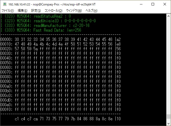
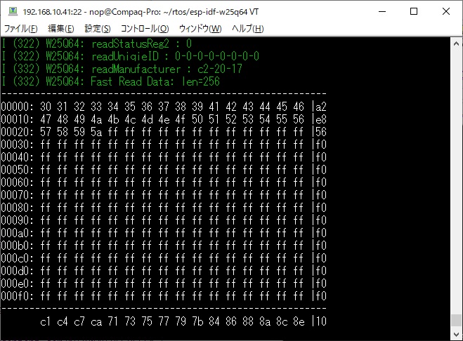
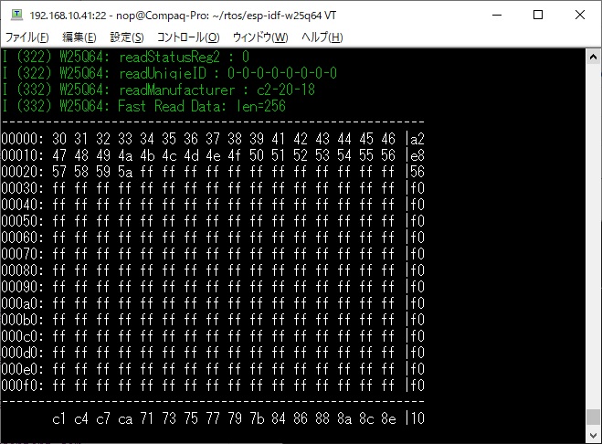
SPI Flash Memory W25Q64 Access Library for esp-idf.
I ported from here.
ESP-IDF V4.4/V5.x.
ESP-IDF V5.0 is required when using ESP32-C2.
ESP-IDF V5.1 is required when using ESP32-C6.
git clone https://github.com/nopnop2002/esp-idf-w25q64
cd esp-idf-w25q64
idf.py set-target {esp32/esp32s2/esp32s3/esp32c2/esp32c3/esp32c6}
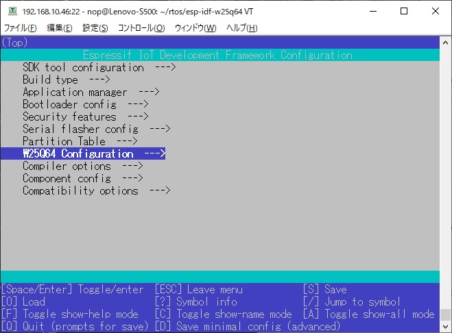
idf.py menuconfig
idf.py flash
Note for ESP32C3
For some reason, there are development boards that cannot use GPIO06, GPIO08, GPIO09, GPIO19 for SPI clock pins.
According to the ESP32C3 specifications, these pins can also be used as SPI clocks.
I used a raw ESP-C3-13 to verify that these pins could be used as SPI clocks.
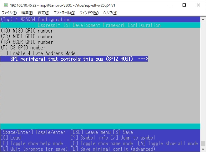
You have to set this config value with menuconfig.
- CONFIG_MISO_GPIO
GPIO number(IOxx) to MISO. - CONFIG_MOSI_GPIO
GPIO number(IOxx) to MOSI. - CONFIG_SCLK_GPIO
GPIO number(IOxx) to SCLK. - CONFIG_CS_GPIO
GPIO number(IOxx) to CS.
The ESP32 series has three SPI BUSs.
SPI1_HOST is used for communication with Flash memory.
You can use SPI2_HOST and SPI3_HOST freely.
When you use SDSPI(SD Card via SPI), SDSPI uses SPI2_HOST BUS.
When using this module at the same time as SDSPI or other SPI device using SPI2_HOST, it needs to be changed to SPI3_HOST.
When you don't use SDSPI, both SPI2_HOST and SPI3_HOST will work.
Previously it was called HSPI_HOST / VSPI_HOST, but now it is called SPI2_HOST / SPI3_HOST.
| # | W25Q64 | ESP32 | ESP32-S2/S3 | ESP32-C2/C3/C6 | |
|---|---|---|---|---|---|
| 1 | /CS | -- | GPIO5 | GPIO34 | GPIO3 |
| 2 | MISO | -- | GPIO19 | GPIO37 | GPIO0 |
| 3 | /WP | -- | 3.3V | 3.3V | 3.3V |
| 4 | GND | -- | GND | GND | GND |
| 5 | MOSI | -- | GPIO23 | GPIO35 | GPIO1 |
| 6 | SCK | -- | GPIO18 | GPIO36 | GPIO2 |
| 7 | /HOLD | -- | 3.3V | 3.3V | 3.3V |
| 8 | VCC | -- | 3.3V | 3.3V | 3.3V |
You can change it to any pin using menuconfig.
// Start Flash
void W25Q64_init(W25Q64_t * dev);
// Get status register1
esp_err_t W25Q64_readStatusReg1(W25Q64_t * dev, uint8_t * reg1);
// Get status register2(Winbond only)
esp_err_t W25Q64_readStatusReg2(W25Q64_t * dev, uint8_t * reg2);
// Get Unique ID(Winbond only)
esp_err_t W25Q64_readUniqieID(W25Q64_t * dev, uint8_t * id);
// Get JEDEC ID(Manufacture, Memory Type, Capacity)
esp_err_t W25Q64_readManufacturer(W25Q64_t * dev, uint8_t * id);
// Check busy
bool W25Q64_IsBusy(W25Q64_t * dev);
// Set power down mode
esp_err_t W25Q64_powerDown(W25Q64_t * dev);
// Set write enable
esp_err_t W25Q64_WriteEnable(W25Q64_t * dev);
// Set write disable
esp_err_t W25Q64_WriteDisable(W25Q64_t * dev);
// Read data from memory
uint16_t W25Q64_read(W25Q64_t * dev, uint32_t addr, uint8_t *buf, uint16_t n);
// First read data from memory
uint16_t W25Q64_fastread(W25Q64_t * dev, uint32_t addr, uint8_t *buf, uint16_t n);
// Erase data by Sector
bool W25Q64_eraseSector(W25Q64_t * dev, uint16_t sect_no, bool flgwait);
// Erase data by block(64KB)
bool W25Q64_erase64Block(W25Q64_t * dev, uint16_t blk_no, bool flgwait);
// Erase data by Block(32KB)
bool W25Q64_erase32Block(W25Q64_t * dev, uint16_t blk_no, bool flgwait);
// Erase all data
bool W25Q64_eraseAll(W25Q64_t * dev, bool flgwait);
// Write data to memory
int16_t W25Q64_pageWrite(W25Q64_t * dev, uint16_t sect_no, uint16_t inaddr, uint8_t* buf, int16_t n);
| Device | # of Bytes | Address range | # of 4K-Sectors | # of 32K-Blocks | # of 64K-Blocks | JEDEC ID |
|---|---|---|---|---|---|---|
| W25Q80 | 1M | 0x0FFFFF | 256 | 32 | 16 | EF-40-14 |
| W25Q16 | 2M | 0x1FFFFF | 512 | 64 | 32 | EF-40-15 |
| W25Q32 | 4M | 0x3FFFFF | 1024 | 128 | 64 | EF-40-16 |
| W25Q64 | 8M | 0x7FFFFF | 2048 | 256 | 128 | EF-40-17 |
| W25Q128 | 16M | 0xFFFFFF | 4096 | 512 | 256 | EF-40-18 |
The last two characters of the product name indicate operating parameters.
For example W25Q64BV, W25Q64CV, W25Q64FV, W25Q64JV are all the same 8 MB flash drives, but with different maximum frequencies and speeds.
In theory you could replace slow with fast, but the other way around might not work.
- BV: 80MHz clock operation
- CV: 104MHz clock operation
- FV: 104MHz clock operation
- JV: 133MHz clock operation
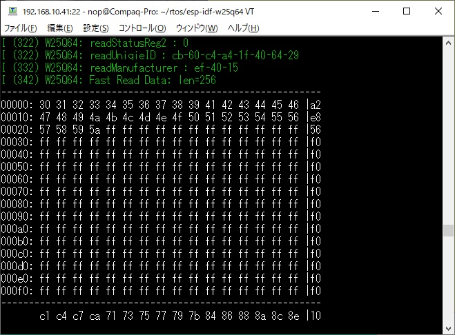
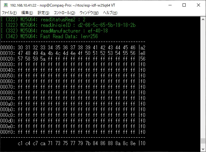
- Manufacturer:
Byte1 : ManufacturerID(0xEF=Winbond)
Byte2 : MemoryType(0x40=SPI/0x60=QPI)
Byte3 : Capacity(2^0x14=2^20=0x100000=1M Byte=8M Bit) - First 10Byte : ASCII 0-9
- Next 32Byte : ASCII A-Z
| Device | # of Bytes | Address range | # of 4K-Sectors | # of 32K-Blocks | # of 64K-Blocks | JEDEC ID |
|---|---|---|---|---|---|---|
| MX25L32 | 4M | 0x3FFFFF | 1024 | 128 | 64 | C2-20-16 |
| MX25L64 | 8M | 0x7FFFFF | 2048 | 256 | 128 | C2-20-17 |
| MX25L128 | 16M | 0xFFFFFF | 4096 | 512 | 256 | C2-20-18 |
| MX25L256 | 32M | 0x1FFFFFF(*1) | 8192 | 1024 | 512 | C2-20-19 |
The last one characters of the product name indicate operating parameters.
For example, MX25L3205, MX25L3205A, MX25L3205D, MX25L3206E are all the same 4 MB flash drives, but with different maximum frequencies and speeds.
In theory you could replace slow with fast, but the other way around might not work.
- MX25L3205 50MHz serial clock
- MX25L3205A 50MHz serial clock
- MX25L3205D 86MHz serial clock
- MX25L3206E 86MHz serial clock
(*1) Using 4 byte address mode.
- Manufacturer:
Byte1 : ManufacturerID(0xC2=Macronix)
Byte2 : MemoryType(0x20)
Byte3 : Capacity(2^0x16=2^22=0x400000=4M Byte=32M Bit)
4 byte address mode needs to be enabled.
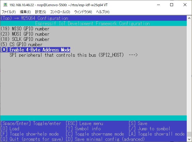
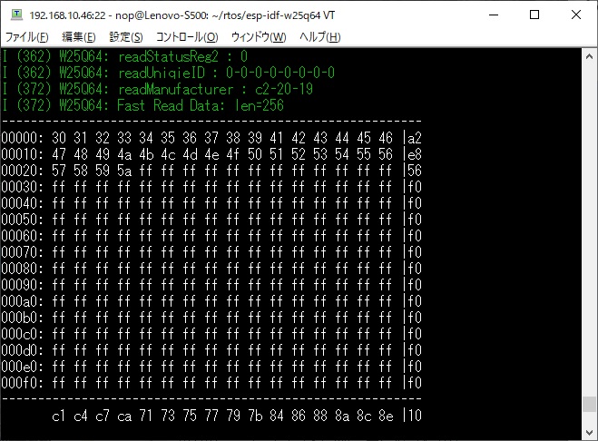
I tested these.
But I couldn't get it working.
- GD25Q64
- SST25VF016B
- SST25VF032B
There is a example to build a FAT file system on External SPI FLASH Memory is available here.
The ESP32's onboard FLASH is 4MByte, and you can reserve up to about 3MByte of storage on the onboard FLASH.
With the large capacity SPI FLASH Memory, you can add a large amount of storage.
You can access FLASH memory using C standard library functions such as fopen/fread/fwrite/fclose.
