S. Riaz Ahamed et al Int. Journal of Engineering Research and Applications
ISSN : 2248-9622, Vol. 5, Issue 1( Part 5), January 2015, pp.130-135
RESEARCH ARTICLE
www.ijera.com
OPEN ACCESS
Speed Control of Induction Motor by Using Intelligence
Techniques
S. Riaz Ahamed*, J. N. Chandra Sekhar**, Dinakara Prasad Reddy P***
Department of EEE, Sri Venkateswara University College of Engineering, Tirupati.
ABSTRACT
This paper gives the comparative study among various techniques used to control the speed of three phase
induction motor. In this paper, indirect vector method is used to control the speed of Induction motor. Firstly
Simulink Model is developed by using MATLAB/ Simulink software. PI controller, Fuzzy PI Hybrid controller,
Genetic Algorithm (GA) are the techniques involved in control Induction motor and the results are compared.
By converting three phase supply currents coming from stator to Flux and Torque components of current the
speed responses such as rise time, overshoot, settling time and speed regulation at load have been observed and
compared among the techniques. The PI controller parameters defined by an objective function are calculated by
using Genetic Algorithms presented good performance compared to Fuzzy PI Hybrid controller which has
parameters chosen by the human operator.
Keywords—Induction Motor, PI Controller, Fuzzy PI Hybrid Controller, Indirect Vector control, Genetic
Algorithm
I. Introduction
Now a day’s Induction motors are the work
horses of many industries which also replaced DC
machines with their various advantages like lack of
commutator, lower cost, reduced maintenance cost,
robust, less weight and rugged structure. Because of
their complex characteristics, it is not easier to
control the speed of Induction motor like DC motor,
so the vector control is used. It is introduced by
Blaschke and Hasse has resulted in remarkable
change in the field of electrical drives. Indirect vector
control is used in this paper which is one of the types
of vector control. It is very popular form of control of
Induction motor because this control strategy can
provide the same performance as achieved from a
separately excited DC Motor.
The simple structure and its good performance
has made the PI controller the best controller in the
industry. Its functions depends on two parameters
namely proportional gain Kp and Integral gain Ki.
Several methods can be used to tune PI controller.
The Fuzzy set theory, introduced by L.Zadeh is the
mathematical tool for Fuzzy Logic Controller (FLC).
It can be used in control of Induction Motor because
of its advantages such as it does not need a
mathematical model for the system, it is just based on
linguistic rules with IF-THEN general structure
which is based on human logic.
Methods such as Pole assignment method and
Ziegler-Nichols method have major inconvenience as
it is necessary to have prior knowledge of various
parameters of the Induction motor. An optimization
procedure can be developed to design the good
controller. Genetic Algorithm has been employed
www.ijera.com
successfully to solve the complex optimization
problems. The parameters of different controllers can
be determined by using Genetic Algorithm due to
their reasonable accuracy and fast convergence.
The PI controller parameters are determined by
minimizing Objective Function. The goal of this
work is to show that Optimization can be achieved by
optimization of PI Controller parameters. This can be
observed by comparing the results of Genetic
Algorithm based PI controller with PI, Fuzzy PI
Hybrid Controller.
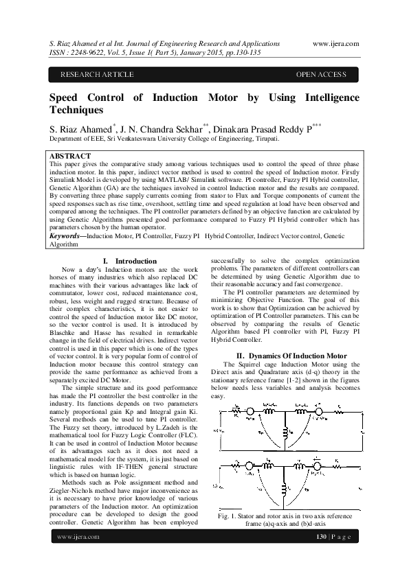
II. Dynamics Of Induction Motor
The Squirrel cage Induction Motor using the
Direct axis and Quadrature axis (d-q) theory in the
stationary reference frame [1-2] shown in the figures
below needs less variables and analysis becomes
easy.
Fig. 1. Stator and rotor axis in two axis reference
frame (a)q-axis and (b)d-axis
130 | P a g e
�S. Riaz Ahamed et al Int. Journal of Engineering Research and Applications
ISSN : 2248-9622, Vol. 5, Issue 1( Part 5), January 2015, pp.130-135
control induction motor drive namely Internal Pulse
Width Modulation current control loop and External
Speed control loop [3].
A. Electrical system of Induction Motor
�
�
0
0
=
R s + SLs
− Ls
SLm
− Lm
Ls
R s + SLs
Lm
SLm
SLm
− − r Lm R r + SLr − − r Lr
− r Lm
Lm
− r Lr R r + SLr
www.ijera.com
ids
iqs
idr
iqr
ϕqs = Ls iqs + Lm iqr
ϕds
= Ls ids _ + Lm idr
ϕqr = Lr iqr + Lm iqs
ϕdr
= Lr idr + Lm ids
Ls = Lls + Lm
Lr = Llr + Lm
Te =
3
2
P
2
ϕds iqs − ϕqs ids
A. Mechanical system of Induction Motor
1
d
=
T − F m − Tm
dt m 2H e
d
θ =
dt m
m
Where,
, � : Resistanceand leakage inductance of
stator
, � : Resistanceand leakage inductance of
rotor
�
: The magnetizing Inductance
Ls , Lr : Stator and rotor inductances
� , iqs : q axis component of stator voltage and
current
� , iqr :q axis component of rotor voltage and
current
� , ids :d axis component of stator voltage and
current
� , idr :d axis component of rotor voltage and
current
� , ϕds : q and d axis components of stator flux
� , ϕdr : q and d axis components of rotor flux
m : Angular velocity of rotor
θm : Angular position of rotor
P : Number of poles
�
p: Pairs of Poles ( )
2
: Electrical angular velocity ( . )
� : Electrical rotor angular position(� . )
Te : Electromagnetic Torque
Tm : Mechanical Torque on Shaft
J: Load Inertia Constant
F:Friction Coefficient
III. Indirect Vector Control
The block diagram shown below is the Indirect
Vector Control Technique. Two control loops will
www.ijera.com
Fig. 2. Block Diagram of Indirect Vector Control
Technique.
The indirect vector control method is essentially
the same as direct vector control, but the unit vector
signals (cos� and sin� ) are generated in feed
forward manner using the measured rotor speed
and the slip speed . Indirect vector control is
widely used in industrial applications. CurrentControlled PWM Inverter acts as three phase
sinusoidal current source to Induction motor. The
error between reference speed ∗ and speed
is
given to speed controller which outputs the command
Torque Te∗ .
A shown in the Block diagram above, Torque
and Rotor Flux can be independently controlled by qaxis stator current iqs and d-axis stator current ids
respectively.
The q-axis Stator Current Reference ∗ is
calculated from Command Torque Signal Te∗ as
shown in below equation.
2 2 Lr Te
i∗qs =
3 P Lm r
est
is the Estimated Rotor Flux Linkage. It can
be calculated by equation shown below.
Lm ids
=
r est
1 + τr s
L
Where τr = r is Time Constant of Rotor.
Rr
The d-axis stator current reference i∗ds
∗
.
calculated from Rotor flux reference input
i∗ds
=
r
∗
is
Lm
The rotor flux position � which is required for
coordinate transformation is calculated from slip
frequency sl and rotor speed as shown in equation
below.
θe =
dt
sl +
131 | P a g e
�S. Riaz Ahamed et al Int. Journal of Engineering Research and Applications
ISSN : 2248-9622, Vol. 5, Issue 1( Part 5), January 2015, pp.130-135
The slip frequency sl is calculated from stator
∗
and motor parameters.
reference current iqs
Lm R r ∗
i
sl =
Lr qs
r
est
∗
are converted
The current references i∗qs and ids
∗
∗
∗
into three phase currents , , by using Park’s
Transformation for the current regulators. The current
regulators will use the reference currents and the
measured currents to form the inverter gating signals.
To provide a good dynamic response during
transient conditions, the speed controller should
maintain the motor speed equal to reference speed
input.
www.ijera.com
Fig. 4. Fuzzy Logic Controller.
IV. Speed Controllers
As already mentioned, the input to the speed
controller is the speed error signal, which is
difference between the reference speed and actual
speed. In this paper, three types of controllers are
used. They are PI controller, PI-Fuzzy Hybrid
Controller, Genetic Algorithm based PI controller.
Fig.5.Input Membership Functions for error speed (e)
rate of change of error speed (de)
4.1 PI Controller
Fig. 3. Block Diagram of PI Controller
Command Torque is the output signal of
controller where Kp is the proportional gain and Ki is
the integral gain.
Te n =Te n−1 + K p ∆e n + K i e(n)
If the gains of the controller exceed a certain
value, the variations in the command torque become
too high and will decrease stability of the system. To
overcome this problem, a limiter ahead of the PI
controller is used.
Temax
Temax → Te n+1
Te n+1 =
−Temax
−Temax → Te n+1
4.2 Fuzzy Logic Controller
Good Dynamic stability of induction motor is
achieved when it has a good performance under
transient stability conditions such as Sudden Load
application or sudden load removal and sudden
increase or decrease in speed. In PI controller, the
tuning parameters depend on the ratings of the motor
but Fuzzy logic Controller does not require any
model of the motor and can handle complex
nonlinearities.
The Fuzzy logic controller shown in the figure
has three functional blocks
www.ijera.com
Fig.6. Output Membership Function of Fuzzy Logic
Controller.
Table 1. Rule Matrix for Fuzzy Logic Controller
Triangular Membership functions are used to
represent input and output variablessuch as NB –
Negative Big, NM – Negative Medium, NS –
Negative Small, ZE – Zero, PS – Positive Small, PM
– Positive Medium, PB – Positive Big. Here,
Membership functions should be normalized between
-1 to +1[4].
The Fuzzy Rules are represented using IF-THEN
form. MAX-MIN Inference algorithm and Center of
Gravity Defuzzification Approach is used to get
Crisp output from Fuzzy Logic Controller. The fuzzy
132 | P a g e
�S. Riaz Ahamed et al Int. Journal of Engineering Research and Applications
ISSN : 2248-9622, Vol. 5, Issue 1( Part 5), January 2015, pp.130-135
rules were designed based on the dynamic behavior
of the error signal.
4.3 PI Fuzzy Hybrid Controller
Fig. 7. Block Diagram of PI Fuzzy Hybrid Controller
This controller [3-5] has the advantages of both
PI and Fuzzy Logic controller. Fuzzy logic is used
for pre-compensation of reference speed, which
changes reference speed given to PI controller in
accordance to rotor speed as shown in figure above
[3].
4.4 Genetic Algorithm based PI Controller
The simplified dynamic Model of Induction
Motor drive [6-7] is represented by the block diagram
shown below.
www.ijera.com
Mutation) to arrive at the best solution.GA maintains
and manipulates a population of solutions and
implements a “Survival of the Fittest” strategy in
their search for better solutions. This provides an
implicit as well as explicit parallelism that allows for
the exploitation of several promising areas of the
solution space at the same time. By starting at several
independent points and searching in parallel, the
algorithm avoids local minima and convergence to
sub optimal solutions. In this way, GA has been
shown to be capable of locating high performance
areas in complex domains without experiencing the
difficulties associated with high dimensionality, as
may occur with gradient descent techniques or
methods that rely on derivative information.
Genetic Algorithm [8-11] mainly consists of
three stages: Selection, Crossover and Mutation. New
individuals were created by performing these
operations which may be better than their parents.
This algorithm is repeated for many generations and
finally stops when reaching individuals that represent
optimal solution to the problem.
Fig. 8.Block diagram of speed system controller
If TL =0, then the Transfer Function is,
P
Kp S + Ki
J
G S =
f+K p
K
S2 +
S+ i
Lr
J
The characteristic Equation is given as follows
f + Kp P
Ki P
P S = S2 +
S+
=0
J
J
By the imposition of two poles complex
combined with real part negative, 1,2 = �(−1 ± ),
we get the equations to find Kp , Ki values
2Jρ2
Ki =
P
2ρJ − f
Kp =
P
Where � is a Positive Constant.
Genetic Algorithms have been used to solve
difficult problems with objective functions that do
not possess “nice” properties such as continuity,
differentiability, satisfaction of the Lipchitz condition
etc. An objective Function is developed by above
equations and minimized using Genetic Algorithm to
find Kp, Ki values.
Genetic Algorithm was first developed by John
Holland and his colleagues in 1975. It is a stochastic
global search method that mimics the process of
Natural Evolution. The Genetic Algorithm starts with
no knowledge of the correct solution and depends
entirely on responses from its environment and
evolution operators(i.e. Reproduction, Crossover and
www.ijera.com
Fig. 9. Genetic Algorithm Architecture
In every generation, the genetic operators are
applied to selected individuals from present
population in order to create new population.
Generally, the three main genetic operators of
reproduction, crossover and mutation are performed.
To apply these operators, different probabilities are
chosen so that speed of convergence can be
controlled.
Reproduction is creation of new population by
simply copying the selected individuals without
changing them. Also there is a probability of
selection from new population by already developed
solution. There are number of selection methods
available based on same principle i.e. giving large
probability selection for fitter chromosomes.
Once the selection process is completed,
crossover operation is initiated which swaps certain
parts of the two individuals in a bid to capture the
good parts of old population and create better new
133 | P a g e
�S. Riaz Ahamed et al Int. Journal of Engineering Research and Applications
ISSN : 2248-9622, Vol. 5, Issue 1( Part 5), January 2015, pp.130-135
ones. The crossover probability indicates how often
crossover is performed. Typically this operator is
applied at a probability range of 0.6 to 0.8. The
mutation operator plays a secondary role in the
evolution .It helps to keep diversity in the population
by discovering new or restoring lost genetic materials
by searching the neighborhood solution space.
Mutation occurs with a small probability rate of 0.1%
to 10% of the entire population.
Genetic Algorithm can be used to tune the gains
of PI Speed Controller as shown in figure below.
www.ijera.com
10N-m is applied suddenly to motor at 2sec and
removed at 2.5sec. Here speed regulation at load is
calculated for all controllers.
Fig.11. Speed Response with PI controller
Fig.10. Structure of the technique of optimization of
the PI controller by GA
The Objective Function can be written as shown
below
t
t
e2 t dt =
Fitness =
o
0
∗
t −
t
2
dt
Fig. 12. Speed Response with PI-Fuzzy Hybrid
Controller
The block of the objective function is used to
estimate the performances of the PI controller by
minimizing this function.
The genetic algorithm parameters chosen for the
tuning purpose are shown below.
Table 2. Parameters of Genetic Algorithm
GA Property
Value
Population Size
60
Maximum no. of Generations
100
Crossover Probability
0.8
Mutation Probability
0.1
Tolerance
10−6
After giving the above parameters to GA, the PI
controller can be easily tuned and thus system
performance can be improved. The parameters of the
PI speed controller obtained according to the
procedure of optimization by the technique of the GA
are given as Kp = 11.3006, Ki = 0.5609.
V. Simulation Results
The Simulation results for Sudden Speed
variation, sudden application and removal load are
observed. Initially, motor is running 120rad/sec,
suddenly speed is changed to 160rad/sec at 0.2sec.
Here Rise time, Peak overshoot, settling time is
observed for all controllers. The Load Torque of
www.ijera.com
Fig.13. Speed Response with GA based PI
Controller.
From the simulation results of speed responses,
the rise time, peak overshoot, settling time and speed
regulation are better with GA based PI controller
compared to PI and PI-Fuzzy Hybrid Controller.
Table.3. Parameters using different Controllers.
PIControllers
GA
PI
Fuzzy
Parameters
based PI
Hybrid
Rise Time(sec)
0.231 0.225
0.219
Peak Overshoot(rad/sec) 165
160.2
160.05
Settling Time(sec)
Speed Regulation (%)
0.225
0.75
0.222
0.31
1.5
4.36
134 | P a g e
�S. Riaz Ahamed et al Int. Journal of Engineering Research and Applications
ISSN : 2248-9622, Vol. 5, Issue 1( Part 5), January 2015, pp.130-135
VI. Conclusion
In this paper Indirect Vector Control is used to
control the speed of Induction Motor. The simulation
is carried out using MATLAB/Simulink Software.
The GA based PI controller showed better
performance compared to PI and PI-Fuzzy Hybrid
Controllers in terms of Rise time, Peak overshoot and
Settling time as well as Speed Regulation.
Appendix: Induction Motor Specifications.
Rated power
1.5 kW
Voltage
220V
Frequency
50Hz
Rotor Type
Squirrel Cage
Stator resistance(Rs)
4.85Ω
Rotor resistance(Rr)
3.805Ω
Stator inductance(Ls)
0.274H
Rotor inductance(Lr)
0.274H
Mutual inductance(Lm)
0.258H
Moment of inertia(J)
0.031kg-m2
Friction Coefficient(f)
0.00114Nm/rad
[8]
[9]
[10]
References
[1]
[2]
[3]
[4]
[5]
[6]
[7]
Bose, B. K, Power Electronics and AC
Drives, Prentice-Hall, Englewood Cliffs,
N.J, 1986.
Rajesh Kumar, R.A.Gupta, S.V.Bhangale,
“Indirect Vector Controlled Induction Motor
Drive with Fuzzy Logic Based Intelligent
Controller”, IETECH Journal of Electrical
Analysis, Vol: 2, No: 4, 211-216, 2008.
HosseinEbadi Kalhoodasthti, Dr.Mehdi
Shahbazian, “Hybrid Speed Control of
Induction Motor using PI and Fuzzy
Controller”, International Journal of
Computer Applications, Vol: 30, No: 11,
2011.
SoudElabed.H, MailefAli.M, Abdulmalek
Jamal.S, “Indirect Field Oriented Control of
Induction motor drive using fuzzy logic
controller”, IEEE 8th Conference on
Industrial
Electronics
and
Applications,2013.
MuawiaA.Magzoub,NordinB.Saad,Rosdiazli
B.Ibrahim, “An Intelligent Speed control for
indirect field oriented induction motor
drives”, IEEE conference on Clean Energy
and Technology, 2013.
MhamedChebre,
AbdelkaderMeroufel,
Yessema Bendaha, Speed control of
Induction Motor using Genetic Algorithm
based PI Controller, Acta polytechnic
Hungarica, Vol: 8, No: 6, 2011.
R. Anulmozhiyal and Dr. K. Baskarn,
“Speed Control of Induction Motor Using
Fuzzy PI and Optimized Using GA”,
www.ijera.com
[11]
www.ijera.com
International Journal of Recent Trends in
Engineering, Vol. 2, No. 5, November 2009.
Reddy P, Dinakara Prasad. "Application of
Loss sensitivity Factor and Genetic
Algorithm for Capacitor placement for
Minimum Loss in radial distribution system"
International Journal of Engineering
Sciences & Research Technology (2013):
2400-2403.
Dinakara Prasad Reddy P, C. Hari Prasad, M
C V Suresh, "Capacitor Placement Using
Bat Algorithm for Maximum Annual Savings
in Radial Distribution systems"Vol. 4 - Issue
12 (December - 2014), International Journal
of Engineering Research and Applications
(IJERA)
,
ISSN:
2248-9622
,
www.ijera.com
Sunil Kumar J, P.Dinakara Prasad Reddy,
V.Leela, V.Rajanikanth."Improvement Of
Voltage Profile In Power System Network
With SVC And UPFC By Using Optimal
Genetic Algorithm." International Journal
Of Electrical, Electronics and Computer
Systems (IJEECS) 1.2 (2011): 61-65.
Dinakara Prasad Reddy P, Sreenivasulu A.
" Optimal Capacitor Placement for Loss
Reduction in Distribution Systems Using
Fuzzy and Hybrid Genetic Algorithm ",
Vol.2 - Issue 11 (November - 2013),
International Journal of Engineering
Research & Technology (IJERT) , ISSN:
2278-0181 , www.ijert.org
135 | P a g e
�
 Dinakara Prasad Reddy