Pol. J. Environ. Stud. Vol. 22, No. 1 (2013), 205-211
Original Research
Environmental Hazards Caused by Carbon
Capture and Storage (CCS) Technologies
Andrzej Rusin*, Katarzyna Stolecka
Silesian University of Technology, Institute of Power Engineering and Turbomachinery,
Konarskiego 18, 44-100 Gliwice, Poland
Received: 12 June 2012
Accepted: 11 September 2012
Abstract
According to European Union requirements and directives, the further development of the power industry based on hydrocarbon fuels is only possible with the application of CCS technologies in power plants.
These technologies will greatly reduce carbon dioxide emissions into the atmosphere. Although carbon dioxide is not considered to be a toxic gas and its slight amounts are included in atmospheric air, in big concentrations it can pose a health or even life hazard to both humans and animals. Analyzing the individual stages
of CCS technology, it may be concluded that the greatest risk is created by a potential failure of the pipelines
transporting CO2. In the case of failure, huge amounts of CO2 may get into the surroundings, increasing its
concentration in the closest vicinity of the damaged pipeline. This article identifies potential hazards to the
environment resulting from these technologies. The gas transportation stage is considered most dangerous one.
Sample results of the calculation of the hazard zones around pipelines transporting CO2 under very high pressure are given. The hazard zones around a pipeline without the safety valves may include an area with a radius
of 200 m.
Keywords: carbon dioxide, pipeline transportation, risk
Introduction
The problem of the effect of greenhouse gases on climate changes has been discussed for over 20 years.
Although there are still controversies concerning the impact
of carbon dioxide on climatic processes, the conclusions of
the UN Conference on Environment and Development
(UNCED) from 1992, as well as the later Kyoto protocol
from 1997, call for a reduction in such emissions. Directive
2009/31 EC of the European Parliament and of the Council
of 23 April 2009 on the geological storage of CO2 [1] regulates a number of legal and organizational measures related to the CCS technologies used in hard- and brown coalfired power plants. The need of CO2 capture, transport and
storage is now becoming a formal requirement for the
*e-mail: andrzej.rusin@polsl.pl
planned and now under construction coal-fired power
plants with a high capacity of the order of 800-1000 MW.
This is an issue of special importance for Poland, where
hydrocarbon fuels (hard and brown coal in particular) will
remain the main source of energy for many years to come,
contributing to the production of huge amounts of CO2.
However, this problem concerns not only Poland but also
many other countries whose power sector is based on coal,
such as the USA, China, Russia, Japan, India, and
Germany. It should be emphasized that the position of
Poland is special because the EU policy in this matter is
very restrictive and the chances of obtaining energy from
renewable sources in our country are limited.
Therefore, in accordance with the above-mentioned
European Parliament directive and of the Council, the Polish
mining and geological law will have to be amended to
account for issues related to CO2 storage and to the assess-
�206
Rusin A., Stolecka K.
ment of the impact of this process on the environment. The
CO2 capture, transport and storage technologies have to be
safe at any stage or time of their application [2-6]. Below,
the existing CO2 capture technologies are discussed briefly.
The potential hazards to the environment resulting from
these technologies are identified, and the area of the hazard
zones around pipelines transporting CO2 under very high
pressure is determined. This particular stage is potentially
the most dangerous to both humans and animals if they find
themselves within the critical zone of a damaged pipeline.
The presented CCS (carbon capture and storage) technologies substantially lower the electricity generation efficiency. Therefore, it is required that they are used in power
units with supercritical steam parameters, which may
achieve 50% efficiency. The intensive research on the
development of all these technologies has raised hope that
the new solutions will cause only a slight reduction in the
efficiency of the entire power plant, i.e. the application of
these technologies will not result in a drastic rise in prices
of electricity generated by such plants.
CO2 Capture Technologies
CCS Technical Risk
Analyzing the progress made in research on CO2 capture, it may be concluded that at present there are at least
three technically mature technologies that could be used in
the power industry [7]. The first is CO2 separation based on
chemical absorption using a solution of monoethanolamine
(MEA). The effectiveness of this process depends to a large
extent on the contamination of the flue gases with SO2,
NOx, and dust in particular. Intensive studies are also being
conducted on the reduction in the energy consumption of
the sorbent regeneration processes, as the use of this technology lowers the electricity generation efficiency in coalfired power plants by up to 10%. It is anticipated that the
application of new generations of sorbents may reduce that
loss to a value slightly exceeding 4%. CO2 capture installations based on this technology are already used in practice,
both in experimental and real power plants.
The second technology is based on the gasification of
coal before it is actually fired. A power unit using this technology is composed of 2 parallel processing lines containing a gasifier, a gas turbine and a heat recovery steam generator. The coal is pre-dried, pulverized and fed into the
gasifier, where the temperature is 1,400ºC. The produced
gas is purified and fed into the gas turbines. The flue gases
from the gas turbines are fed further into the heat recovery
steam generators. The steam generated by them is then used
in the steam turbine. In installations designed to reduce CO2
emissions, the hot gas from the generator is cooled with
injected water. In an appropriate installation, a catalytic
conversion of CO to H2 and CO2 occurs, and then CO2 is
separated. The efficiency of CO2 capture exceeds 90%,
depending on the installation type.
The third technology is based on what is referred to as
Oxy-Combustion (oxygen combustion with CO2 recirculation). In a boiler designed for oxy-combustion, oxygen is
fed into the furnace chamber instead of air. The result is that
the flue gases contain practically no nitrogen but CO2 in the
first place. A part of this gas is re-circulated into the furnace
chamber, where together with the fed oxygen it ensures
appropriate combustion conditions. The resulting flue gases
are in practice pure carbon dioxide, which can now be captured, transported, and stored. This technology requires
adding oxygen-producing facilities to the power plant,
which will also lower the electricity generation efficiency
by approximately 10%.
The assessment of risk related to the carbon dioxide
capture and sequestration technology has to be carried out
for each stage of the process, i.e. for the capture, transport,
injection, and storage of CO2. Individual CO2 removal
installations may employ different technologies of gas capture and different methods of transport, as well as different
storage methods. The assessment of risk should take
account of the social and economic aspects, but also the
technical and geological factors that have a direct or indirect impact on the level of risk of the entire CCS technology. According to the definition of risk, the probability of its
occurrence and its consequences should be assessed for
each hazardous event scenario. Due to the complexity of
the process of CO2 sequestration and due to the different
effects it might produce, the consequences of hazardous
events may be expressed in monetary units and also in
terms of hazard to the health and life of humans and in relation to environmental impact.
The first step in risk analysis is to define the scenarios
of hazards that may occur at different stages of the CO2
sequestration process. For example, depending on the
applied CO2 capture technique, the potential hazards are as
follows:
• fire hazard or risk of explosion during oxygen combustion
• fire caused by leakage of amines
• fire caused by an uncontrolled leakage of syngas
•
•
•
•
•
The following might occur at the transport stage:
leakage of CO2 from transport pipelines, presenting a
hazard to humans and animals in the area of the released
gas cloud
risk of exposure to the jet of gas with a very low temperature
leakage of CO2 from the installation and from intermediate storage points
during sea transport, leakage from the CO2 storage
tanks in ports
CO2 leakage from ship tanks, which may pose a threat
to the ship’s crew
During CO2 injection, leakage is possible from the
installation and from the equipment used for gas injection.
�Environmental Hazards Caused...
Risk Related to CO2 Storage
The main hazard related to underground storage of CO2
is leakage of the gas from the storage site, its migration
into other layers and – eventually – leakage into the atmosphere. The geological formations for the storage of CO2 are
composed of many layers with a different thickness, porosity, and permeability, and with a different chemical composition. All these factors decide about the possibility of
safe storage of CO2. It is anticipated that in practice the following structures may be suitable for storage purposes
(Fig. 1):
• deep saline aquifers at depths exceeding 800 m with
sandstone as reservoir rock
• structures formed from entirely or partially depleted oil
or gas deposits that have already been used for oil or gas
storage, and frequently also for the storage of accompanying CO2 (oil recovery is often enhanced with carbon
dioxide injection)
• unmined, deep coal beds containing methane (in this
case, the injected CO2 allows methane recovery)
All the above-mentioned geological structures may be
used as CO2 storage sites provided that their capacity is significantly higher than the anticipated amount of CO2 to be
injected. Moreover, these structures have to meet the
requirements related to the minimum porosity of at least
10%, to the collector thickness of above 20 m, and to the
appropriate permeability and size of the sealing overlayer.
Fig. 1. Possibilities of underground CO2 storage.
207
It is estimated that in Poland there are at least 27 structures in saline aquifers and more than 80 depleted hydrocarbon deposits that may be taken into consideration as
potential CO2 storage sites. In any storage case, potential
risk has to be taken into account. The risk may be classified
into three main areas: environmental hazard, health hazard
and economic hazard.
The environmental hazard relates mainly to the leakage
of CO2 which, by getting into the air, destroys the effect of
any activities striving to reduce the concentration of this gas
in the atmosphere. Moreover, carbon dioxide migrating in
geological structures might contaminate the clean water
reservoirs. Storage in the immediate vicinity of seas or
lakes poses a serious potential threat of the gas getting into
these water basins and thus upsetting the marine flora and
fauna. The penetration of CO2 into hydrocarbon deposits
and a possibility of initiation of seismic activity of certain
geological structures also could be dangerous [8].
The health hazard, related to the impact of CO2 on
humans and animals, concerns the effects of a high concentration of CO2 on the one hand, and the effects of a
decreased concentration of oxygen on the other. In higher
concentrations, carbon dioxide has an adverse impact on
human behavior and health. 1% concentration causes
drowsiness and the value of 1.5% is the maximum concentration permissible in some professions, for example for
submarine crews. Concentrations exceeding 2% have a
slightly narcotic effect and result in higher blood pressure
�208
Rusin A., Stolecka K.
and pulse. Carbon dioxide also affects hearing acuity.
In concentrations ranging from 3 to 5% it impedes breathing, raises blood pressure significantly, and causes dizziness
and headaches. It multiplies the heart beat and it may bring
about fits of panic. Additionally, at concentrations higher
than 10%, loss of consciousness may occur and longer exposure results in suffocation. The hazard to humans is also
related to the risk involved with the operation of the equipment and installations used for CO2 capture, transport, and
injection. A sudden leakage of gas streams with a very low
temperature from damaged installations can cause burns.
The economic hazard of CCS technology is mainly
related to a substantial rise in the price of energy generated
with this technology. This in turn translates into higher
prices of other products, making them non-competitive in
markets that offer goods whose production is based on electricity generated by coal-fired power plants that do not use
the CCS technology. The economic hazard also involves
the costs of potential failures of the CCS installations,
including the CO2 transport installation. Additional losses
may results from CO2 leakage from storage sites. They will
then be related to higher taxes on extra emissions of carbon
dioxide into the atmosphere. It should also be mentioned
that in high concentrations carbon dioxide intensifies the
deterioration and corrosion processes in concrete and reinforced concrete structures, causing concrete carbonation
and corrosion and deterioration due to the impact of CO2. It
also has an adverse effect on some plastics, e.g. it dissolves
elastomeric seals.
these pipelines makes it possible to formulate a few
remarks on the following aspects of their safety:
• the need to dry CO2 to prevent corrosion
• avoidance of elastomeric seals in the CO2 installation,
as CO2 can dissolve such materials
• the fact that in the presence of CO2 some lubricants lose
their properties and the gas itself features very poor
lubricating properties, which has to be taken into
account when designing compressors and pumps
• the need to account for the possibility of brittle cracking
and crack propagation in the pipeline at the designing
stage.
Pipeline Transport Safety
Modeling CO2 Leakage from a Damaged
Pipeline
Carbon dioxide transport via high pressure ground
pipelines is the most effective form of CO2 transportation
[9-11]. Nowadays there are more than 6 thousand kilometres of CO2 transport pipelines worldwide; most of them are
in the USA and Canada. The diameters of these pipelines
range from 0.3 to 0.7 m, and the pressure of the transported gas – from 10 to 20 MPa. In Europe such pipelines can
be found in Holland and Norway. Most of them are located
in poorly populated or totally uninhabited areas, which does
not pose any threat to humans. The planned new pipelines
for CO2 transport from power plants will have to go across
densely populated areas. Therefore, the assessment of the
risk of an uncontrollable leakage of CO2 from such a
pipeline becomes an essential problem. Statistical data on
the frequency of failure of pipelines transporting potentially hazardous substances such as natural gas together with
the data concerning the failure rate of CO2 pipelines indicate that the failure rate calculated per the pipeline unit of
length and per unit of time is similar in both cases, although
statistical data concerning CO2 pipelines are much more
limited. The data suggest that the main causes of damage to
CO2 pipelines are leaking valves, poor quality of weld
seams, corrosion, and external factors such as human errors
during excavation work carried out in close proximity to
pipelines. The experience gained during the operation of
Another important element of safety of the pipelines
transporting CO2 is the correct placement of safety valves
together with automatic gas leak detection systems. If the
pipeline is damaged, the two valves neighboring the leak
location close, thus limiting the amount of gas that gets into
the surroundings to the amount of gas contained in between
the valves. The optimum arrangement and the number of
such valves are especially important in densely populated
areas. These factors determine the size of the hazard zone
around such a pipeline. Another measure to improve safety
is carbon dioxide odorization, which facilitates the identification of the gas leak location. It results from the remarks
presented above that the key element that prevents the
adverse effects of uncontrollable CO2 leakage is the determination of the hazard zones around the pipeline. These
zones depend on the potential concentration of CO2.
In order to assess the potential hazard zones around a
damaged pipeline, it is necessary to perform numerical simulations of the phenomenon of the CO2 leakage through a
hole in a broken gas pipeline. Assuming that carbon dioxide
is transported in the liquid state [12] and that it features the
parameters corresponding to Point A in Fig. 2, when the
Fig. 2. Phase diagram of carbon dioxide.
�Environmental Hazards Caused...
280
d=0
,2 m
260
Vapor Temperature [K]
250
d=0
,5 m
270
240
230
220
210
200
190
180
0.01
0.1
1
10
100
1000
10000
downwind distance [m]
Fig. 4. Change in CO2 temperature depending on distance from
the outflow.
100
90
80
70
C/Line concentration [%]
pipeline is damaged, there is an abrupt drop in pressure, and
a relatively slight change in temperature to the values corresponding to the parameters on the saturation curve (Point B).
Now evaporation and a two-phase flow proceed in the
breakage zone, encompassing bigger and bigger areas of
the pipeline. The carbon dioxide that gets into the atmosphere expands abruptly, which is accompanied by a significant decrease in gas temperature (Fig. 3).
Some example calculation results of the drop in temperature of CO2 after it flows out of the gas pipeline are shown
in Fig. 4. Fig. 4 presents the change in temperature depending on the distance from the outflow for two different
pipeline diameters of 0.2 and 0.5 m. The pipeline of such
diameters can be used to transport gas from the power units
of medium and large power. The assumed pipeline length is
200 km. This length is the average length of pipeline transporting CO2 in Polish conditions. In the calculations the following initial parameters of CO2 in the pipeline before damage are assumed: temperature 20ºC, pressure 156.2 bar.
Flowing out, the gas forms a cloud around the pipeline,
which may be moved by the wind (Fig. 3). Due to the fact
that carbon dioxide is heavier than air, the cloud will fall to
the ground and will travel further, touching it. An example
change in CO2 concentration in the centre line of the cloud
depending on time is shown in Fig. 5.
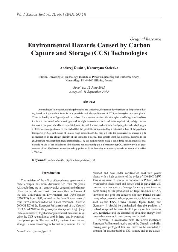
The areas of maximum concentration values of the gas
for both diameter variants are shown in Figs. 6 and 7. The
marked areas in the figures relate to CO2 concentration values of 5 (risk to human health), 10 and 20% (risk to human
life). The presented results of CO2 outflow simulation are
performed using the PHAST v.6.7 software package [13],
with an implemented Unified Dispersion Model [14],
assuming the Gaussian distribution of the concentration of
released gases in the air.
The performed analyses show that for pipelines with
diameters of up to 0.2 m and gas pressure p=15 MPa, the
range of areas with a concentration higher than 10% (i.e. a
concentration which is hazardous to the health and life of
humans and animals), reaches 75 meters and encompasses
an area of about 278 m2. For pipelines with diameters of 0.5
209
60
50
40
30
d = 0,2 m
20
10
d = 0,5 m
0
0
50
100
150
200
250
300
350
time [s]
Fig. 5. Change in CO2 concentration depending on time.
m and pressures of 15 MPa the range is 225 m, encompassing an area of 3,457 m2. The calculated sizes of the zones
presenting potential hazard to humans are comparable to the
hazard zones around pipelines transporting natural gas.
Conclusions
Fig. 3. Gas outflow from the damaged pipeline.
According to European Union requirements and directives, the further development of the power industry based
on hydrocarbon fuels is only possible with the application
of CCS technologies in power plants. These technologies
will greatly reduce carbon dioxide emissions into the
�210
Rusin A., Stolecka K.
Maximum Concentration Footprint
Study Folder: obliczenia CO2
Audit No. 19788
Model: 20 mm
Weather Category 1.5/D
Material: CARBON DIOXIDE
High: 0 M
Concentration
1875.22 m2 @ 5e+004 ppm
278.028 m2 @ 1e+005 ppm
Cloud Width (m)
33.9413 m2 @ 2e+005 ppm
Distance Downwind (m)
Fig. 6. CO2 concentration areas for a 0.2 m diameter pipeline.
Maximum Concentration Footprint
18292.4 m2 @ 5e+004 ppm
3457.53 m2 @ 1e+005 ppm
653.584 m2 @ 2e+005 ppm
Cloud Width (m)
Study Folder: obliczenia CO2
Audit No. 19788
Model: 500 mm
Weather Category 1.5/D
Material: CARBON DIOXIDE
Averaging Time: User-defined(3600 s)
High: 0 M
Concentration
Distance Downwind (m)
Fig. 7. CO2 concentration areas for a 0.5 m diameter pipeline.
atmosphere. And this, according to the current stage of
knowledge, should prevent the negative changes in climate.
On the other hand, attention should be drawn to the hazards
that these technologies involve and which could affect both
humans and the environment. Although carbon dioxide is
not considered to be a toxic gas and its slight amounts are
included in the atmospheric air, in big concentrations it can
pose a health or even life hazard to both humans and animals. Analyzing the individual stages of the CCS technology, it may be concluded that the greatest risk is created by
a potential failure of the pipelines transporting CO2. This
results from the fact that transport via pipelines is carried
out at extremely high pressures and that the pipeline diameters have to be relatively large, due to the amount of the
transported gas. Consequently, in the case of failure huge
amounts of CO2 may get into the surroundings, increasing
its concentration in the closest vicinity of the damaged
pipeline.
The hazard zones given above depend of course on the
amount of CO2 that might get into the surroundings, i.e. on
the damaged pipeline capacity. Therefore, in order to limit
the impact of such a failure, CO2 leak detectors and safety
valves connected to them should be used so that the damaged section of the pipeline can be cut off if leakage occurs.
This will limit the amount of the released gas and decrease
of the critical areas.
The estimation of zones where a significant rise in the
CO2 concentration is possible after a pipeline failure should
be made at the stage of planning the run of pipelines transporting CO2. The calculations of such zones presented in
the paper correspond to the dimensions of the pipelines and
to the parameters of the gas that may be featured by the
CCS installations to be built in Polish power plants.
Acknowledgements
The results presented in this paper were obtained from
research work co-financed by the National Center of
Research and Development in the framework of contract
SP/E/1/67484/10 – Strategic Research Program –
Advanced technologies for obtaining energy: Development
of a technology for highly efficient zero-emission coal-fired
power units integrated with CO2 capture.
�Environmental Hazards Caused...
211
References
1.
2.
3.
4.
5.
6.
DIRECTIVE 2009/31/EC of THE EUROPEAN PARLIAMENT AND OF THE COUNCIL of 23 April 2009 on the
geological storage of carbon dioxide and amending Council
Directive 85/337/EEC, European Parliament and Council
Directives 2000/60/EC, 2001/80/EC, 2004/35/EC,
2006/12/EC, 2008/1/EC and Regulation (EC) No.
1013/2006.
DEEL D., MAHAJAN K. Risk assessment and management
for long-term storage of CO2 in geologic formations –
United States Department of Energy R&D, Systemics,
Cybernetics and Informatics, 5, (1), 79, 2008.
STENHOUSE M.J., GALE J., ZHOU W. Current status of
risk assessment and regulatory frameworks for geological
CO2 storage, Energy Procedia 1, 2455, 2009
SHUTER D., BILIO M., WILDAY J., MURRAY L.,
WHITBREAD R. Safety issues and research priorities for
CCS systems and infrastructure, Energy Procedia 4, 2261,
2011.
CONDOR J., UNATRAKARN D., WILSON M.,
ASGHARI K. A Comparative analysis of risk assessment
methodologies for the geologic storage of carbon dioxide,
Energy Procedia 4, 4036, 2011.
GERSTENBERGER M., NICOL A., STENHOUSE M.,
BERRYMAN K., STIRLING M., WEBB T., SMITH W.
Modularised logic tree risk assessment method for carbon
7.
8.
9.
10.
11.
12.
13.
14.
capture and storage projects, Energy Procedia 1, 2495,
2009.
ALIE C., DOUGLAS P.L., DAVISON J.: On the operability of power plants with CO2 capture and storage, Energy
Procedia 1, 1521, 2009.
ZHANG Y., OLDENBURG C.M., FINSTERLE S., JORDAN P. Probability estimation of CO2 leakage through
faults at geologic carbon sequestration sites, Energy
Procedia 1, 41, 2009.
ELDEVIK F., GRAVER B., TORBERGSEN L.E.,
SAUGERUD O.T. Development of a guideline for safe, reliable and cost efficient transmission of CO2 in pipelines,
Energy Procedia 1, 1579, 2009.
GALE J., DAVISON J. Transmission of CO2 – safety and
economic considerations, Energy 29, 1319, 2004.
MOLAG M., DAM C. Modelling off accidental releases
from a high pressure CO2 pipelines, Energy Procedia 4,
2301, 2011.
WITKOWSKI A., RUSIN A., MAJKUT M., RULIK S.,
STOLECKA K. Comprehensive analysis of the pipeline
transportation systems for CO2 sequestration.
Thermodynamics and safety problems, 3rd International
Conference on Contemporary Problems of Thermal
Engineering CPOTE 2012, Gliwice, Poland
PHAST v.6.7 DNV Software 2010.
Yellow Book, Ed. C.J.H. Bosch, R.A.P.M. Weterings, Hague
2005.
��
 Andrzej Rusin