band applications with a reasonable LO power of 0 dBm, moderate OP1dB and high LO-to-RF suppression, compared with previously reported mixers.
4. CONCLUSION
In this article, a wide IF bandwidth up-conversion mixer has
been realized using the commercial standard bulk 90-nm 1P9M
CMOS process. Compared to the conventional double-balanced
Gilbert-cell mixer structure, the proposed mixer consists of an
active balun to avoid extra power consumption. The RCfeedback results in a phase difference below 58 and a magnitude
difference below 1 dB, from dc to 10 GHz. Moreover, the series
inductive-peaking techniques used by the integrated transformer
achieve a wide IF 3-dB bandwidth from dc to 3.8 GHz. The LO
3-dB frequency bandwidth ranges from 53 to 65 GHz. The proposed mixer is suitable for high data rate wireless applications.
ACKNOWLEDGMENTS
The authors acknowledge chip fabrication and measurement support provided by National Chip Implementation Center (CIC)
and National Nano Device Laboratories (NDL), Taiwan.
REFERENCES
1. M.C. Chen, H.S. Chen, T.C. Yan and C.N. Kuo, A CMOS Upconversion mixer with wide if bandwidth for 60-GHz applications,
Proc IEEE Silicon Monolith Integr Circuits RF Syst (2009), 1–4.
2. M. Kraemer, D. Dragomiresucu, and R. Plana, A dual-gate 60 GHz
direct up-conversion mixer with active IF balun in 65 nm CMOS,
2010 Int Conf Wireless Information Tech Syst (2010), 1–4.
3. J.C. Jeong, I.B. Yom, and K.W. Yeom, An active IF balun for a
doubly balance resistive mixer, IEEE Microwave Wireless Compon
Lett 19 (2009), 224–226.
4. H. Ma, S.J. Fang, F. Lin, and H. Nakamura, Novel action differential
phase splitters in RFIC for wireless applications, IEEE Trans Microwave Theory Tech 46 (2005), 2597–2603.
5. I. Song, J. Lee, C. Byeon, S. Cho, H. Kim, I. Oh, and C. Park,
60 GHz double-balanced drain-pumped up-conversion mixer using
90 nm CMOS, 2013 IEEE MTT-S Int Microwave Symp Dig (2013),
1–4.
6. T.M. Tsai and Y.-S. Lin, A 15.1 mW up-conversion mixer with 4.5
dB gain and 57.5 dB LO-RF isolation, Electron Lett 48 (2012), 844–
845.
7. P.S. Wu, C.H. Wang, C.S. Lin, K.Y. Lin, and H. Wang, A compact
60 GHz integrated up-converter using miniature transformer coupler
with 5 dB conversion gain, IEEE Microwave Wireless Compon Lett
18 (2008), 641–643.
C 2016 Wiley Periodicals, Inc.
V
UWB PATCH ANTENNA AND BREAST
MIMICKING PHANTOM DESIGN AND
IMPLEMENTATION FOR MICROWAVE
BREAST CANCER DETECTION USING
TIME REVERSAL MUSIC
Mamadou Hady Bah, Jing-Song Hong, and Deedar Ali Jamro
School of Physical Electronics, University of Electronic Science and
Technology of China, Chengdu 610054, China; Corresponding
author: sintaba@yahoo.com
Received 9 July 2015
ABSTRACT: In this manuscript, a small size UWB patch antenna and
a breast mimicking phantom are designed and implemented for microwave breast cancer detection using Time Reversal MUSIC. Some new
DOI 10.1002/mop
techniques are applied to the antenna in order to achieve a broad bandwidth, high gain, and also to avoid the energy radiation toward the
ground plane of the antenna. The resulting dielectric constant of the
breast phantom is relatively close to the real normal breast tissues. After
the design has been completed, some techniques of Time Reversal
MUSIC were employed to mimic the breast cancer detection. The experimental results show that both temporal and spacial images of the target
C 2016 Wiley Periodicals, Inc. Microwave
(tumor) are well represented. V
Opt Technol Lett 58:549–554, 2016; View this article online at
wileyonlinelibrary.com. DOI 10.1002/mop.29613
Key words: UWB patch antenna design; antenna broad bandwidth;
breast mimicking phantom; microwave breast cancer detection; Time
Reversal MUSIC
1. INTRODUCTION
Breast cancer is among others, one of the major diseases that
women fear the most. It is considered one of the main causes of
world width women mortality [1]. In the last decade, many
efforts have been made and still are in progress in order to overcome this issue [2]. However detection and treatment in earlier
stages remain the best hope to long-term survival from the disease [3–8].
The X-ray mammography, considered as the standard screening method for earlier breast cancer diagnosis, the results turn
out still with many limitations. Approximately up to 34% of
breast tumors are failed to be diagnosed by this method [6,7]
whereas almost 70% of the breast tumors are identified as
benign [8]. It is characterized by a high false positive and negative rate. In addition, it uses ionizing radiation and breast compression during the examination process. These drawbacks are
the most inspiring that brought many researchers to seek for a
new and promising method to complement the mammography in
the early stage breast cancer diagnosis.
Alternatively, microwave imaging is a low cost and
improved safety technology system for breast cancer imaging.
More details can be found in Refs. 5–9. Due to its wide applicability, it can be divided into passive and active microwave
imaging. Many investigations have been made for both two
techniques in the case of breast cancer detection [10]. Passive
microwave imaging referred to as radiometry [11,12] uses the
differences in temperature between healthy and timorous tissues.
For active microwave imaging, it relays upon the difference in
dielectric properties of the human tissues [4,7,13].
In the literature’s studies, the permittivity of malignant tissues (cancer) was found to be 10–20% higher than the healthy
tissues [14].
With the increase of breast cancer mortality in the recent
decades, many methods using breast phantoms have been studied and experimented in order to estimate the real breast tissues
properties [2,7,14]. The use of oil in gelatin has been implemented by Lazebnik et al. in Ref. 14. This method consists of
mixing these two materials and adding surfactant liquids. It has
been also utilized by Madsen et al. [15] in the field of ultrasound for tissues mimicking. For this study, a mixture of some
daily life use materials having different dielectric properties is
considered as breast phantom.
In microwave imaging system, the EM wave propagation
through biological tissues is characterized by some refraction
and multipath properties. This could lead the back-scattered signals to reach the detector by multipath. These conditions return
some limitations to the identification of the target location. To
overcome this issue we make use of time reversal multiple signals classification (TR_MUSIC). It has the ability to employ the
MICROWAVE AND OPTICAL TECHNOLOGY LETTERS / Vol. 58, No. 3, March 2016
549
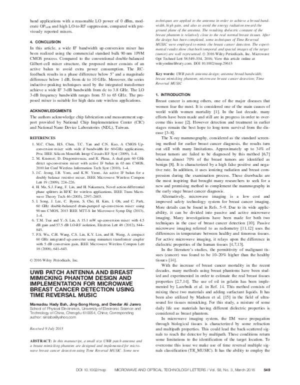
�Figure 1 (a) Parametric design; (b) fabricated antenna with reflector. [Color figure can be viewed in the online issue, which is available at wileyonlinelibrary.
com]
multipath propagation to achieve good results in target detection
such as breast cancer detection [1]. In TR_MUSIC more complex is the imaging medium more the imaging result is obvious.
As the human body has different type of tissues having different
electrical properties which make it complex, we have found that
TR_MUSIC is one the most effective methods for breast cancer
detection. However it has some limitations especially for dense
breast tissues.
In this imaging system, antenna is a very important tool
which facilitates the transmission and/or reception of the EM
waves. Ever since engineers started using microwaves for medical applications, the search for a suitable antenna has strongly
attracted their attention. Many antennas have been used in
microwave medical imaging. Among them, patch is a compact
and versatile design that is characterized by the potential advantages to be low cost, light weight, easy design, broad bandwidth
property, and has greater availability.
2. MATERIALS AND METHODS
In this manuscript, our aim is to carry out an experimental study
on breast cancer detection based on time reversal (TR_MUSIC)
method using a previously designed patch antenna and a
breast mimicking phantom. For safety proposes, the designed
antenna and breast phantom have been chosen to operate
within the range allocated by ISM (Industrial, Science and
Medical) which is from 10 MHz to 20 GHz. For this paper, all
design and simulations were performed using computer simulation technology Software (CST Microwave studio), Matlab,
and origin Pro. To confirm the results obtained through simulation, some experimental measurements are performed
bellow.
3. GEOMETRY OF THE SINGLE MONOPOLE ANTENNA
Due to the stability in the impedance bandwidth of rectangular
patch antenna compared to elliptical and circular monopoles
[16], we choose to use the rectangular shaped antenna, operating
in the UWB range 3.1–10.6 GHz authorized by FCC. The initial
dimensions of the radiating patch LP and WP are taken as k=4 at
the lower frequency point. In Figure 1 the radiating antenna
(colored in pink) is designed on top of a FR_4 substrate having
a dielectric constant of 4.6 and a height of 1.2 mm. LS 535,
WS 5 44, WP 5 24, and LP 5 17 are length and width of the substrate and the radiating patch, respectively. In its opposite face a
reduced and blended ground plane is placed. The radius of the
Figure 2 (a) Antenna array surrounding the breast model. (b) The excitation signal. [Color figure can be viewed in the online issue, which is available
at wileyonlinelibrary.com]
550
MICROWAVE AND OPTICAL TECHNOLOGY LETTERS / Vol. 58, No. 3, March 2016
DOI 10.1002/mop
�Figure 3 Compared S-parameters of the UWB antenna. [Color figure
can be viewed in the online issue, which is available at wileyonlinelibrary.
com]
blended edges is 16 mm. The side length of the square slot is
a 5 7 mm. Figure 1 illustrates the parametric design and the fabricated antenna with and without reflector. LF 510.5 is the
length of the feed-line; Lb 2.5 and Wb 5 15 are length and width
of the feed-step which also contributes to the input port matching; and finally WG 5 40 is the width of the ground. All dimensions are in millimeter (mm).
Figure 5 Ground blending effect of the antenna. [Color figure can be
viewed in the online issue, which is available at wileyonlinelibrary.com]
D2 Eðr; tÞ 2 lðrÞeðrÞ
@2
Eðr; tÞ 5 0
@t2
(1)
An electromagnetic wave is called time reversal if the wave can
propagate backward, in such case the signal would refocus to the
point source. In another words, Time Reversal is a new technique
which satisfies the reciprocity theorem EðtÞ5Eð2tÞ; meaning that
if Eðr; tÞ is a solution of Eq. (1), then the existence of another solution will be observed so-called Time Reversed Eðr; tÞ5Eðr; 2tÞ .
For simplicity, here we consider the electromagnetic wave equation in a uniform and loss-free medium.
In this equation, Eðr; tÞ is the electric field; ~
r is the vector position; l; e are permeability and permittivity,
respectively.
The reciprocity theorem governing this wave equation allows
the scattered wave to reverse and propagate backwards to the
original source. The TR wave would focus at the point source
regardless of the nature of the medium. The basic idea about
TR consist of recording the different received wave signals
using an array of transducers, time reverse, and send it back to
the original point source. It can exploit the multipath effect to
achieve good results [17].
TR microwave imaging techniques use the multi-static data
matrix (MDM). Different imaging methods for microwave breast
cancer imaging are investigated in Refs. 3,4,17 using Time
Figure 4 Compared Gain of the antenna. [Color figure can be viewed
in the online issue, which is available at wileyonlinelibrary.com]
Figure 6 Slot effect of the monopole antenna. [Color figure can be
viewed in the online issue, which is available at wileyonlinelibrary.com]
4. TR_MUSIC AND MULTI-STATIC IMAGING ALGORITHM
DOI 10.1002/mop
MICROWAVE AND OPTICAL TECHNOLOGY LETTERS / Vol. 58, No. 3, March 2016
551
�K5UuV H
(6)
After substituting the singular value decomposition, K,
into the time reversal operator defined as T5K H K; then we
will getK5UuV H VuUH where the upper script H denotes
conjugate transpose operation. Here U and V are both unitary
matrixes; so the finally time reversal operator can be deduced
as T5u2 :
For DORT, every eigen value of u2 signifies the presence of
the cancer in the investigated region. The back propagated corresponding eigenvectors facilitate the identification of the targets
in that region. There is a strong relationship between the eigenvectors (v) and the Green’s (g) function vector of the medium
[11,18] as shown in (11) .
vm ðxÞ � eju
Figure 7 The dielectric constant of the breast phantom
Reversal. Among the well-known methods, DORT and TR
MUSIC are based on either the eigen values or its equivalent
singular value decomposition of the MDM matrix. Here, we propose the use of Time Reversal multiple signals classification
(known as TR-MUSIC) technique to estimate the location of a
tumor in a breast phantom. For that, let us consider an N
antenna elements located at rj. To facilitate the localization of
M targets in a two dimensional plane, we apply an excitation
signal ej (x) to the jth element of the antenna array with j 5 1,
2, 3, . . . N. ej (x) is the excited electric field with respect to the
frequency domain. The electric field, after being propagated in
the region under investigation, the scattered energy by the Mtarget is recorded by the lth element of the array and it can be
expressed as
M
X
ESlj 5
GðXm ; rl ; xÞsm ðxÞGðrl ; Xm ; xÞej ðxÞ
(2)
m51
g� ðxm Þ
kgðxm Þk
(7)
where u is the phase arising from singular value decomposition
and upper script star denotes conjugate operation. Consequently,
the DORT imaging function that utilizes the signal subspace can
be formulated as
IDORT ðrÞ5
M
X
2
jhv�n jgðr; xÞij
(8)
n51
Due to the orthogonality between noise and signal subspaces,
time reversal can make use of the singular value decomposition
of the multi-static data matrix to separate them. Then the scattering object located at r will be estimated by the time reversal
MUSIC pseudo-spectrum formulated in Eq. (9).
ITR
MUSIC ðrÞ5 X
N
1
2
This condition is satisfied only when the term hv�n jgðrÞi is set
to be null. Here v�n stands for the n eigenvectors and gðrÞ is the
vector Green’s function.
where sm (x) is the scattering potential, representing the backscattering strength as a function of angular frequency; Xm and rj
represent the location of mth target, and the jth receiving element; k is the wave propagation constant and G is the background Green’s function of the medium. For simplicity, in the
following section, we omit the frequency term in the mathematical formulation. The l,jth element of the multi-static data matrix
can be written as
M
X
Klj 5ESlj 5
sm gr ðXm ÞgTt ðXm Þ
(3)
m51
where the upper script T denotes transpose operation; gr and gt
are vectors Green’s function for transmission (subscripts t) and
reception (subscripts r) respectively. gr and gt can be define as
gr ðXm Þ5½Gðr1 ; Xm Þ; Gðr2 ; Xm Þ; :::; GðrN ; Xm Þ�
(4)
gt ðXm Þ5½GðXm ; r1 Þ; GðXm ; r2 Þ; :::; GðXm ; rN Þ�
(5)
By taking into account the reciprocity theorem in the propagation medium, the MDM becomes symmetric and can be
express as Klj 5Kjl . The singular value decomposition, K, can be
represented as
552
(9)
jhv�n jgðrÞij
n5M11
Figure 8 Time reversal focused signal
MICROWAVE AND OPTICAL TECHNOLOGY LETTERS / Vol. 58, No. 3, March 2016
DOI 10.1002/mop
�Figure 9 The location of the tumor (cancer) inside the breast phantom at 6.85 GHz. [Color figure can be viewed in the online issue, which is available
at wileyonlinelibrary.com]
5. EXPERIMENTAL SETUP
For our experimental study, four antennas have been considered, symmetrically placed around the breast phantom that has
been predesigned. The antennas lie on a circle with a radius
of 100 mm. So that the distance between two symmetric
antennas is 200 mm. An image illustrating the experimental
set up is shown in Figure 2. During the experiment, these
antennas play both the role of transmitting and receiving;
however only one antenna transmit at a time. In the process,
the antenna elements (numbered from 1 to 4) around the
breast phantom transmit a short pulse signal into the imaging
medium, after its propagation, the backscattered signals are
recorded by the receiving antennas and then retransmitted
back to the original source. The more the reversed signal tends
to the point source the more the signal is compressed. The
maximum amplitude of the time reversed signal is observed at
the point source.
In Figure 2, the breast phantom is composed of three different materials: corn flour, soy bean oil, and water in a ratio of
6.5:2:1.5. These materials have been chosen because when
they are mixed in this ratio, it displays a dielectric constant
similar to that of the real normal breast tissues. In the case of
the breast cancer (tumor), due to the high dielectric constant of
the malignant tissues (cancer or tumor), mineral water has
been considered, put in a unit cell glass and imbedded in the
phantom. The top of the cell glass was covered with a wood
stick (see Fig. 2).
6. SIMULATION AND EXPERIMENTAL RESULTS
This section shows a good agreement between the simulation
and measured results. In Figure 3, the results illustrate a return
loss less than 210 dB over the entire frequency range. As
expected, a broad bandwidth is obtained for both simulated and
measured results. The little variation observed in the results is
due to some errors acquired during the port welding and the surrounding environment in the experiment. In the parametrical
design figure, a slot is made on the radiating patch where less
electric current distribution is observed. A diamond structure is
DOI 10.1002/mop
cut out in order to control the surface current and match the low
frequency. In the opposite plane, a reduced ground plane has
been adopted.
In this antenna structure, the length of the ground is reduced
to k=10 over a width of less than k=2 at the low operating frequency; a blending edge is applied to the upper edges of the
ground. It is well known that a microstrip patch antenna fully
ground bounded is more directional; however due to the confinement of the fringing fields in between the radiating patch
and the ground plane in that case, the bandwidth of the antenna
could be affected, leading to a narrow bandwidth of the radiator
as well as increasing the size of the antenna. By taking into
account the relationship between the skin depth and the operating frequency [see Eq. (10)], some techniques are applied to the
design in order to achieve good penetration depth and high resolution as well.
kp 5
c
sffiffiffiffiffiffiffiffiffiffiffiffiffiffiffiffiffiffiffiffiffiffiffiffiffiffiffiffiffiffiffiffiffiffiffiffiffiffiffiffiffiffiffiffi
qffiffiffiffiffiffiffiffiffiffiffiffiffiffiffiffiffiffiffiffiffiffiffiffiffiffiffiffi
�
2
11 e0r =er 21
2pf 2er
(10)
The blending edges of the ground together with the slot on
the radiator contribute to the improvement of the bandwidth
and the miniaturization of the antenna as well. Figure 4
shows up the simulated and measured high gain. The effects
of blending the edges of the ground plane and the slot in the
middle of the radiator are depicted in Figures 5 and 6,
respectively.
Below are shown the dielectric constant of the breast phantom (Fig. 7) and the resulting waveform with good temporal
focusing signals (see Fig. 8). For this breast phantom, we have
been able to achieve a relative permittivity between 9 to 12
which is relatively close to the real normal breast tissues as presented in Refs. 7,19. This is due to the low water content in it.
In Figure 8, the resulting waveform explains the ability of the
Time Reversal technique to refocus the signals from the receiving positions back to the source. In a more realistic approach, a
comparison between the simulated and experimental results is
MICROWAVE AND OPTICAL TECHNOLOGY LETTERS / Vol. 58, No. 3, March 2016
553
�carried out in this study using TR-Music algorithm formulated
in Eq. (9). A good estimation of the target location is shown in
Figure 9. Refer to Figure 2, we can see that the target is located
in the middle of the imaging medium with a set of antennas
placed around the breast.
7. CONCLUSION
Through this manuscript, a UWB patch antenna operating in
the range of 3.1–10.6 GHz (according to FCC) is designed and
implemented for breast cancer detection using time reversal
MUSIC. For a further understanding approach, some comparisons are conducted between the results obtained from simulation and measurement. One of the big advantages of this
antenna is that its size has been reduced without the use of
high dielectric constant or high frequency as employed in Ref.
10. As characteristic of this design, a broad bandwidth and a
relatively high gain are achieved. In microwave breast cancer
imaging, the commonly used technique is to rotate the transmitting antenna around the breast and this is to facilitate the
cancer (tumor) detection. As the target is located in front of
the transmitting antenna, we need to focus almost all the radiated energy in forward direction. By placing the reflector in
the back side of the antenna, it contributes to improve not only
the gain but the directivity of the antenna as well. This experimental test was carried out in free space as depicted in Figure
2. The designed antenna can be used for multiple applications
using broadband in the UWB frequency range from 2 to
12 GHz. A dielectric constant relatively close to the real normal breast tissue is achieved, refer to Refs. 7,19. In this experiment, all materials used are safe, non-toxic even through
inhalation. The waveform in Figure 9 shows up a very narrow
peak at the focusing point, meaning that the time reversed signals from the receiving points are well focused. This will facilitate the detection and localization of the cancer (tumor) from
the breast. Figures 9(a) and (b) explain about the capability of
the antenna to transmit and receive a narrow pulse signal,
which is very important in target detection such as breast cancer detection through medical imaging. In Figure 9(b), the
measured result presents some noise, this is due to the migration of the water and oil from top to the bottom of the bottle
during one week deposit after the breast phantom has been
modeled.
From this research, we can conclude that even though
TR_MUSIC has a lot of advantages in breast cancer detection,
the experimental work remains with some limitations such as
carrying out an experiment with highly dense breast and a
breast mimicking phantom resulting from mixed materials of
different dielectric properties. In simulation it would be easier
to achieve good results through breast cancer detection. Finally
we found it very challenging to achieve a dielectric constant
relatively close to the breast tissues by mixing non-chemical
materials, with different dielectric constants. Also we think
there is a need of a more advanced method to complement the
limitation of Time Reversal MUSIC in the case of very dense
tissues.
ACKNOWLEDGMENTS
This work was supported by the National Natural Science Foundation of China (No. 61172115 and No. 60872029); the HighTech Research and Development Program of China (No.
2008AA01Z206); the Aeronautics Foundation of China (No.
20100180003); and the Fundamental Research Funds for the
554
Central Universities (No.
9140A07030513DZ02098.
ZY-GX2009J037)
and
Project
REFERENCES
1. M. Sajjadieh, F. Foroozan, and A. Asif, Breast cancer detection
using time reversal signal processing, In: IEEE 13th International
Multioptic Conference, INMIC 2009, 2009.
2. N. Nadine Joachimowicz, C. Conessa, T. Henriksson, and B.
Duch^ene, Breast phantoms for microwave imaging, IEEE Antennas
Wireless Propag Lett 13 (2014), 1333–1336.
3. M.D. Hossain and A.S. Mohan, Breast cancer localization in three
dimensions using time reversal DORT method, In: IEEE Antennas
and Propagation (ISAP), Chicago, IL 2012.
4. Y.W. Jin, J.M.F. Moura, and Y. Jiang, Breast cancer detection by
time reversal imaging, In: IEEE Biomedical Imaging: From Nano to
Macro, ISBI 2008, 2008.
5. W. Shao and R.S. Adams, Two antipodal vivaldi antennas and an
antenna array for microwave early breast cancer detection, Microwave Opt Technol Lett 55 (2013), 670–674.
6. P.T. Huynh, A.M. Jarolimek, and S. Daye, The false-negative mammogram, Radiograph 18 (1998), 1137–1154.
7. E.C. Fear, X. Li, S.C. Hagness, and M.A. Stuchly, Confocal
microwave imaging for breast cancer detection: Localization of
tumors in three dimensions, IEEE Trans Biomed Eng 49 (2002),
812–822.
8. J.G. Elmore, M.B. Barton, V.M. Moceri, S. Polk, P.J. Arena, and
S.W. Fletcher, Ten-year risk of false positive screening mammograms and clinical breast examinations, New Engl J Med 338
(1998), 1089–1096.
9. E.C. Fear, S.C. Hagness, P.M. Meaney, M. Okoniewski, and M.A.
Stuchly, Enhancing breast tumour detection with nearfield imaging,
IEEE Microwave Mag 3 (2002), 48–56.
10. K.L. Carr, Microwave radiometry: Its importance to the detection of
cancer, IEEE Trans Microwave Theory Tech 37 (1989), 1862–1869.
11. B. Bocquet, J.C. van de Velde, A. Mamouni, Y. Leroy, G. Giaux, J.
Delannoy, and D. Del Valee, Microwave radiometric imaging at
3 GHz for the exploration of breast tumors, IEEE Trans Microwave
Theory Tech 38 (1990), 791–793.
12. S.S. Chaudhary, R.K. Mishra, A. Swarup, and J.M. Thomas, Dielectric properties of normal and malignant human breast tissues at
radiowave and microwave frequencies, Indian J Biochem Biophys
21 (1984), 76–79.
13. J. Surowiec, S.S. Stuchly, J.R. Barr, and A. Swarup, Dielectric properties of breast carcinoma and the surrounding tissues, IEEE Trans
Biomed Eng 35 (1988), 257–263.
14. M. Lazebnik, E.L. Madsen, G.R. Frank, and S.C. Hagness,
Tissue-mimicking phantom materials for narrowband and ultrawideband microwave applications, Phys Med Biol 50 (2005),
4245–4258.
15. E.L. Madsen, J.A. Zagzebski, and G.R. Frank, Oil-in-gelatin dispersions for use as ultrasonically tissue-mimicking materials, Ultrasound
Med Biol 8 (1982), 277–287.
16. Abbosh and M.E. Bialkowski, Design of ultra-wideband planar
monopole antennas of circular and elliptical shape, IEEE Trans
Antennas Propag 56 (2008), 17–23.
17. M.E. Yavuz and F.L. Teixeira, Ultra wideband microwave sensing
and imaging using time-reversal techniques: A review, Remote Sens
9 (2009), 466–495.
18. M. Delwar Hossain, F. Yang, M.J. Abedin, and A. Sanagavarapu
Mohan, Time reversal microwave imaging for the localization and
classification of early stage breast cancer, In: Proceedings of
the Asia-Pacific Microwave Conference, 2011, IEEE, Australia,
p, 477
19. S.M. Salvador and G. Vecchi, Experimental tests of microwave
breast cancer detection on phantoms, IEEE Trans Antennas Propag
57 (2009), 1705–1712.
C 2016 Wiley Periodicals, Inc.
V
MICROWAVE AND OPTICAL TECHNOLOGY LETTERS / Vol. 58, No. 3, March 2016
DOI 10.1002/mop
�
 Mamadou hady Bah