International Journal of Architectural Heritage
Conservation, Analysis, and Restoration
ISSN: 1558-3058 (Print) 1558-3066 (Online) Journal homepage: http://www.tandfonline.com/loi/uarc20
The effect of inclination of scarf joints with four
pins
Petr Fajman & Jiří Máca
To cite this article: Petr Fajman & Jiří Máca (2018): The effect of inclination of scarf joints with four
pins, International Journal of Architectural Heritage, DOI: 10.1080/15583058.2018.1442520
To link to this article: https://doi.org/10.1080/15583058.2018.1442520
Published online: 30 Mar 2018.
Submit your article to this journal
View related articles
View Crossmark data
Full Terms & Conditions of access and use can be found at
http://www.tandfonline.com/action/journalInformation?journalCode=uarc20
INTERNATIONAL JOURNAL OF ARCHITECTURAL HERITAGE
https://doi.org/10.1080/15583058.2018.1442520
The effect of inclination of scarf joints with four pins
Petr Fajman and Jiří Máca
Faculty of Civil Engineering, Czech Technical University in Prague, Praha, Czech Republic
ABSTRACT
ARTICLE HISTORY
During the renovation of roof trusses and roof structures, damaged wood must be replaced with
new wood. To keep the original material adjustment slab joints can be used. Unfortunately, this
type of joint has not been observed from the structural perspective. The shape of the joint, the
inclination of its faces, the type and the number of connectors still represent an unknown area. A
simplified analytical model is briefly derived in the article and the effect of the face inclination is
solved. The results obtained from experiments are compared with the results from the model.
Received 7 January 2018
Accepted 8 January 2018
1. Introduction
Scarf joints are frequently used in the reconstructions
of historical structures. In choosing the shape, the type
of joint, and the number of connectors, the knowledge
of their behavior is essential. In the literature, we primarily read about structural principles, but not much is
known about their structural action. Different points of
view interfere with each other in the design of the scarf
joint. It is, for example, the joint labor intensity and
accuracy, its length, historical aspect, and structural
action. The above views are often controversial and a
compromise must be sought.
The analytical design of a joint with four pins is a
follow-up to preceding designs of a joint with one,
two, and three connecting pieces (Fajman 2014;
Fajman and Máca 2014, 2015a, 2015b, 2017;
Kunecky et al. 2014). The joint is characterized by
the fact that both the connecting pieces and the
abutment of the faces at the scarf joint’s end participate in the transfer of load. The distribution of forces
in the scarf joint and the estimation of a change in
the stiffness of a member with a scarf joint against a
member without a scarf joint represented an interesting issue to investigate. The important finding
obtained was that if a lower number of connecting
pieces is used a change in the inclination of the faces
plays a significant role in the joint behavior. To put it
plainly, a lower inclination implies that the faces lean
against each other more giving the joint a higher
load-bearing capacity, but the long length of the
joint is a disadvantage. In terms of practicality, on
the contrary, a 90° inclination (perpendicular faces)
KEYWORDS
Experimental; numerical;
oblique; pin; scarf joint;
stiffness
represents the easiest solution. A compromise is
sought in using the inclination of 45°. The recent
technology used for extending members is via a
scarf with multiple pins; see Figure 1. The designers
are convinced that the greater the number of pins the
higher the joint stiffness. The experiments
(Arciszewska-Kędzior et al. 2015a, 2015b; Kunecky
et al. 2015) and calculations (Fajman 2014; Fajman
and Máca 2014; 2015a, 2015b, 2017) performed, however, indicate that the increasing number of pins does
not lead to an increased load-bearing capacity of the
bar; for this reason, the article focuses on a scarf
joint which minimises the number of connecting
pieces to 4. The design and introduction of simplifying assumptions is based on the knowledge obtained
from joints with 1, 2, and 3 connectors.
Numerous experimental tests (ArciszewskaKędzioret et al. 2015a, 2015b; Kunecky et al. 2015)
and FEM calculations (Kunecky et al. 2014) have been
carried out within the Design and Assessment of
Wooden Carpenter’s Joints of Historical Structures
project in the last years, and several computational
programmes based on theoretical models have been
compiled by the authors. The results may serve for
drawing conclusions which can help in the design of
the respective joints.
2. Scarf joint
If a timber structure shows lowered reliability, it must
be repaired. In the case of repairing a historical structure, as much original material must be preserved as
CONTACT Petr Fajman
fajman@fsv.cvut.cz
Faculty of Civil Engineering, Czech Technical University in Prague, Thákurova 7, Praha, Czech Republic.
Color versions of one or more of the figures in the article can be found online at www.tandfonline.com/uarc.
© 2018 Taylor & Francis
2
P. FAJMAN AND J. MÁCA
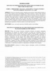
Figure 1. Repair of a ceiling at Kost Castle—performed by Hrdlicka.
(a)
Part 1
(b)
pins
Part 2
Figure 2. (a) Halved scarf joint with pins and (b) oblique scarf joint with pins.
possible (Branco, Piazza, and Cruz 2010; Piazza and
Riggio 2007). This can best be achieved by using a
scarf joint; see Figure 1.
A typical lapped scarf joint is drawn in Figure 2.
Depending on its design, there are halved scarf joints or
oblique scarf joints. There is also a scarf joint with an
inside tenon where one part contains a central tenon
and the other two scarfs. According to the connectors
used, there are scarf joints secured by wooden pins,
steel bolts, wooden dowels, or their combinations
(Fajman 2014; Fajman and Máca 2014; 2015a, 2015b,
2017).
One of the principal still open questions is the effect
of the inclination of faces on the scarf’s load-bearing
capacity. This issue was previously analysed for the case
of a scarf with one pin in the middle (Fajman 2014;
Fajman and Máca 2014). In that case, with only one
pin, the results imply that a smaller inclination is
structurally more favourable for the respective joint,
but, on the other hand, it extends the scarf length.
Considering manufacturing procedures, the face inclination of 45° appeared the most convenient, showing
also sufficient load-bearing capacity in the structural
perspective. In practice, however, a scarf joint with
multiple connecting pieces is preferred. The most common design is a scarf with 4 pins or bolts in which the
effect of the inclination of faces on the load-bearing
capacity has not been investigated yet and whose design
is presented below.
3. Structural action
An important aspect for an easy design of a scarf joint
is the possibility of simplifying its spatial action into a
simpler problem. Under vertical loading, scarf joints
produce eccentric forces, exerting a bending moment,
which bends the structure perpendicular to the loading
plane. At the same time, they exert a twisting moment
in the scarf area. If the structure’s movement in the
INTERNATIONAL JOURNAL OF ARCHITECTURAL HERITAGE
3
direction perpendicular to the loading plane is prevented, the structure can be simplified into a 2D problem. This condition is fulfilled, e.g., in roof truss
beams, which are held by decking or by a soffit. In
roof truss girders, in turn, the tensile normal force
mostly helps to stabilize the structure.
The design of a scarf joint can be based on structural
principles (Piazza and Riggio 2007), a computation
using the finite-element method (Kunecky et al.
2015), a simplified theoretical model (Fajman 2014;
Fajman and Máca 2014; 2015a, 2015b, 2017), or experiments (Arciszewska-Kędzior et al. 2015b; Branco,
Piazza, and Cruz 2010; Kunecky et al. 2015; Milch
et al. 2014, 2017; Sangree and Schafer 2009).
the scarf faces, which exerts a friction force Vai = Nai μi,
where μi is the friction coefficient. The force distribution between the face and the pins depends on multiple
factors; see Eqs. (1) and (2) (for more detail see Fajman
and Maca 2015a, 2015b, 2017):
N1 ¼ Na1 sin α1 þ μ1 cos α1 ;
3.1 Halved scarf joint
where Ni, Vi are horizontal and vertical forces in the
faces, αi is the angle of oblique faces (see Figure 4).
Three equilibrium conditions—two force conditions
in horizontal and vertical directions (3) and the
moment condition (4)—can be defined:
X
Nf þ N1 þ N2 þ
Nki ¼ 0 ;
This scarf joint is easy to make, but the precise seating
of its vertical surfaces cannot be guaranteed there. In
structural terms, however, even in the case of a perfect
fitting of the vertical surfaces, it seems less suitable than
the oblique scarf joint. All load is initially only transferred by the connectors (see Figure 3), but, later, also
by the abutment in the upper part of the face. The force
acting in the pins can be substituted by two components, Nki, Vki. The respective structural system is statically indeterminate where the degree of
indeterminateness depends on the number of
connectors.
N2 ¼ Na2 ðsin α2 μ cos α2 Þ;
V1 ¼ Na1 cos α1 þ μ1 sin α1
V2 ¼ Na2 ðcos α2 þ μ sin α2 Þ
ðcos α1 þ μ1 sin α1 Þ
¼ N1 k1 ;
ð sin α1 þ μ1 cos α1 Þ
ð cos α2 þ μ2 sin α2 Þ
¼ N 2 k2
V2 ¼ N2
ðsin α2 þ μ2 cos α2 Þ
V1 ¼ N1
i¼1;4
N1 k1 þ N2 k2 þ
In manufacturing, the seating of inclined surfaces onto
each other must be secured so that they can participate
in the structural action. All load is transferred by the
scarf faces and connectors; see Figure 4. The forces in
the connectors are assisted by the normal force Nai in
N1
h
N2
Nk1
V1
Vk1
Nk3 V2
Vk3
Nk2
Nk4
Vk2
Vk4
Figure 3. Forces participating in load transfer.
Mf
Nf
Na1
N1
h
_
Mf
o:
V1 Va1
Vf
Figure 4. Forces participating in load transfer.
1
Vk2
Vki þ Vf ¼ 0
Vf xf þ
X
Ni z i
i¼1;2
þ
(3)
X
Nki :zi
X
Vki :xi ¼ 0:
X
i¼1;2
Ni ki xi
(4)
i¼1;4
The unknown quantities in the above relations are
the magnitude of the forces in pins Nki and Vki, and
the magnitude of compressive forces Ni in the scarf
faces. The origin of the forces in the faces can be
obtained from experiments; however, a small change
in the origin has no influence on the results. This
implies that there are ten unknown quantities for
three equilibrium conditions (3, 4). In this way,
only three unknown quantities will remain, which
can be identified by means of the condition for the
scarf continuity. The force method with seven
unknown quantities, e.g., the force Ni and the horizontal and vertical force in the pins Nki Vki, can be
used.
Nk1
Vk1
X
(2)
i¼1;4
i¼1;4
3.2 Oblique scarf joint
(1)
x
Nk2
N2
Vk3
Nk3
Nk4
z
Vk4
2
Va2 Na2
V2
4
P. FAJMAN AND J. MÁCA
Part I
1
disconnected
1
X2
z1
11
1
1
Spring
connection
1
X3
Part II
1
connected
1.k1
X1
1.k1
X1.k1
Part I
X4
zk3
z2
X5
2
X7
X6
2
Part II
Figure 6. Forces for δ11.
Figure 5. Virtual set up with forces in Part 1.
The part of a scarf between points 1 and 2 is shown in
Figure 5. It is labeled I, with unknown forces X1, X1k1, X2
to X7 exerted in the disconnection with Part II. A similar
scheme also applies to Part II. The choice of a real
structure (RS structure without forces Xi and with loading) and a virtual structure (VS structure with forces Xi
and without loading) is enabled in various ways, e.g., by
disconnecting the parts shown in Figure 5.
In order to calculate the yield coefficients, it is
necessary to compile the moments from the loading
Mf and the axial force Nf on RS and Mi, Ni from Xi
on VS. In the connection part, there is a mutual zero
shift perpendicular to the face plane, then a zero shift in
the pin with a potential shift due to its stiffness.
The conditional equation for shifts in the face
describes the deformation at point 1 between Parts I
and II due to the force effects; see Figure 5:
X
δi ¼
Xj δij þ δijr þ δif ¼ 0;
(5)
j¼1;7
By analogy, this holds for the deformation in positions X2 to X7.
The symbols are
ð
Mi Mj Ni Nj
1
dx ; δiir ¼ 1
þ
δij ¼
;
kik2
EI
EA
Nk2;j
Mk2;j
δijr ¼ Nk2;i
þ Mk2;i
;
kuk2
kφk2
ð
Nk2;f
Mk2;f
Mi MF Ni NF
þ
dx þ Nk2;i
þ Mk2;i
:
δiF ¼
kuk2
kφk2
EI
EA
(6)
The conditional equation for the shift in the face δ11
includes the deformation at point 1 between Parts I and
II, due to the effects of the force X1, see Figure 6.
A = bh/2, or I = bh3/24 is the area, or the moment of
inertia, of the cross section of the scarf, and k is the effect of
pin yielding. The pin stiffness can be calculated or obtained
by experimental methods. In the case of the pin, the stiffness
refers to the horizontal and vertical stiffness ku; see Figure 7.
V
U= ku
v=1
u=1
V= kv
Figure 7. Plotted stresses and deformations of the peg central
line.
4. Comparison of experimental and numerical
results
The set-up defined for the experiment took into
account the results of previous experimental campaigns
and calculations. Based on the collected experience and
knowledge, the basic recommendations that were
adopted in the scarf joint design were:
face inclination of 90° (normal) or 45° (inclined);
scarf joint length ranging between 3h–7h; and
● distances of connectors must be at least 7Ø from
the face.
●
●
The geometry of the tested beam is displayed in
Figure 8. Beams were tested in a three-point bending test in the laboratories of the Institute of
Theoretical and Applied Mechanics in Prague,
Czech Academy of Sciences. For more details, see
Arciszewska-Kędzior et al. 2015b; Kunecky et al.
2015. Four groups of specimens were tested. Beams
with a halved scarf joint (normal face), beams with
an oblique joint (inclined face), beams with an
inclined face under reverse loading, and beams
without any joint. The modulus of elasticity and
tensile stress in bending were obtained during the
tests.
INTERNATIONAL JOURNAL OF ARCHITECTURAL HERITAGE
5
1470
F
1000
b= 200
h= 240
45°
800
1370
830
3000mm
L= 6000mm
Figure 8. Tested beams and scarf joints—halved scarf with normal face (upper) and oblique scarf with inclined face (lower).
4.1 Load-bearing capacity—first limit state
The load-bearing capacity of the joint depends on the failure modes which were obtained from several dozen experiments with a four-pin wooden joint. The most common
failure mode was the face splitting—see Figure 9 on the left,
then the pin failure; see Figure 9 on the right, or a failure
around the pin, and, last but not least, the failure due to
tension in the weakened cross section.
In the joint with steel pins, the failure occurs by
the tear of wood across the grain—experimentally
verified during comparative tests; see Figure 10
(Fmax = 27.1 kN, Flin = 18 kN for a 200/240 section),
Figure 9. Failure of a tested beam with four pins.
Figure 10. Resulting failure of a joint with steel pins under three-point bending load.
P. FAJMAN AND J. MÁCA
6
Kędzior et al. 2015b; Kunecky et al. 2015). The
value is calculated using the formula σ = M/Wel
where M = F.L/4 + g.L2/8 and Wel = bh2/6,
F = 34,7 kN is taken from the last row of Table 1.
and, simultaneously, rigid steel pins locally indent the
material, which supports crack initiation.
Assumptions for numerical analysis are as follows.
The modulus of elasticity Eo,mean = 9.45 GPa was
obtained from the experiments (ArciszewskaKędzior et al. 2015b; Kunecky et al. 2015) with
a beam without a joint. The value is calculated
using the formula E = F/(L3/(48.I]+L/(5/6.
A.0,06)/4)/w, where values Flin = 11,25 kN,
wlin = 24 mm are taken from the last row of
Table 2, A is the area and I is the moment of
inertia of the beam cross-section, the shear
modulus G = 0.06.E; see (Eurocede 5, 2011).
The obtained value of the modulus of elasticity
corresponds the value of C20 class wood in
Eurocode 5 (Eo,mean = 9.5 GPa).
● The limit force in the face (M1) is derived in the
form V = A.fck90 = 0.5.l.b/2.fck90, where l is the
distance of the connector from the face, besides,
the effect of seasoning splits is considered at a
value of 0.5, which is in agreement with experiments on beams stored under standard moisture
conditions with dimensions used in construction
practice, b is the width of the beam, and fck90 is the
strength perpendicular to the grain.
● The maximum loading of the pin and longitudinal
beam splitting (M2) is identified from the experiment (Milch et al. 2017) and depends on the pin’s
diameter and material and the beam’s material—
for a wooden pin with a diameter of 24 mm,
Fx = 5.8 kN, Fz = 3.25 kN.
● The tensile stress in bending (M3) fmk = 27,5 MPa
was obtained from experiments (Arciszewska●
Table 1. Comparison of beam stiffness and failure modes.
Experiment[7,8]
k lin
F lin (kN)
(F max) (kN/m)
18
365
(27.1)
24.7
476
(32.7)
18
318
(26.3)
34,7
467
(44.2)
Normal face
Inclined face
Inverse loading
Without a joint
Calculation for [C20]
failure
mode
M2
F lin
(kN)
14.0
k lin
(kN/m)
381
failure
mode
M2
M1,
M2
M2
22.5
420
M1
13.5
311
M2
29.5
(44.2)
474
F
Normal face
Inclined face
Inverse loading
Without a joint
Calculation for C20
lin (kN) w lin (mm) F lin (kN) w lin (mm)
11.25
30
11.25
29.5
11.25
24
11.25
26.8
11.25
35
11.25
36.1
11.25
24
11.25
23.8
4.2 Deflection—second limit state
The maximum short-term deflection for floor structures can be considered at a value of wmax = l/
250 = 24 mm. The load corresponding to this deflection
value in the case of a beam without a scarf was applied
to beams with scarf joints. In this way, the deflection
increment due to the joint can be identified.
Table 2 presents the results measured during the
experiments performed by (Arciszewska-Kędzior et al.
2015b; Kunecky et al. 2015) and the results calculated
from the theoretical model developed, assuming a value
of the load applied of F lin = 11.25 kN.
For wooden pins, the agreement of the calculation
with the experiment is sufficient for their application in
practice. The table compares beams with a scarf joint
against a reference beam without a scarf. This allows a
simple design of the deflection of a beam with a scarf
joint in practice. One just needs to calculate the deflection on the beam without a scarf joint and, successively,
multiply the calculated deflections by the correction
coefficient. The value of the correction coefficient for
the tested structure is between 1.1 and 1.2.
5. Discussion over results
Based on the experiments and theoretical analysis we
can say the following.
Table 2. Comparison of linear deformations.
Experiment [7,8]
Table 1 presents the forces and failure modes
obtained from the experiment and the calculation.
Due to the fact that a linear model is used, the force
is labelled Flin. An important finding is that the calculation yields a lower load-bearing capacity than the linear
value in the experiment, which is on the safe side. In
normal faces, the precision rate and the pushing of
faces onto each other are important. In a non-precise
connection, the joint behaves as a contactless joint and
all forces are only transferred by pins similarly to
inverse loading.
The results obtained by the calculation of different
geometries assumed for the scarf joints studied are
very close to the ones measured during
experiments.
● Inclined faces have a favorable effect on the joint
behavior. The angle of 45° is a good compromise
●
Difference
%
1.7
−11.7
−3.2
0.8
INTERNATIONAL JOURNAL OF ARCHITECTURAL HERITAGE
between the static load-bearing capacity of the
joint, its length, and labor intensity.
● The load-bearing capacity criteria of the computational model limit the load-bearing capacity by
80–90% of the linear values obtained by
experiments.
● The scarf joint’s most frequent failure is by the
splitting of its ends and at the point of a seasoning
split. Here, the load-bearing capacity can be
increased by means of vertical screws through
the cracks (M2).
● If the limit state of serviceability is crucial, the
deflection of a beam without a scarf can be easily
recalculated for a beam with a scarf.
6. Conclusions
The adjustment joint is a convenient means for use in
repairs of historic beams. The joint retains the original
shape of the structure and can be fabricated to be nearly
invisible. In structural terms, the stiffness of a repaired
structure is nearly the same as the original one. This is an
excellent feature in structures where the second serviceability limit state is crucial. The load-bearing capacity can
be increased by the inclination of faces and their mutual
abutment. Using an inclination of faces of 45°, the loadbearing capacity can be increased by up to 50% against a
joint with perpendicular faces. The presented analytical
model describes the linear joint behavior very well. To
determine the joint load-bearing capacity experimentally
obtained partial load-bearing capacity values of connecting pieces, including their failure modes, are necessary.
These values can subsequently be introduced in the theoretical model and the forces obtained compared against
them. The safety level is then selected in compliance with
standards.
Funding
The article was written with support from the Ministry of
Culture’s project NAKI grant project – DF12P01OVVOO4 –
Design and Assessment of Wooden Carpenter’s Joints of
Historical Structures.
References
Arciszewska-Kędzior, A., J. Kunecký, and H. Hasníková.
2015a. Mechanical response of a lap scarf joint with inclined
faces and wooden dowels under combined loading.
Structural Health Assessment of Timber Structures.
Proceedings of the International conference on Structural
7
health assessment of timber structures, SHATIS’15, Vol. 1,
201, 849–858. Wrocław: Dolnośląskie Wydawnictwo
Edukacyjne.
Arciszewska-Kędzior, A., J. Kunecký, H. Hasníková, and V.
Sebera. 2015b. Lapped scarf joint with inclined faces and
wooden dowels: Experimental and numerical analysis.
Engineering Structures 94 (July):1–8. doi:10.1016/j.
engstruct.2015.03.036.
Branco, J. M., M. Piazza, and P. J. S. Cruz. 2010. Structural
analysis of two king-post timber trusses. Non-destructive
evaluation and load-carrying tests. Journal of Construction
and Building Materials 24 (3):371–83.
Eurocode 5. 2011. Design of timber structures – Part 1-1:
General – Common rules and rule for buildings. Praha,
UNMZ.
Fajman, P. 2014. A scarf joint for reconstructions of historical
structures. Advanced Materials Research – 969/2014, 7, 9–
15. Uetikon-Zurich: Trans Tech Publications.
Fajman, P., and J. Máca. 2014. The effect of key stiffness on
forces in a scarf joint. Proceedings of the Ninth
International Conference on Engineering Computational
Technology. Stirling: Civil-Comp Press Ltd, doi:10.4203/
ccp.105.40.
Fajman, P., and J. Máca. 2015a. Scarf joints with pins or keys
and dovetails. Proceedings of the International Conference
on Structural Health Assessment of Timber Structures,
SHATIS 15, 899–906. Wroclaw: Wroclaw University of
Technology.
Fajman, P., and J. Máca. 2015b. Change of beam stiffness
with scarf joints. Proceedings of the Fifteenth International
Conference on Civil, Structural and Environmental
Engineering Computing. Stirling: Civil-Comp Press Ltd.
doi:10.4203/ccp.108.262.
Fajman, P., and J. Máca. 2017. Stiffness of scarf joints with
dowels. Computer & Structures. in press. doi:10.1016/j.
compstruc.2017.03.005.
Kunecky, J., V. Sebera, J. Tippner, A. Arciszewska-Kędzior,
H. Hasnikova, and M. Kloiber. 2015. Experimental assessment of historical full-scale timber joint accompanied by a
finite element analysis and digital image correlation.
Construction and Building Materials. doi:10.1016/j.
conbuildmat.2014.11.034.
Kunecky, J., V. Sebera, J. Tippner, and M. Kloiber. 2014.
Numerical assessment of behaviour of a historical central
European wooden joint with a dowel subjected to bending.
Conference Proceedings of 9th International Conference
on Structural Analysis of Historical Constructions, np. 8,
Mexico City: Instituto de Ingenieria.
Milch, J., J. Tippner, M. Brabec, and V. Sebera. 2014.
Experimental verification of numerical model of single
and double-shear dowel-type joints of wood. 57th
International Convention of Society of Wood Science and
Technology, 368–76. Monona, Society of Wood Science
and Technology.
Milch, J., J. Tippner, M. Brabec, V. Sebera, J. Kunecký, M.
Kloiber, and H. Hasníková. 2017. Experimental testing
and theoretical prediction of traditional dowel-type connections in tension parallel to grain. Engineering
Structures 152 (December):180–87. doi:10.1016/j.
engstruct.2017.08.067.
8
P. FAJMAN AND J. MÁCA
Piazza, M., and M. Riggio. 2007. Typological and structural
authenticity in reconstruction: The timber roofs of church
of the pieve in Cavalese, Italy. International Journal of
Architectural Heritage 1 (1, March):60–81.
Sangree, R. H., and B. W. Schafer. 2009. Experimental and
numeric analysis of a stop-splayed traditional timber scarf
joint with key. Construction and Building Materials 23
(1):376–85. doi:10.1016/j.conbuildmat.2007.11.004.
Keep reading this paper — and 50 million others — with a free Academia account
Used by leading Academics

mahmoud hafiz
Al-Azhar University

Richard Crawford
The University of Texas at Austin

BORA YILDIRIM
Hacettepe University

Nesreen ghaddar
American University of Beirut