2014 5th IEEE PES Innovative Smart Grid Technologies Europe (ISGT Europe), October 12-15, Istanbul
1
Vehicle-to-Grid Automatic Load Sharing with Driver
Preference in Micro-Grids
Yubo Wang, Hamidreza Nazaripouya, Chi-Cheng Chu,
Rajit Gadh
Hemanshu R. Pota
Department of Mechanical Engineering
University of California, Los Angeles
Los Angeles, USA
{ybwang, hnazari, peterchu, gadh}@ucla.edu
School of Engineering and Information Technology
University of New South Wales
Canberra, Australia
h.pota@adfa.edu.au
According to Energy Information Agency 2014 report,
transportation sector consisted of over 28% of the global oil
consumption in 2012 [1]. On the other hand, traditional
gasoline vehicles are widely recognized as the primary reason
for air pollution and global warming [2]. With arising energy
crisis and environmental problems caused by gasoline vehicle,
it provides enough incentives for a switch from gasoline
vehicles to Electrical Vehicles (EVs).
Apart from G2V, the integration of EV to power grid
demands the power flow in two directions. The G2V’s
counterpart Vehicle-to-Grid (V2G) allows the power flows
from EV to power grid, making EV not only a distributed load
but also distributed storage and generation. In addition, V2G
has received tremendous attention recently in power system
stability by using V2G to supply load in power system [5][10]. Kempton et al. has long standing interest on V2G for
ancillary services which consists of peak shaving, frequency
and voltage regulation. It is shown that the market size of
ancillary services is projected to be 12 billion per year in U.S
[5]. Wang et al. focused on peak shaving and valley filling
with V2G. The authors proximate desired load curve by
convex optimizations, taking into account practical constrains
of available EVs, State of Charge (SoC) of each EV and etc.
[6]. Apart from peak shaving, Wu et al. showed frequency
deviation and voltage drops caused by active and reactive
power imbalance can be regulated by benefiting the relative
fast response of V2G [7]. Han et al. estimated the Available
Power Capacity (APC) of V2G for frequency regulation with
normal approximation. Aggregator has to acquire mean and
covariance of all EVs with statistics data [8]. Similarly, Lam
et al. addressed the voltage regulation capacity of V2G using
queuing theory. The pattern of EV owner is assumed to be
known [9]. Given the fact that EV owners are highly selfinterested and have distinct preference, it is of primary
importance to create appropriate incentives for them to
provide load support. Yao et al. solved this problem by finding
the optimal incentives using prior knowledge of statistical
distribution of EVs’ preference [10].
With the increasing penetration of EV on the market, EVs
are considered major loads when drivers charge EVs.
Researchers have extensively studied the field of smart
charging, charging safety and multiplexing of EVSE over the
last decades [3][4]. Many of these studies focused on better
manage the EV as distributed load in the power network and
extend the maximum potential of the power grid to quickly
and safely charge EVs. As power flows from power grid to
EV, these studies are named Grid-to-Vehicle (G2V).
As discussed above, there exists literature discussing
research work to enable V2G for load support from top level
control and algorithms. However, all of the high level
algorithms, including the ones that use stochastic modeling or
convex optimizations, inevitably require centralized controls
or global information about the EVs in the network. It is hard
for aggregators to build realistic models to accommodate the
highly distributed and randomized EV driving pattern. More
importantly this easily gives rise to privacy concerns from the
Abstract— Integration of Electrical Vehicles (EVs) with power
grid not only brings new challenges for load management, but
also opportunities for distributed storage and generation. This
paper comprehensively models and analyzes distributed Vehicleto-Grid (V2G) for automatic load sharing with driver
preference. In a micro-grid with limited communications, V2G
EVs need to decide load sharing based on their own power and
voltage profile. A droop based controller taking into account
driver preference is proposed in this paper to address the
distributed control of EVs. Simulations are designed for three
fundamental V2G automatic load sharing scenarios that include
all system dynamics of such applications. Simulation results
demonstrate that active power sharing is achieved
proportionally among V2G EVs with consideration of driver
preference. In additional, the results also verify the system
stability and reactive power sharing analysis in system
modelling, which sheds light on large scale V2G automatic load
sharing in more complicated cases.
Index Terms—Automatic load sharing; micro-grid; V2G.
I.
INTRODUCTION
This work has been sponsored in part by a grant from the LADWP/DOE
fund 20699 & 20686, (Smart Grid Regional Demonstration Project).
978-1-4799-7720-8/14/$31.00 ©2014 IEEE
2
EV owners [11]. Therefore, for V2G supporting the load, a
decentralized approaches is more practical than centralized
manners.
This paper proposes and studies an automatic load sharing
approach for V2Gs to share the both active and reactive loads
among EVs in a distribution network. The above mentioned
V2G load support applications need the global information of
the power network and EVs. In practice, information of other
EVs, such as voltage profile and power, in the same
distribution network is not usually available or it is hard to
access. Moreover, it is entirely reasonable that the time to
collect each EV’s information and process Optimal Power
Flow (OPF) in a centralized way exceeds the required
response time. Thus, it is necessary to have a localized
distributed controller that reacts quickly and makes the global
load sharing based merely on each EV’s information. The
contribution of the paper is three-fold: First of all, the load
sharing is first time systematically studied for V2Gs. The
proposed load sharing takes into account the fact that not only
load profile is continuously changing in a distribution
network, but also the randomness of the connecting and
disconnecting of EVs. Second, the proposed control scheme is
analyzed and simulated in a micro-grid for validation. It sheds
light on how V2G for automatic load sharing can be done in
large scale. It also analyzes the difficulty in controlling
reactive power flow in the proposed control algorithm. Third,
the proposed controller takes into account driver preference.
Drivers are able to adjust maximum V2G power by setting an
upper limit.
The remainder of the paper is organized as follows:
Section II derives the mathematical model and control
strategies. To verify the performance of the control, simulation
is carried out and results are analyzed in Section III. Finally,
conclusion is drawn and future work is discussed in Section
IV.
II.
SYSTEM MODELING AND ANALYSIS
In this section, the problem formulation of V2G automatic
load sharing in micro-grid is introduced. Then the distributed
control algorithm is developed. It is followed by an analysis of
system dynamics and active and reactive power sharing. And
finally, a load sharing mechanism taking into account driver
preference is proposed.
A.
V2G Automatic Load Sharing without Control
The study of automatic load sharing with V2G is carried
out in a micro-grid with limited communication between
vehicles. V2G EVs have only local information and the
voltage profiles of other nodes are not known. The target is to
achieve load sharing among V2G EVs with limited knowledge
of the micro-grid. An analysis of load flow in a micro-grid
reveals many of the general principles useful in load sharing
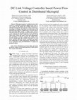
for more complicated cases. The studied system is shown in
Fig.1. Three V2G EVs are connected to a constant load which
has fixed active and reactive power consumption. The EV’s
DC battery packs are converted to AC with a DC/AC inverter.
According to [12], the interface impedance of EV zi (i=1,2,3)
is much larger than the line impedance zij ({(i,j)}=
{(1,2),(2,3),(3,4)}). Therefore, it is reasonable to neglect the
line impedance. Each V2G EV is represented as a voltage
source with an amplitude Vi, and phase angle Ʌi while the load
is modeled as a P+jQ constant PQ load. The amplitude and
phase angle of a V2G EV can be independently adjusted. In
this paper we assume the V2G EVs response fast and there are
no stator transients [13].
Figure 1. Studied V2G automatic load sharing system
Without any additional control, the load cannot be shared
proportionally among V2G EVs. In this study, at first the load
is -3-j1.6 pu, which is shared evenly among the three EVs.
However in reality, the load is not constant. A change in load
profile, for example the load is changed to -4-j2 pu, the
additional load will not be shared proportionally among three
EVs if these EVs maintain the same voltage profile. Given the
fact that each EV has its own maximum allowable V2G
power, it is entirely possible that due to the additional load one
of the EVs exceeds its maximum allowable V2G power and
causing battery damage and safety hazard. Therefore, it needs
a closed loop control algorithm to accommodate the load
change as well as generation change in the network.
B. V2G Automatic Load Sharing with Droop Controller
A droop controller for V2G automatic sharing is presented
for proportionally sharing the load within one micro-grid.
Several droop control algorithms for distributed generation are
studied in [13]-[15]. In this paper, a conventional droop
controller will be considered first and later a revised algorithm
better suit to V2G applications will be presented. The droop
controller used in this paper is presented as follows, for active
power control:
x
Gi
kpi ( Pmi Pi 0 )
(1)
kqi (Qmi Qi0 )
(2)
and reactive power control
'Vi
for i = 1,2,3, where δi denotes the phase angle of ith V2G EV,
ΔVi is the voltage difference between the instant voltage and
the initial voltage. Control parameters kpi and kqi are active
and reactive power droop coefficients for the ith EV,
respectively. Pi0 and Qi0 represent the reference active power
and reactive power. Pmi and Qmi are the measured active and
reactive power. The controller works like a droop, i.e., when
the measured active power is larger than the reference value; it
decreases its phase angle.
3
The sensors for measuring the active and reactive power
can be modelled as first order systems; the time-constant of
the system models the sensing delay:
Pmi ( s )
Pi ( s )
Zf
s Zf
(3)
x
G1
kp1 ( P1 P10 )
Zf
s Zf
(4)
where Pi(s) and Qi(s) represents the instant active and reactive
power of ith V2G EV and ωf is the time constant.
C. System Dynamicsof the Micro-grid
The power flow of each bus shown in Fig.1 can be
expressed as follows:
4
Pi
¦VV
i
j
(Gij cos G ij Bij sin G ij )
(5)
j
(Gij sin G ij Bij cos G ij )
(6)
j 1
4
Qi
¦VV
i
for i=1,2,3,4, where δij = δi-δj, and Gij and Bij can be
extracted from admittance matrix.
Following controller described in (1) and (2) and the
sensor dynamics in (3) and (4), the dynamics of the system is
described as follows:
x
x
' Pmi
x
' Qmi
kpi 'Pmi
(7)
Z f ('Pmi 'Pi )
(8)
Z f ('Qmi 'Qi )
(9)
i = 1,2,3, where
4
¦ 'PG
'Pi
'G j
(10)
j
'G j
(11)
j
0
i
j 1
4
¦ 'Q G
'Qi
0
i
j 1
and 'Pmi
Pmi Pi , 'Qmi
0
Qmi Q , 'PiG j and 'Q can be
0
i
0
iG j
0
obtained from (5) and (6) with partial differentials around
equilibrium points:
'PiG0 j
wPi
wG j
and 'Q 0
iG j
Pi 0
wQi
wG j
(13)
kp2 ( P2 P20 )
kp3 ( P3 P30 )
(14)
On the other hand, reactive power sharing is a much
complicated problem that requires further discussion. In the
following analysis, it is assumed that the micro-grid has a low
R/X ration and we assume there is no sensor delay in (4). Then
(6) can be rewrite as:
Qi
2
VV
i 4 Bi 4 cosG i 4 Vi Bii
(15)
for i=1,2,3, where Bi4=-Bii. Supposedly there is a change in
node 4. For simplicity without losing generality, the relative
angles δi4 stay exactly the same in active power steady state.
Then (15) can be reformulated as:
'Qi
(16)
kqi 'QV
i 4 Bi 4 cos G i 4 Vi 'V4 Bi 4cosG i 4 2kqi 'QV
i i Bi 4
Following (16), the reactive power is shared as follows:
j 1
Gi
x
G3
The system will falls into steady state when the changing
rates of δi are the same. In steady state, Pmi=Pi. Therefore, the
active power of the micro-grid is shared proportionally as
follows:
and
Qmi ( s )
Qi ( s )
x
G2
(12)
Qi 0
Expressions for (12) can be obtained from (5) and (6). The
dynamics of the system is linearized with (12) and can be
modeled with the above differential equations.
D. Active and Reactive Power Sharing with V2G
For active power, the system will reach a steady state,
when the following equations hold:
Vi kq j cos G i 4 (V4 B j 4 cos G j 4 2V j )
'Qi
'Q j
(17)
V j kqi cos G j 4 (V4 Bi 4 cos G i 4 2Vi )
for i,j =1,2,3. It is clearly shown that the reactive power
sharing is highly coupled. The proportion depends on a
number of parameters besides the reactive power sharing
coefficients.
E. V2G Automatic Load Sharing with Driver Preference
From the previous derivation and analysis, it is shown
though reactive power cannot be easily shared among V2G
EVs, active power is shared proportionally. Inspired by this
fact, this paper proposes a droop based active power sharing
with driver preference. The driver of each EV is able to
choose an upper limit that prevents active power shared
beyond the limit. It corresponds to different maximum V2G
power allowed for different EV models in practice. The
controller is described as follows:
°
®x
°¯G i
x
Gi
kpi ( Pmi Pi 0 )
Pi l
kpi (1 Pmi Pi )( Pmi Pi )
l
0
Pmmi
(18)
Pi d Pmi
l
where Pil is the maximum allowable active power sharing for
ith EV. The active load sharing works as conventional droop
controller when the measured power does not exceed the
maximum allowable power. However, when the measured
power exceeds the limit, the local droop based controller
dynamically adjusts its sharing coefficient based on the
feedback of how much power it exceeds the limit. The more
V2G power it exceeds its limit, the faster its active power
sharing coefficient increases, consequently the lower active
power the EV is sharing. It is noted that there is a possibility
when the supply of the grid cannot meets its demand, which
4
1
0
0
SYSTEM DESCRIPTION OF THE MICRO-GRID
Parameter
kp
kq
z1 (pu)
z2 (pu)
z3 (pu)
load (pu)
ωf (rad/s)
Value
[0.1 0.3 0.2]
[0.001 0.003 0.002]
0.01+j0.05
0.01+j0.10
0.005+j0.15
-3-j1.6
10
Fig.2 shows the automatic load sharing of the described
scenario. EV3 is not connected to the micro-grid at first with
both active and reactive power at 0pu. The load is shared by
EV1 and EV2. At t=1s, EV3 is connected to the original
network and additional generation is introduced to the microgrid. Active and reactive power of the load is shared by EV3.
Thus, P1 and P2 drops while P3 increase. It is noted that the
reference active power used in this simulation for EV3 is 2pu.
As shown in the figure, ΔP1=1.10pu, ΔP2=0.37pu,
ΔP3=0.56pu and kp1ΔP1= kp2ΔP2=kp3ΔP3 within acceptable
errors. The errors result from two major reasons: first, the
sensing delay of sensors; and second, the micro-grid studied in
this simulation is not a non-lossy network. Some shared active
power is compensated in the lossy network.
On the other hand, reactive power sharing is much more
complicated. It is observed that ΔQ1=0.13pu, ΔQ2=0.37pu,
ΔQ3=0.02pu. As shown in the Fig.2, reactive power sharing
has oscillations at each EV. This is expected, as shown in (16),
cosδi4 does not equal to a constant number before it reaches
steady state. As presented in (17), the reactive power sharing
is related to a number of factors besides the reactive sharing
coefficients, not to mention (17) is a simplification for nonlossy networks. To the best of authors’ knowledge, compared
1
2
3
Time (s)
4
Q2 (pu)
1
2
3
Time (s)
4
1
2
3
Time (s)
4
5
1
2
3
Time (s)
4
5
1
2
3
Time (s)
4
5
0.5
0
0
5
2
P3 (pu)
1
1
1.5
0.6
1
0
0
1.2
0.8
0
5
2
1
2
3
Time (s)
4
5
0.4
0.2
0
0
Figure 2. Automatic load sharing with V2G when an EV is connected to the
original micro-grid
Fig.3 presents the phase angle and voltage amplitude
change over time of the studied scenario. As indicated in the
figure starting from 1s, EV3 is connected to the network,
which introduces dynamic response to the system. The phase
angle differences δi-δj (i≠j, i,j=1,2,3) stay the same after the
changing rates δi (i=1,2,3) are synchronized. It is shown in
Fig.3 that after 3s, the three curves of phase angle are almost
parallel. It matches Fig.2 which shows a steady state of active
power sharing has reached after 3s. It also verifies the stability
analysis in (13) and (14).
Phase Angle Change Over Time
Voltage Magnitude Change Over Time
0.6
0.5
1.4
EV1
EV2
EV3
1.2
0.4
Phase Angle G (rad)
TABLE I.
Q1 (pu)
1.4
1
0
A. V2G Load Sharing with Additional EV Be Connected
In the first simulation, a fundamental V2G automatic load
sharing scenario is studied. Following the topology described
in Fig.1, originally EV1 and EV2 are connected to a constant
PQ load and reach a steady state. Then EV3 is connected to
the original network while the load stays constant. The target
of this simulation is to verify the controller as well as study its
dynamic behavior and stability. The system parameters of the
micro-grid are specified in Table I. The micro-grid is
modelled as a lossy network with a low R/X ration.
Reactive Power Sharing
Active Power Sharing
2
Q3 (pu)
Based on the analysis of the previous section, this section
simulates three practical scenarios of using V2G for automatic
load sharing, including a case when an EV is connected to the
network with constant load, a case when EVs are connected
but load changes and a case when load stays the same while an
EV is disconnected from the network. All other application
scenarios of V2G automatic load sharing in micro-grid level is
a combination of these three fundamental scenarios. Thus, it is
important to understand these three fundamental application
scenarios.
EV1
EV2
EV3
1
Voltage Magnitude V(pu)
SIMULATION RESULTS AND ANALYSIS
P1 (pu)
III.
to active power sharing, the problem of reactive power sharing
has not yet reached a universal and decent solution [12]-[16].
More efforts are needed to understand the reactive power flow
and resonance in power network.
P2 (pu)
may result in oscillation of the micro-grid. It will be discussed
in the following section.
0.3
0.2
0.1
0.8
0.6
0.4
0
0.2
-0.1
0
-0.2
0
1
2
3
Time (s)
4
5
0
1
2
3
Time (s)
4
5
Figure 3. Phase angle and voltage amplitude change over time of automatic
load sharing with V2G
B. V2G Load Sharing with Load Change and Driver
Preference
Apart from studying how an EV connection introduces
dynamics to the micro-grid level V2G load sharing, it is
5
Fig.4 presents the simulation results of load change with
driver preference in solid line and without driver preference
with dash line for 3 V2G EVs. At first, EV1, EV2 and EV3
are sharing active and reactive power at steady state. At t=1s,
the load changes from -3-j1.6pu to -5-j2pu. The additional
load will be shared among three V2G capable EVs. As shown
in the figure, after the load increases, EV1’s active power
sharing increases to 2pu which exceeds its maximum allowed
V2G active power. The controller in (18) detects the overflow,
and then dynamically decreases EV1’s active power sharing
according to the feedback of how much it exceeds the limit.
As shown in Fig.4, the active power sharing of EV1 is
constrained to 1.5pu versus if sharing 2.1pu if no driver
preference is implemented. The observed delay time before P1
decreases from 2pu is due to sensing delay. An overshoot is
observed at t=1.3s, which is desired: in practice, power
electronics can only sustain overcurrent for a short time. Thus,
an under-damped system with overshoot decreases its time
working in overcurrent operations.
C. V2G Load Sharing with EV Be Disconnected
In the end, it is necessary to study how EV’s disconnection
affects the power sharing of connected EVs while the load
stays constant. Combined with the previous two simulations, it
accounts for all fundamental V2G automatic load sharing
dynamics in a micro-grid.
During this simulation, the load is constant. As shown in
Fig.5, at first, three EVs are sharing active and reactive power
through V2G at steady state. At t=1s, EV3 is disconnected to
the micro-grid. It is observed that ΔP1=-0.79pu, ΔP2=-0.28pu,
which correspond to the active power sharing control kp1ΔP1=
kp2ΔP2. It is also observed ΔQ1=-0.17pu, ΔQ2=-0.31pu.
Similar to analysis in the previous section, the reactive power
is not shared according to reactive power sharing coefficient.
This simulation also shows that even for a simple case when
only load is shared between two V2G EVs, reactive power
sharing is hard to control. It needs more effort before
researchers can proportionally share reactive power as its
counterpart.
Active Power Sharing
Reactive Power Sharing
2
1.4
Q1 (pu)
As for preference, it corresponds to the upper limit of V2G
active power for each EV, i.e. Pil, mentioned in (18). In this
simulation, a case which one of the EVs has a lower allowable
V2G power is simulated: P1l=1.5pu, P2l=P3l=2.5pu. This is a
reasonable assumption because in practice, different EV
models allow different maximum V2G power.
preference controller can never reach a steady state. However,
this is something not expected as automatic load sharing only
make sense when generation meets the demand. Fig.4 also
presents the reactive power sharing under driver preference.
Though the driver preference controller is implemented for
active power sharing, it slightly affects relative power sharing.
This is expected, because (17) shows reactive power sharing is
related to δi4 which is affected by active power sharing.
P1 (pu)
essential to understand how power is shared when there are no
EV connections and disconnections dynamics, but rather a
load change in micro-grid. A simulation is run with EV1, EV2
and EV3 connected to the micro-grid supporting load through
V2G. Load change both in active and reactive then happens
and V2G EVs react to this change. This simulation shows how
driver preference affects automatic load sharing in micro-grid.
1.5
1
0
2
Time (s)
3
4
1
0
1
2
Time (s)
3
4
1
4
1
2
Time (s)
3
4
-2
-4
-6
0
1
2
Time (s)
3
4
1
1.5
1
0.5
0
3
4
2
Time (s)
3
1
2
Time (s)
3
4
1
2
Time (s)
3
4
0.8
0.6
0.4
0
4
0.4
1
2
Time (s)
3
4
1
0
0
1
1
2
Time (s)
3
1
2
Time (s)
3
1
2
Time (s)
3
4
0.2
0
-0.2
0
4
Figure 5. Automatic load sharing with V2G when an EV is disconnected to
the network
-1.5
-2
0
2
Time (s)
2
0.5
0
0
1
1
1.5
P3 (pu)
Q2 (pu)
3
Q3 (pu)
2
Time (s)
Q4 (pu)
P2 (pu)
P3 (pu)
P4 (pu)
2
1.5
1
0
1
1
0
4
1.5
0.5
0
2
1.5
1
0
3
Q2 (pu)
1
2
Time (s)
Q3 (pu)
2
P2 (pu)
3
1
0
1
Dash Line is without driver preference
Q1 (pu)
P1 (pu)
Solid line is with driver preference
1.2
4
Figure 4. Automatic load sharing with V2G when load changes
It is noted that there is a possibility when the three EVs’
maximum allowed V2G active power combined cannot meet
the demand of the load. In that case, the droop based driver
IV.
CONCLUSIONS
This paper presents a droop based automatic load sharing
with driver preference using V2G capable EVs in a microgrid. Unlike conventional centralized control methods, this
paper studies a scenario when communication is limited, and
V2G EVs have to adjust active and reactive power sharing
based on their own information. A micro-grid with connected
EVs is modeled as a lossy network with low R/X ration
without loss of generality. The power flow and load sharing
6
among EVs are carefully analyzed with reasonable
simplifications. A droop based controller taking into account
driver preference is proposed in this paper. It limits the V2G
active power sharing to the driver’s preset maximum value,
which models the maximum allowable V2G power in practice.
Stability of the controller is studied to understand the
robustness of the studied system. The analysis of the active
and reactive power sharing in a micro-grid level sheds light on
large scale V2G load sharing in distribution networks. Three
practical application scenarios of V2G load sharing are
simulated, which include a case when an EV is connected to
the micro-grid with constant load, a case when load changes
while EVs are connected and a case when an EV disconnects
to the micro-grid with constant load. All other application
scenarios of V2G automatic load sharing in micro-grid level is
a combination of these three fundamental scenarios.
Simulation results show that the proposed controller
constrained the active power sharing to the EV driver’s
preference. Simulation results also demonstrate the stability of
the system and proportional active power sharing among V2G
EVs. However, reactive power cannot be shared
proportionally as active power, due to the fact that it is highly
coupled. More efforts on understanding and decoupling the
reactive power sharing are needed in the future.
REFERENCES
[1]
[2]
[3]
[4]
Energy Information Agency, “2014 Annual Energy Outlook,” 2014
Yilmaz, M.; Krein, P.T., "Review of the Impact of Vehicle-to-Grid
Technologies on Distribution Systems and Utility Interfaces," Power
Electronics, IEEE Transactions on , vol.28, no.12, pp.5673-5689, Dec.
2013
Ching-Yen Chung; Youn, E.; Chynoweth, J.; Qiu, C.; Chi-Cheng Chu;
Gadh, R., "Safety design for smart Electric Vehicle charging with
current and multiplexing control," Smart Grid Communications
(SmartGridComm), 2013 IEEE International Conference on.,
pp.540,545, 21-24 Oct. 2013
S. Mal, A. Chattopadhyay, A. Yang, R. Gadh;, “Electric vehicle smart
charging and vehicle-to-grid operation, International Journal of Parallel,
Emergent and Distributed Systems,” vol. 27, no. 3. pp. 249-265 March
2012.
[5]
[6]
[7]
[8]
[9]
[10]
[11]
[12]
[13]
[14]
[15]
[16]
W. Kempton and J. Tomic, “Vehicle-to-grid power fundamentals:
Calculating capacity and net revenue,” Journal of Power Sources, vol.
144,no.1,pp.268–279,2005.
Zhenpo Wang; Shuo Wang, "Grid Power Peak Shaving and Valley
Filling Using Vehicle-to-Grid Systems," Power Delivery, IEEE
Transactions on , vol.28, no.3, pp.1822-1829, July 2013
C. Wu, H. Mohsenian-Rad, and J. Huang, “Vehicle-to-aggregator
interaction game,” IEEE Trans. Smart Grid, vol. 3, no. 1, pp. 434–442,
Mar.2012.
Sekyung Han; Soohee Han; Sezaki, K., "Estimation of Achievable
Power Capacity From Plug-in Electric Vehicles for V2G Frequency
Regulation: Case Studies for Market Participation," Smart Grid, IEEE
Transactions on , vol.2, no.4, pp.632-641, Dec. 2011
Lam, A.Y.S.; Ka-Cheong Leung; Li, V.O.K., "Capacity management of
vehicle-to-grid system for power regulation services," Smart Grid
Communications (SmartGridComm), 2012 IEEE Third International
Conference on , vol., no., pp.442,447, 5-8 Nov. 2012
Yang Gao; Yan Chen; Chih-Yu Wang; Liu, K.J.R., "A contract-based
approach for ancillary services in V2G networks: Optimality and
learning," INFOCOM, 2013 Proceedings IEEE , vol., no., pp.11511159, 14-19 April 2013
Yang, Zhenyu; Shucheng Yu; Wenjing Lou; Cong Liu, " P^2 : PrivacyPreserving Communication and Precise Reward Architecture for V2G
Networks in Smart Grid," Smart Grid, IEEE Transactions on, vol.2,
no.4, pp.697-706, Dec. 2011
Sao, C.K.; Lehn, P.W., "Autonomous load sharing of voltage source
converters," Power Delivery, IEEE Transactions on , vol.20, no.2,
pp.1009-1016, April 2005
Pota, H.R., "Droop control for islanded microgrids," Power and Energy
Society General Meeting (PES), 2013 IEEE , vol., no., pp.1-4, 21-25
July 2013
Coelho, E.A.A.; Cortizo, P.C.; Garcia, P.F.D., "Small-signal stability
for parallel-connected inverters in stand-alone AC supply systems,"
Industry Applications, IEEE Transactions on , vol.38, no.2, pp.533-542,
Mar/Apr 2002
Simpson-Porco, J.W.; Dorfler, F.; Bullo, F., "Voltage stabilization in
microgrids via quadratic droop control," Decision and Control (CDC),
2013 IEEE 52nd Annual Conference on , vol., no., pp.7582-7589, 1013 Dec. 2013
Xinyao Li; Dysko, A.; Burt, G., "Enhanced mode adaptive
decentralized controller for inverters supplying a multi-bus microgrid,"
Innovative Smart Grid Technologies Europe (ISGT EUROPE), 2013
4th IEEE/PES , vol., no., pp.1-5, 6-9 Oct. 2013
Keep reading this paper — and 50 million others — with a free Academia account
Used by leading Academics

Jean-Yves Fortin
Centre National de la Recherche Scientifique / French National Centre for Scientific Research

Kiran Dasari
University of Illinois at Urbana-Champaign

Dimitris Askounis
National Technical University of Athens
Mojtaba Dehmollaian
University of Tehran