Proceedings of the 2005 IEEE
International Conference on Robotics and Automation
Barcelona, Spain, April 2005
Biologically Inspired Adhesion
based Surface Climbing Robots
Carlo Menon
Metin Sitti
CISAS “G. Colombo”
University of Padova, 35131 Padova, Italy
menoncarlo@stargatenet.it
Department of Mechanical Engineering
Carnegie Mellon University, Pittsburgh, PA 15213, USA
sitti@cmu.edu
Abstract— Climbing robots can perform many tasks
inaccessible to other robots or humans such as inspection,
repair, cleaning, surveillance, and exploration. This paper
presents and discusses the design, fabrication, and evaluation
of two novel bio-inspired climbing robots. Both are inspired
by the locomotion of Geckos, a highly skilled natural climber.
They are developed for terrestrial and extra-terrestrial
environments, and their kinematics is inspired by the Geckos’
gait. The first relatively large robot actuated by conventional
motors is designed to operate at both in Earth and space
scenarios. The second robot, whose motion is controlled using
shape memory alloy actuators and size can be miniaturized to
few centimeters scale, is designed for terrestrial applications.
Preliminary prototypes of these robots are developed,
demonstrated, and evaluated by steep and flat acrylic surface
climbing tests. Current robots can successfully climb up to
65° slopes at 2 cm/sec speeds.
presented. The first robot, called the Rigid Gecko Robot
(RGR), has been designed for operating in space
environments. Reliability and robustness are the most
important requirements for the RGR. The second robot,
called the Compliant Gecko Robot (CGR), has been
designed using unconventional technologies which will
allow robot miniaturization. The CGR prototype has a
composite structure and its Gecko mimicking locomotion
relies on shape memory alloy wire actuators.
Index Terms— Biomimetic robots, climbing robots,
micro/nanorobots, space robots
II.A Adhesive Pad and Foot Design
Much work has been devoted to the development of
attachment mechanisms for climbing robots. Suction based
attachment [7] requires the robot to carry an onboard pump
to create a vacuum inside cups which are pressed against
the wall or ceiling. However, this mechanism is slow,
consumes high power, does not work in space
environment, and any gap in the seal can cause the robot to
fall. Another attachment mechanism relays on magnetic
adhesion [8]. Magnetic attachment is possible only in very
specific environments, e.g., nuclear facilities, where the
surface is ferromagnetic. Thus, this solution is unsuitable
for many applications.
Another strategy is to study passive attachment
mechanisms, like those used by climbing animals. The
Tokay Gecko, for example, can weigh up to 300 grams and
reach lengths of 35cm, yet is still able to run inverted and
cling to smooth and rough walls. Unique adhesive pads
allow Geckos’ incredible climbing performance without
contaminating the surrounding environment. Synthetic dry
fibrillar adhesive has been developed to mimic the Gecko
adhesive pad structure with promising initial results. Using
micro-molding techniques, 4µm diameter micro-fibers
have been obtained [9]. This fibrillar adhesive, however, is
still under development and does not yet achieve as high
performances as other soft and dry adhesives. Synthetic
gecko adhesive was tested and compared to soft adhesives
such as Silly Putty® and flat polydimethyl siloxane
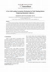
(PDMS). Fig. 1 shows results obtained using a customized
tensile adhesion measurement test-bed. Adhesives had a
I
INTRODUCTION
The locomotion, sensing, navigation, and adaptation
capabilities in animals have long inspired researchers in
robotic system design. The purpose of this study is to
determine the potential of climbing robots for both
terrestrial and extra-terrestrial applications. The
development of climbing robots is mainly driven by
automating tasks which are currently accomplished
manually at a risk to the human workers. Robots could
reduce the risk to humans in many different applications.
Moreover, the ability to climb surfaces and walk are also
crucial for inspection and maintenance of space shuttles,
satellites, nuclear plants [1], search-and-rescue for
homeland security [2], cleaning and painting [3],
exploration on planets or hazardous regions, and
micro/nano-scale manufacturing applications [4]. These
autonomous robots encounter mostly unstructured
environments, only accessible by legged locomotion and,
in particular, climbing. Many legged animals, e.g.,
cockroaches, beetles, ants, and crickets [5], have walking
abilities which have been studied to develop a new
generation of mobile robots. Geckos’ climbing ability has
attracted scientists’ attention since they can adhere to most
surfaces robustly and climb with very high
maneuverability and agility [6].
This paper proposes Gecko inspired climbing robots for
applications in unstructured environments. Design,
fabrication and test phases of two robot prototypes are
II
ROBOT DESIGN
Geckos differ from other climbing animals especially
for their adhesion system and locomotion. In this section,
the strategy for developing a Gecko inspired attachment
pad, feet, and robot prototype is presented and discussed.
size of 95mm2. They were loaded against a glass surface
with a preload of 75mN, an approach velocity of
0.08mm/s, and a retracting velocity of 0.4mm/s. The
contact time was 1s.
Silly Putty
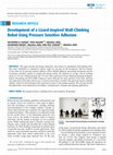
Fig. 2 Pictures of Gecko Robot prototypes.
Flat PDMS
Plastic
behavior
Dry adhesive
Fig. 1 Adhesion behavior of various soft and fibrillar adhesives under 75
mN preload and 1s contact time.
Fig. 3 Output for the multi-body software: torque for the motor positioned
on the middle of the gecko robot back
Fig. 1 also shows that Silly Putty® exerts the highest
normal adhesive force and it was therefore chosen for our
robotic application.
II.B Rigid Gecko Robot Design
In this section, the kinematics and dynamics of the Rigid
Gecko Robot are discussed. Fig. 2 shows the twodimensional kinematic model of the RGR prototype. The
robot has ten degrees of freedom (DOF), as shown in the
left side of Fig. 2. The first four-DOFs ( numbers 1, 2, 3, 4
in Fig. 2) are use for lifting robotic legs by means of four
motors; one-DOF (number 5), in the middle of the robot’s
back, is necessary for robot locomotion and it is controlled
using another motor. The other five-DOFs are passive
revolute joints. The right side of Fig. 2 shows that the
planar kinematics of the robot can be represented by a
four-bar-linkage.
The dynamics of the RGR in vertical climbing mode
were studied using multi-body software (VisualNastran
Desktop 4D), and a three-dimensional robot model with
realistic specifications. The robot model was 10cm long,
10cm wide, and it weighed 80g. The rotation of the motor
controlling the robot’s back displacements (number 5 in
Fig. 2) was the input for the dynamic simulation.
Fig. 3 shows the torque output for the same motor. This
torque was necessary for counterbalancing the weight and
dynamic forces caused by the robot motion.
Fig. 4 shows both the robot model and the adhesive
forces required by the most stressed robot foot. The shear
forces, Fy and Fz, are bigger than the normal force, Fx. The
total force is 1.5 N.
Instability
Fig. 4 Rigid Gecko Robot simulated dynamic analysis: left: RGR model;
right: robot foot forces during vertical climbing phase
The results of the multi-body software analysis were
used to select the adhesive pad size. Since the adhesive
material, Silly Putty®, has a plastic behavior, the Bowden
Tabor equation holds:
Ft = τ ⋅ Ac
(1)
The necessary contact area was determined to be 6cm2.
Dynamic simulation results show numerical instabilities
after 0.22s and 0.25s (right side of Fig. 4). The robot
position which causes these instabilities is shown in the
left side of Fig. 5. If the Back Revolute Joint (BRJ) is
controlled by motor torque, three passive revolute joints
are affected by dynamic loads: the Middle Revolute Joint
(MRJ), the Hind Revolute Joint (HRJ) and the Fore
Revolute Joint (FRJ), which represents the feet in contact
with the vertical surface. The robotic model can thus be
simplified in a three-bar-linkage as shown in the right side
of Fig. 5. For small displacements, this configuration has
an additional redundant DOF which makes the robot
motion unstable [10]. In the real robot prototype,
mechanical joint clearances amplify instability effects thus
compromising the robot climbing performance.
Robot kinematic analysis shows that the instable
configuration is avoided by:
1. Increasing the length of fore legs.
2. Decreasing the length of hind legs.
3. Changing the position of the motor.
4. Decreasing the angle range of the BRJ rotation.
For the RGR prototype, the fourth solution was chosen
since a symmetrical configuration of the robot was
preferred.
Fig. 5 On the left, the RGR is represented in its unstable configuration; on
the right, a schematic representation of the gecko robot showing the
model to be studied for understanding its unstable configuration.
(FLJ=Fore Left Joint; HRJ=Hind Right Joint; FRJ=Fore Right Joint;
HLJ=Hind Right Joint; BRJ=Back Right Joint)
II.C Compliant Gecko Robot Design
A new compliant system has been developed for the
CGR in order to facilitate future design of miniaturized
climbing robots. This robot has a composite material frame
and shape memory alloy (SMA) wires provide motion that
mimics gecko muscles. The compliant robotic back (Fig.
6) is flexible, and SMA wires are attached to both sides.
The flexible robot back is able to recover the initial length
of the SMA wires during their cooling phase. This system
is used to locomote the CGR.
The geometry of the robot was optimized both to have
long robot steps and amplify SMA wires’ force. With
regard to robot step optimization, analytical kinematic
equations were derived taking into account flexible robotic
back characteristics.
considered of the same lengths (m=b).
Fig. 7 shows that if the robot length (parameter a)
increases, then the robot step ∆L decreases. Additionally,
the condition a+m=constant means that the robot step
increases when the length of the robot legs increases. The
ideal robot must therefore have long legs and a short back.
Fig. 7 The variation of L, ∆L, decreases when the variable (a) increases.
The variables (a) and (m) are constrained by equation a+m=constant. The
SMA wires can be contracted up to 4% of their length.
The second analysis focused on CGR back deflection
during the contraction of the SMA wires. Since the CGR
back is fixed differently to the fore and hind robotic legs
(Fig. 2), the compliant back was modeled as a cantilever
with an external normal force, R, and a moment, M,
applied to its end (Fig. 8). Both R and M are functions of
the cantilever deflection and their values were therefore
computed in an iterative procedure during CGR back
deflection. The effect of the distance spacer, s, on the
distance, d, and force, F, (Fig. 8) was studied using large
deflection theory [11].
Fig. 8 Model for the SMA force analysis. The CGR can be reduced to
the study of a cantilever contracted by a SMA wire. The distance spacer
(s) introduces a variable moment M.
Fig. 6
Compliant Gecko Robot model
Analysis was necessary to obtain ∆L, the robot step
length, as a function of all the other parameters, a, b, c, and
m of Fig. 6. In order to compare the effects of a and m and
obtain the corresponding physical solution, the condition
a+m=constant was used. In addition, the maximum
contraction of the wires was limited to the 4% of their
length because of the inherent SMA wire characteristics.
For the sake of simplicity, fore and hind legs were
The flowchart in Fig. 9 shows the used iterative
procedure. Parameters r0 and F0, the approximated
cantilever curvature and the estimated SMA constant force,
respectively, represent the initial software inputs. For the
sake of simplicity, Fig. 9 does not show all software
subsystems, e.g. subsystems for computing elliptic
integrals, which are involved in the cantilever large
deflection computation.
Fig. 10 shows results obtained using realistic data of the
CGR prototype back: Young’s elastic modulus=226GPa;
back length=10cm; back width=2.4cm. Fig. 10 is very
important in considering control strategies. In fact, the
developed cantilever deflection model can be used in a
feed-forward control loop.
Fig. 11 Control Strategy for one-full robot step: time evolution of the
rotations of each motorized joint.
Fig. 9 Flowchart of the software developed for the iterative computation
of CGR back deflection. Large deflection theory was used.
Fig. 10 Forces that the SMA wires exert for bending the CGR back.
Different curves correspond to different values of the distance spacer s.
For the CGR locomotion design, weight and dynamic
forces were neglected as the robot prototype was designed
to be very light and to climb slowly.
III EXPERIMENTAL SYSTEMS
In this section, actual RGR and CGR prototypes are
presented. Robot specifications and characteristics are also
discussed.
III.A Rigid Gecko Robot Prototype
The chassis of the RGR, which was designed to operate
in macroscale and for future space applications, was built
using aluminum alloy. The robotic frame was obtained
through folding techniques starting from aluminum sheets.
RGR was equipped with five electrical solenoid motors,
four for lifting the robotic legs, and one for the robot
locomotion. The maximum torque of each motor, which
was amplified by 81:1 gearboxes, was 25Nmm obtained
using 5V. The RGR received off-board power and was
controlled by a PIC 16F877 micro-controller integrated in
a built-customized electronic board. Fig. 11 shows the
control strategy used for one-full robot step. All five
motors were controlled in a particular sequence in order to
detach one foot per time minimizing the risk of robot
falling.
III.B Compliant Gecko Robot Prototype
The fabrication of the CGR, shown in Fig. 12, was very
challenging due to the use of SMA wires and composite
material chassis. The CGR back was equipped with 50µm
diameter SMA wires with a transition temperature of about
90°C (Flexinol® high temperature SMA wires). Several
thin wires were used instead of few thick wires in order to
increase the natural convection effect during SMA wires’
cooling phase. For the heating phase, an external power
system was used. The maximum contraction of the wires
was 0.6cm, 6% of their length (10cm), and was obtained
using 5V. The thermal cycle rate was 1cyc/s.
The CGR chassis was built with a composite structure
made of the following three layers:
1. Unidirectional prepreg glass fiber (S2Glass) having
30µm thickness.
2. Prepreg carbon fiber (M60J) weaves having 80µm
thickness.
3. Unidirectional glass fiber (S2Glass) having 3cm
thickness.
The use of glass fiber had two different purposes: 1)
Reinforcing the compliant body structure; 2) Electrically
isolating the CGR frame when in contact with SMA wires.
A thin layer of epoxy, obtained by the use of a spinner
machine, was also spread over the composite robot back in
order to increase the electrical isolation.
Composite material theory was used to compute the
mechanical properties of the CGR back laminate (Table 1).
Table 1
E1 (GPa)
E2 (GPa)
G12 (GPa)
ν12
226
205
7
0.3
The final CGR back was 2.4cm wide and 12cm long.
Six SMA wires, which were fixed on each side of the
robot, were able to bend the CGR back and provide robot
locomotion. Three composite material failure theories
(Tsai-Hill, Hoffman, and Tsai-Wu [12]) were used to
structurally verify the CGR compliant back when bent by
SMA wires.
Fig. 12 Photo of the Compliant Gecko Robot prototype
The construction of the middle revolute joint (Fig. 5 and
Fig. 6) was carried out using a compliant joint of PDMS.
Robot legs were controlled using 100µm diameter SMA
wires which had 0.7cyc/s thermal cycle rate. The leg
configurations made it possible to use long SMA wires
(14cm) able to lift the robot feet up to 0.5cm. The CGR
received off-board power.
The RGR and CGR have comparable sizes but the
technological solutions which were developed for the CGR
allow a feasible robotic miniaturization by simply scaling
down the already built prototype.
IV TEST RESULTS
The RGR had a robust behavior while walking in a
horizontal plane showing a gait similar to Gecko. Fig. 13
shows three RGR snap-shots during the climbing phase.
and turned on only for attaching and detaching phases.
This strategy would allow the robot to consume 130mW.
Static and dynamic tests were also carried out on the
Compliant Gecko Robot, in order to characterize the
compliant back behavior. The measurement equipment
included a laser scan micrometer able to measure
displacements of the compliant back during SMA wires’
contraction. The resolution of the micrometer was of 2µm.
The length of the compliant back was of 12cm.
Fig. 14 shows the SMA wire voltage as a function of
CGR back displacements d (see also Fig. 8). Even though
Fig. 14 and Fig. 10 have different y-axes, they can be
compared since the voltage applied to SMA wires is
proportional to the force that the wires exert. In a steady air
environment, the SMA wire force is proportional to the
SMA wire temperature [13]. In addition, the relationship
between temperature and voltage can be expressed as
follows:
& V #
& V #
T = a1 ⋅ $$
!! + a 2 ⋅ $$
!!
% ρ⋅D"
% ρ⋅D"
2
(2)
where ρ is the resistance of the SMA wire, D is the SMA
wire diameter, V is the voltage applied to the SMA wire,
and a1 and a2 are empirical constants. Since a1, whose
value is about 0.7, is two orders of magnitude higher than
a2 (0.006), the second term of the above equation can be
neglected. Since SMA voltage is proportional to SMA
temperature, which is also proportional to SMA force, by
the transitive property, SMA voltage and SMA force are
proportional.
Experimental results of Fig. 14 are consistent with
theoretical results of Fig. 10 suggesting the use of the
model developed in section II.C, in a feed-forward control
loop in order to predict compliant back behavior.
Fig. 13 Snap-shots of the RGR while it climbs a surface inclined at 65°.
RGR characteristics are shown in Table 2.
Table 2
RGR performance results and characteristics
Rigid Gecko Robot
Weight (g)
Length (cm)
Width (cm)
Speed (cm/s)
Power Consumption (mW)
Slope Angle (degrees)
80
10
10
2
360
65
The maximum speed, 2cm/s, was mainly limited by
software parameters. A speed of 6cm/s is expected by
modifying the control law. The RGR was able to climb, in
any direction, an acrylic surface inclined at 65° with
respect to a horizontal plane. The performance of the
robot, which was potentially able to climb a vertical
surface, was mainly limited by the absence of encoders for
the feedback control of the leg positions. The use of
encoders can also reduce the RGR power consumption. In
fact, motors could be turned off when the legs are lifted
Fig. 14 Behavior of the CGR back during SMA wires’ contraction
The dynamic behavior of the compliant back was
characterized recording its displacement during SMA wire
contractions. Fig. 15 shows the temporal evolution of the
compliant back for both heating and cooling SMA phases
using three different voltages. Analyzing Fig. 15:
1. If the SMA wire length is changed without
intermissions, the cycling time is about 1 cyc/s.
2. Increasing the voltage from 4V to 6V, the maximum
CGR back displacement increases only of 0.5mm.
3. The cooling phase had a dominant effect on the whole
cycle time.
4. Increasing the voltage results in a jitter effect.
These considerations suggest the use of the minimum
voltage necessary for obtaining a desired displacement.
This is also the best condition for CGR power
consumption.
An instability effect is observed when 5V are used: the
graph in the middle of Fig. 15 shows that the first pick of
the curve is lower than the second one. This instability is
caused by the dynamic behavior of the SMA wires and the
elastic compliant back. The contraction of the SMA wires
bends and accelerates the CGR compliant back. The inertia
force of the back temporarily overcomes the back elastic
force. The compliant back starts to vibrate. The first
oscillation is interrupted by the SMA wire action (point A
in Fig. 15) which results in another contraction of the GCR
compliant back. This instability can be reduced increasing
the dumping and decreasing the mass of the compliant
back. One possible solution is to replace the carbon fibers
with aramidic fibers and lighten the laminate by reducing
the epoxy in the composite matrix.
The performance and characteristics of the CGR are
shown in Table 3. This robot, which was able to climb a
65° slanted surface, was manually controlled and thus the
velocity (∼0.3cm/s) and power consumption (∼1W) were
functions of the operator ability.
Table 3
CGR performance and characteristics
Compliant Gecko Robot
Weight (g)
10
Length (cm)
10
Width (cm)
10
Slope Angle (degrees)
65
V
CONCLUSIONS
The significance of realizing agile robots able to avoid
obstacles and climb any kind of surfaces has driven the
research to focus on the ability of animals able to climb
vertical walls. The two developed prototypes which are
presented in this paper, demonstrate the feasibility and
capability of novel robot designs inspired by Gecko
locomotion. Experimental results show that the two robots
are potentially able to climb vertical surfaces although
adhesive characteristics and uncontrolled leg positions
limit their performance. The maximum slope of the
climbed acrylic surface was 65°. The highest recorded
speed was 2 cm/s, but 6 cm/s is the velocity expected by
improving the control law of the guiding software. Future
work includes miniaturization and implementation of new
synthetic adhesives for space environment operations.
Fig. 15 Dynamic behavior of SMA wires using 5V
ACKNOWLEDGMENT
The authors thank to Burak Aksak for electronic board
design, Eugene Cheung for experimental adhesive
measurements, Ozgur Unver for rigid gecko robot
fabrication, Murat Asci for robot foot fabrication, Sandy
Hsieh for compliant robot tests, and especially Thomas
Quentin Berna for compliant gecko robot fabrication.
REFERENCES
[1] L. Briones, P. Bustamante, and M. Serna, “ROBICEN: A wallclimbing pneumatic robot for inspection in nuclear power plants,”
Robotics and Computer-Integrated Manufacturing, vol. 11, pp. 287-9,
1994.
[2] K. Yesin, B. Nelson, N. Papanikolopoulos, R. Voyles, and D.
Krantz, "Active Video System for a Miniature Reconnaissance Robot,"
Proc. of the IEEE Int. Conf. on Robotics and Automation, pp. 3920-25,
2000.
[3] S. Hirose, A. Nagakubo, and R. Toyama, “Machine that can walk
and climb on floors, walls and ceilings,” Proc. of the Int. Conf. on
Advanced Robotics, pp. 753-8, 1991.
[4] S. Martel, P. Madden, L. Sosnowski, I. Hunter, and S. Lafontaine,
"NanoWalker: a fully autonomous highly integrated miniature robot for
nano-scale measurements", Proc. of the SPIE Int. Symp. on Envirosense,
Microsystems Metrology and Inspection, p. 3825, Germany, 1999.
[5] Y. Jiao, S. Gorb, and M. Scherge, “Adhesion measured on the
attachment pads of tettigonia viridissima (ortheptera, insecta),” Journal
of Experimental Biology, vol. 203, pp. 1887-1895, 2000.
[6] K. Autumn, Y. Liang, T. Hsieh, W, Zesch, W.P. Chan, T. Kenny, R.
Fearing, and R.J. Full, “Adhesive force of a single gecko foot hair,”
Nature, 405, pp. 681-5, 08 June 2000.
[7] R.T. Pack, J.L. Christopher, K. Kawamura, “A Rubbertuator-Based
Structure-Climbing Inspection Robot,” Proceedings of the IEEE
Conference on Robotics and Automation, pp. 1869-1874, 1997.
[8] H.R. Choi, S.M. Ryew, T.H. Kang, J.H. Lee, and H.M. Kim, “A
wall climbing robot with closed link mechanism”, Proc. of the Intelligent
Robotic Systems Conference, pp. 2006-2011, vol. 3, 2000.
[9] C. Menon, M. Murphy, and M. Sitti, "Gecko Inspired Surface
Climbing Robots" Proc. of the IEEE International Conference on
Robotics and Biomimetics (ROBIO), Shenyang, China, Aug 2004.
[10] C.R. Hibbeler, “Structural analysis,” Prentice Hall, 2001.
[11] Larry L. Howell, “Compliant Mechanisms”, Wiley-Interscience,
2001.
[12] I.M. Daniel and O. Ishai, “Engineering Mechanics of Composite
Materials,” New York, Oxford, Oxford University Press, 1994.
Academia.edu no longer supports Internet Explorer.
To browse Academia.edu and the wider internet faster and more securely, please take a few seconds to upgrade your browser.
A Time Delay Compensation Method Improving Registration for Augmented Reality
Proceedings of the 2005 IEEE International Conference on Robotics and Automation, 2005
By Malik Mallem
...Read more
Related Papers
AIAA 5th Aviation, Technology, Integration, and Operations Conference, 2005
Download
IEEE Access
Download
Proc. of the Bioinspiration and Robotics: Walking and Climbing Robots, 2007
Download
IEEE/ASME Transactions on Mechatronics, 2007
Download

Applied Sciences, 2021
Download

Download
Journal of Bionic Engineering, 2013
Download

Medicina nei Secoli, 2024
Download

Al-'Usur al-Wusta: The Journal of Middle East Medievalists, 2023
Download

