Materials and Manufacturing Processes
ISSN: 1042-6914 (Print) 1532-2475 (Online) Journal homepage: http://www.tandfonline.com/loi/lmmp20
Investigation of Process Parameters Influence in
AWJ Cutting of D2 Steel
Yuvaraj Natarajan & Pradeep Kumar Murugasen
To cite this article: Yuvaraj Natarajan & Pradeep Kumar Murugasen (2016): Investigation
of Process Parameters Influence in AWJ Cutting of D2 Steel, Materials and Manufacturing
Processes, DOI: 10.1080/10426914.2016.1176183
To link to this article: http://dx.doi.org/10.1080/10426914.2016.1176183
Accepted author version posted online: 29
Apr 2016.
Published online: 29 Apr 2016.
Submit your article to this journal
Article views: 64
View related articles
View Crossmark data
Full Terms & Conditions of access and use can be found at
http://www.tandfonline.com/action/journalInformation?journalCode=lmmp20
Download by: [Anna University]
Date: 23 June 2016, At: 01:31
Investigation of Process Parameters Influence in AWJ Cutting of D2 Steel
Yuvaraj Natarajan1, Pradeep Kumar Murugasen1
1
Department of Mechanical Engineering, Anna University, Ch-25, India
Corresponding author Yuvaraj Natarajan E-mail: yuvaceg09@gmail.com,
yuvabitt09@gmail.com
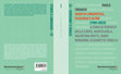
Abstract
In the present experimental study, abrasive water jet (AWJ) cutting tests were conducted
Downloaded by [Anna University] at 01:31 23 June 2016
on D2 steel by different jet impingement angles and abrasive mesh sizes. The
experimental data was statistically analyzed using the simos-grey relational method and
ANOVA test. In addition, the outcome of influencing cutting parameters, namely jet
pressure, jet impingement angle and abrasive mesh size on the different response
parameters, namely, the jet penetration, material removal rate, taper ratio, roughness and
topography, were studied. Micro hardness test and surface morphology analyis were
employed to examine the D2 cut surfaces at different AWJ cutting conditions. The
chemical element study was performed to determine the abrasive particle contamination
in the AWJ kerf wall cut surfaces. The ANOVA test result indicated the jet pressure and
jet impingement angle as the influencing process parameters affecting the various
performance characteristics of AWJ cutting. The overall AWJ cutting performance of the
D2 steel has been improved through proper identification of the optimal process
parameter settings, namely jet pressure 225 MPa, abrasive mesh size #100 and jet
impingement angle 70o by the simos-grey relational analysis.
1
KEYWORDS: Cutting; AWJ; Steel; Abrasive; Angle; Size; Simos-Grey; Topography;
Microhardness; Morphology
INTRODUCTION
AISI D2 steel is widely used in tool making applications in die and mould making
industries for production of a large number of automobile components. It is highly
enriched with chromium and carbon content which increase corrosion resistance,
Downloaded by [Anna University] at 01:31 23 June 2016
abrasion and wear resistance [1]. Past researchers have reported that machining of
die/tool steel is a difficult task when conventional processes are used. In the earlier stage,
it is machined in the annealed state. It is followed later by heat treatment, EDM, grinding
process, etc [2]. When it is in the hardened state, the cutting tool undergoes rapid tool
wear, poor chip formation, tool breakage, high cutting temperature, machined surface
alteration, also taking more time which leads to a decrease in the productivity [3]. Due to
this, unconventional machining processes were used to machine the D2 steels. It is
machined by wire electrical discharge machining, and electrical discharge machining
produced more heat generation at the machined zone and this leads to produce severe
defects such as crack formation, phase transformation, etc [4]. Different techniques have
been proposed by past researchers for reduction of the heat affected zone in the
machining of die steels and tool steels, but it cannot be avoided due to the heat generation
during milling, high speed milling and drilling, EDM, WEDM and Laser machining
operation which are intrinsic characteristics of the thermal based energy process. This
results in a poorly machined product. Further, the bulk content of the undissolved
chromium carbide particles present in the D2 steel promotes different wear of the tools
2
and imparts the material as extremely complex to machine [5]. In this case, abrasive
water jet (AWJ) machining is quite suitable for hardened die and tool steels, due to the
generation of the reduced heat, and absence of tool wear problem, as water acts as a
cutting tool, with no alterations in the properties of the work material [6].
In AWJ cutting, the material is removed through the erosion process in which the
abrasive particles are entrained with the high velocity of water jet, and their impingement
Downloaded by [Anna University] at 01:31 23 June 2016
towards the work material. Ductile erosion is caused by two principal wear modes such
as cutting wear and deformation wear [7]. Almost all kinds of materials are machined by
AWJ cutting. Only very few researchers have attempted the limited experimental
investigation on die steel by abrasive water jet cutting [8,9].
Some areas of the literature related to the machining of various die and tool steels by
AWJ cutting and other machining processes are presented below. Deepak et al. [8] have
studied the AWJ cutting of D2 steel by varying the effect of the traverse rate and standoff distance. They considered limited output parameters, namely, kerf width and surface
roughness. The results showed that multi-pass operation is only favoured for machining
thick D2 steels. Hlavac et al. [9] have investigated the kerf taper cut in different grade of
steels with a thickness of 30 mm by AWJ cutting. They report that ductility of the steel
causing variation in taper cut. Ankush and Lalwani [10] report the identification of
process parameters in AWJ cutting of H13 die steel. They report traverse rate as the
substantial factor for the machining of H13 die steel by an AWJ. Asif et al. [11] have
identified the AWJ cutting parameters for 20 mm and 40 mm thickness of 4340 tool steel.
3
The optimized result indicates the thickness of the work material and traverse speed as
better influencing cutting parameters for hardened material. Koshy et al. [5] have
investigated the machining of D2 steel by high speed end milling. The results indicated
that high tool wear was found due to the combined effect of the bulk hardness and
adverse chemical composition structure. Ersan et al. [12] report the milling of 4140 steel
by a ceramic insert. They found a high intensity of brittleness of the ceramic type insert
leading to increase the tool wears; as a result the surface roughness was increased. Helen
Downloaded by [Anna University] at 01:31 23 June 2016
et al. [13] have studied the high speed drilling and tapping of D2 steel, and their results
found the tool life getting extended upto six and nine holes in drilling and tapping
respectively. Bhattacharya et al. [14] report that electrical discharge machining (EDM) of
die steel requires high current to initiate the material removal process than those of EN31 and H11 steels. Kiayk and Cakir [15] have examined the EDM parameters on P20 tool
steel results showing better surface quality and lower metal removal rate, causing the use
of high cost in the machining. Even though a good surface finish was obtained in the die
steel by laser machining, and requiring some additional approaches for a higher material
rate with high surface finish as was investigated by Kaldos et al [16]. Choi et al. [17]
observed more cracks and poor surface finish on the machined die steel by the wire EDM
process, and it happened due to the effect of the heat affected zone.
According to the existing literature, the machining of D2 steel by other machining
processes causes poor machinability in terms of lower productivity, huge cost through the
involvement of high tool wear, lower rate of material removal, and poor surface quality.
A few researchers have done the machining of D2 steel by AWJ machining [8,9].
4
However, many of the performance evaluation parameters, and multi response
optimization studies were not revealed by the researchers [18]. Apart from that,
researchers made efforts to enhance the cutting performance of AWJ through different
techniques, such as the recycling of abrasives [19], change of jet impingement angle on
composites [20], alumina ceramics [21] and AA6061-T6 alloy [22], abrasive mesh size
and shape [23], nozzle oscillation technique [24], etc. These are the techniques developed
without any additional cost and can be used more effectively in the AWJ cutting of any
Downloaded by [Anna University] at 01:31 23 June 2016
work materials.
The process parameters namely jet traverse speed, jet pressure, stand-off-distance (SOD),
abrasive mesh size #80, and abrasive mass flow rate have been frequently used and
optimized by several researchers [7,25]. Intensive search of the existing literature by the
authors does not reveal any investigation by the previous researchers on the subject of
investigation of the multi responses of AWJ cutting performance on AISI D2 steel
through variation of the effect of jet impingement angles and abrasive mesh sizes [25]. A
few researchers have done the optimization of cutting parameters for borosilicate glass
[26], aluminium alloy [27], tiles [28], inconel [29], stainless steel [30] Ti-6Al-4V [31],
brass [32] except D2 steel, as seen in AWJ literature. There is no any research found in
the simos-grey relational analysis (S-GRA) for the manufacturing processes. To the best
of the author’s knowledge, research has been done on the multi response optimization of
AWJ cutting process parameters on difficult to cut materials such as Inconel [29], Ti-6Al4V [31], except D2 steel.
5
The objective of this study is to examine the cutting performance of D2 steel with a
thickness of 80 mm by different jet impingement angles and abrasive mesh sizes, and
identification of the influencing optimal cutting parameters by the S-GRA method. In
AWJ cutting, the optimal level of parameter settings can be analysed by various
performance characterstics namely depth of penetration (DOP), material removal rate
(MRR), kerf taper cut ratio, and average roughness (Ra). This AWJ D2 cut surfaces are
characterised by 3D surface topography, scanning electron microscope (SEM), micro
Downloaded by [Anna University] at 01:31 23 June 2016
hardness, and chemical element analysis for abrasive particle contamination.
MATERIALS AND METHODS
Figure 1 shows the Injection type OMAX MAXIEM 1515 AWJ machine center which is
used for the conduct of the experiments in the present study. The cutting parameters and
the levels are given in Table 1. D2 steel (1.60% C, 0.60% Mn, 0.60% Si, 0.030% P,
0.030% S, 1.20% Mo, 13% Cr, 1.10% V) was selected as work material, and made into a
trapezoidal shape with a maximum thickness of 80 mm cut, as shown in Fig. 2. In this
work, three input parameters varied at three levels are considered and, in all the
experiments, garnet abrasive with different abrasive mesh sizes were used, as shown in
Fig. 3. Based on the number and level of the input parameters, a Taguchi design of
orthogonal array L9 was chosen for the involvement of cost by the consumption of
abrasives, work material and time instead of conducting the full experiment (L27). The
experimental design for the L9 orthogonal array is given in Table 2. Past researches
disclose failure in the full factorial experiments in many fields, due to interaction between
the process parameters such as two way and three way interaction is allowed [33]. In this
6
study, L9 orthogonal array is used for the study of the influence of three independent
cutting parameters on the multi reponses of AWJ cutting performance rather than
conducting a number of experiments.
All these experimental conditions were conducted on trapezoidal D2 steel, and traversing
a jet over the length of the workpiece till the splashing of the jet was observed by the
operator. The jet splashes indicate the maximum DOP of jet into the work material. The
Downloaded by [Anna University] at 01:31 23 June 2016
maximum DOP was evaluated by computing the inclined span (L) of the trapezoidal
shape D2 steel, using the following Eq (1) [34].
DOP
L *Sin25o
(1)
MRR is measured by the quantity of material removed from the target material during a
certain period of time and its values are determined through following Eq. (2).
MRR
(2)
DOP *KWavg *TS
where, KWavg - average kerf width, mm and TS - traverse speed, mm/min.
The kerf width of the cut surfaces was measured by a tool maker microscope with 0.005
mm least count and magnification of 10x. Figure 4 shows the AWJ machined D2 steel
under various cutting conditions.
The effect of the taper ratio (TR) was measured for each set of process parameter
combinations using the following Eq. (3) [7].
TR
bT / bB
(3)
where, bT - top kerf width and bB - bottom kerf width, mm
7
Ra of the AWJ cut surfaces was measured by a computer controlled roughness equipment
wherein a traverse length of 4 mm (5 x 0.8 = 4 mm) and cut-off length of 0.8 mm were
chosen. The characteristics of the surface profile and 3D surface topography were
measured by the Tally-Surf CCI profilometry equipment, with a magnification of 10x.
The micro hardness values were obtained by a micro hardness tester–Wolpert Group
Downloaded by [Anna University] at 01:31 23 June 2016
equipment with a load of 100g (HV0.1kg) and 10s dwell time. Hitachi model S-3400N
SEM was used to study the kerf wall cut surface morphology under different AWJ cutting
conditions.
Optical emission spectroscopy (OES) - Chemical element analysis was employed to
examine the abrasive particle contamination in the AWJ cut surfaces. This chemical
analysis test was carried out by the ASTM E 1086 standard.
Optimization Of The Multi Responses By The S-GRA Method
In this study, the experimental investigation of AWJ cutting performance of D2 steel was
analyzed through the identification of an influencing levels of the process parameters by
the S-GRA. Usually, the AWJ cutting process involves a large number of process
parameters with control being difficult. Hence, identification of cutting parameters has a
predominant role in industries using AWJ for the improvement of cutting performance. In
the present study, an unusual technique of S-GRA is used to optimize the AWJ cutting
parameters for cutting D2 steel. The grey relational analysis (GRA) is used to modify the
8
multi performance characteristics into a single grey relational grade (GRG) [35]. Most
researchers have used the GRA for various mechanical processes and applications, as it
involves an easy computation technique and less computational time [36]. It has been
practiced in assessment of the attainment of processes or applications with partial
information. A more detailed description of the grey relational analysis has been obtained
from Tzeng and Huang [37]. Most of the decision makers use specific procedure for
determining the appropriate value to the weighting of criteria for the decision making
Downloaded by [Anna University] at 01:31 23 June 2016
methodologies. Among the various methods proposed by past researchers, simos
procedure is a very simple method which provides the robust weighting of criteria instead
of the same importance. The weighting criteria of each output response were determined
by the simos procedure [38]. It is a substantial technique for considering tangible
problems, and it is favoured by researchers for different causes, namely quicker results
and robustness over the other weighting techniques. In this method, every response is
matched with a playing card. The combined action of simos-grey relational analysis
promises a better performance, which is more essential for new modelled system of AWJ
cutting process.
In this work, the simos procedure is used to determine the input weights for the output
responses. Table 3 shows the computing steps in the simos procedure. The output
responses have been arranged on the basis of their importance, from the least to the most
important, such as TR, Ra, and DOP, MRR.
9
The GRA is executed according to the importance of output response characteristics,
namely, larger-the-better, nominal-the-best and lower-the-better [35,37]. In this study, the
output responses such as DOP and MRR are considered as the higher-the-better
performance characteristics, TR and Ra being considered as the lower-the-better
performance characteristics. The detailed procedure is as follows
Step 1
Downloaded by [Anna University] at 01:31 23 June 2016
Each output response value is converted into a normalized value in the range of 0≤Zij≤1;
and eliminate the unit of all output responses by using the following Eq. (4) and (5).
Lower-the-better
Zij
max yij , i 1, 2,3, 4
max yij , i 1, 2,3, 4
n
n
yij
min yij , i 1, 2,3, 4
n
(4)
where, yij = response value with i = 1 to 27 and j = 1 to 4,
n = total no. of experimental runs
Larger-the-better
Zij
yij min yij , i 1, 2,3, 4
max yij , i 1, 2,3, 4
n
n
min yij , i 1, 2,3, 4
n
(5)
Step 2
The Grey relational coefficient (GRC) values of each of the output responses were
obtained by using the following Eq. (6).
ε k
ζΔ max
k ζΔ max
min
Δ oi
(6)
10
where, Ɛ (k) - GRC for every response value (k), ∆min = mini minj║Zo(k) – Zi(k)║; ∆max
= maxi maxj║Zo(k) – Zi(k)║; ∆oi(k) = │1 – Zoi(k)│; ζ = 0.5
Step 3
The overall GRG (γi) for multi responses of AWJ cutting on D2 steel was determined by
using the Eq (7).
γi
n
εi k * w j n
(7)
Downloaded by [Anna University] at 01:31 23 June 2016
i 1
The best cutting parameter combination is chosen according to the ranking order by the
GRG, which is listed in Table 4. Among the values of the L9 GRG’s, experimental
number 8 has the best multi response characteristics of AWJ cutting, as it represents the
maximum GRG. The values for the experiment is shown in Fig. 5.
Figure 6 shows the residual plots for the multi response characteristics in the AWJ cutting
of D2 steel. Figure 6(a) indicates the normal probability plot of the residuals; it confirms
the close fit of the residues of AWJ responses to the line, as it indicates commonly
distributed feature of the residues. In Fig. 6(b) the graph plotted between the residuals
and the fitted values, in which the residues are randomly distributed with no unusual
patterns found. It confirms residues following the normal distribution and independent
patterns. Figure 6(c) is the histogram of the residual plots, revealing the formation of
residues at the same frequency level for the AWJ cutting responses. This brings about
variation in the measurement was constant. In Fig. 6(d) the graph has been plotted
between the residual versus the order of the data. It confirms that the observed residues of
each experiment in the multi response model reveal no obvious pattern. This implies that,
11
the residue of each experiment depends on different combinations of the process
parameters in the cutting conditions in a standard order. The multi response residual plots
suggest this model as adequate for evaluating the multi response characteristics for AWJ
cutting. However, some outliers were present in the residual plots which happened to the
slight deviation in the measurement.
Table 5 indicates the mean GRG’s of the cutting at the individual parameter level in the
Downloaded by [Anna University] at 01:31 23 June 2016
L9 Taguchi design. It represents optimal cutting parameter by each level of factor. The
better multi response characteristics of AWJ cutting of D2 steel were achieved at the
following parameter settings of a jet pressure of 225 MPa, abrasive mesh size of #100
and jet impingement angle of 70o is shown in Fig. 7. This combination of cutting
parameters satisfies the performance characteristics of AWJ, such as higher DOP and
MRR, and smaller taper ratio and roughness during the cutting of D2 steel, within the
range of experiments.
Table 6 lists the variance details of the process parameters through analysis of variance
(ANOVA) test, which was carried out at the significant level of 5% and confidence level
of 95%. In this study, the MINI TAB statistical software tool is used to obtain the test
results. The ANOVA test was carried out to get the influencing level of individual cutting
parameter, which affects the multi response of the AWJ cutting. The ANOVA test results
indicate 50.39 % of pressure, 8.35 % of abrasive mesh size, 35.68 % of jet impingement
angle as observed. Figure 8 shows the effect of individual cutting parameter on the AWJ
response. The average kinetic energy of the water jet molecules at higher pressure levels
12
and is more likely to overcome the molecular binding forces of the D2 steel. The abrasive
mesh size of #100 has both sharp and smooth corners (Fig. 3b), and is less dense. Despite
the kinetic energy of these particles being less than that of coarse grains (#80), it offers
lower particle fragmentation even when a higher water jet pressure is used. It also
produces a higher cutting performance with better surface quality. When the jet
impingement angle is slightly decreased to 70°, the particle fragmentation greatly
decreases and the abrasive particles can retain their energy, which in turn, helps them to
Downloaded by [Anna University] at 01:31 23 June 2016
penetrate more deeply in the work piece material. After getting the optimal AWJ cutting
parameters, the validation test can be carried out through the following Eq. (8).
γ predicted
γm
n
γi
γm
i 1
where, γm is the overall mean grade of the output responses, n is the number of input
cutting parameters and γi is the mean grade of the optimum level of the input cutting
parameters. The overall GRG of the optimal setting cutting condition (A3B2C1) is
greater than the initial cutting parameter condition (A3B1C3). In such a case, the
predicted grey relational value (γpredicted) also agrees well with the experimental value and
the validation test results shown in Table 7.
Table 7, shows the optimal level of cutting parameter settings such as jet pressure 225
MPa, abrasive mesh size #100 and jet impingement angle 70o indicating improvement of
the DOP and MRR by 8.06% and 70.19%, and the TR and Ra reduced by 11.38% and
45.49% over the initial cutting parameters. The overall cutting performance of AWJ has
been improved by 55.49% while the optimal process parameter was employed.
13
After finding the optimal level of cutting parameters, the cutting responses namely DOP,
MRR, TR, Ra and surface characterization studies such as 3D surface topography,
surface morphology, element composition, and micro hardness test were carried out on
the optimal and initial AWJ cut surfaces.
RESULTS AND DISCUSSION
In this study, influence of optimal AWJ cutting process parameters on the output
Downloaded by [Anna University] at 01:31 23 June 2016
responses are discussed below:
Influence Of Optimal AWJ Cutting Parameters On DOP
At an optimal level of process parameter setting, the DOP is higher than the initial
process parameter settings. It is found that the maximum penetration depth can be
achieved with a higher jet pressure, abrasive mesh size of #100 and a jet impingement
angle of 70o. The maximum achievable DOP with this combination is found to be 8.06 %
higher than the initial parameter settings. This process parameter setting can be attributed
to the lower fractured abrasive particles. However, it has tolerable kinetic energy to go
through the target material, and consequently increase the DOP. It also reveals the cutting
action of the abrasive particles, based on the shape and dimension of the abrasives. These
changes of the abrasive particles are revealed by Hlavac and Martinec [39], whose
physical modeling indicates that an increase in the stress of the abrasive particle happens
due to the collision takes place in the mixing and acceleration process; as a result the
abrasive particle is disintegrated with a loss of size and shape. Later, the small size of the
abrasive particles are produced because the supply of abrasive particles 90o to the water
14
jet axis was employed [40]. Despite the coarse abrasive mesh size #80 with a jet
impingement angle of 90o having high impulse of abrasive partciles to cut the material,
this level of critical energy is able to fracture the abrasive particles very easily, and as a
result reduces the energy of the AWJ when the penetration depth is increased. It may also
noticed that, the high impulse of abrasive particles induce the deformation effect, and
yield the fractured abrasive particles on the kerf wall cut surface. The small size fractured
abrasive particles occurs due to the increase in specific fracture energy of the abrasive
Downloaded by [Anna University] at 01:31 23 June 2016
particle with a higher water jet pressure and a jet impingement angle of 90o [41]. These
fractured abrasives reduce their kinetic energy in the form of jet deflection, as it is
difficult to penetrate into the D2 work material.
Influence Of Optimal AWJ Cutting Parameters On MRR
The maximum MRR occurs at a pressure of 225 MPa, abrasive mesh size of #100 and jet
impingement angle of 70o. The influence of the abrasive mesh size #100 and jet
impingement angle 70o maintains the kinetic energy at the top and bottom kerf wall
cutting region of the work material. It is also found that, the oblique jet impingement
angles (70o and 80o) generate a wider kerf width than the jet impingement angle of 90o,
when a higher jet pressure is employed. The jet impingement angle of 70o produces a top
kerf width of 1.005 mm which is higher than the jet impingement angle of 90o (0.572
mm). It may observed that the oblique jet impingement angles are produced less particle
disintegration in the cutting head as well as cutting zone, which take place due to the
supply of abrasive particles with irrespective sizes to the inclined angle of the water jet
axis. The reduction of disintegration is also claimed by Hlavac et al. [40], who modified
15
the abrasive inlet with an inclined supply of abrasive particles to the water jet axis. As a
result, more MRR was found in D2 steel, as the abrasive mesh size of #100 offers smaller
particle fragmentation and particle embedding, producing a uniform cutting energy even
at a higher water jet pressure and jet impingement angle of 70o. The abrasive mesh size of
#100 has less smooth spherical particles is better than that of abrasive mesh size #80,
because the abrasive mesh size of #100 is less involved in the friction with other
particles. This makes the fracture energy of the abrasive particles get decreased even
Downloaded by [Anna University] at 01:31 23 June 2016
though a higher water jet pressure was used. From the results, it is noticed that the
abrasive mesh size is found to have a greater influence on the MRR in cutting D2 steel.
Influence Of Optimal AWJ Cutting Parameters On Taper Ratio
A poor kerf taper ratio occurs when a large amount of abrasive particles get disintegrated,
while the initial process parameters setting is employed, as, it happens through reduction
of the density and energy of the abrasive particles. The jet impingement angle of 70o with
a higher water jet pressure does not lose its kinetic energy of abrasive particles despite
increase in penetration depth, and finally, becomes a linear kerf with the use of abrasive
mesh size #100. It can be observed that the influence of the jet impingement angle and
abrasive mesh size is found to be more significant in the taper ratio for cutting thick
hardened materials. Additionally, the jet impingement angle of 70o with a mesh size of
#100, is found to maintain the stability of the jet at the lower cutting region, and reduces
the striations in the lower kerf wall cut surface than the jet impingement angle of 90o with
an abrasive mesh size of #80 is shown in Fig. 9. This result confirms that, the optimal
16
cutting conditions maintain the kinetic energy at the lower cutting region, and yield a less
kerf taper ratio.
Influence Of Optimal AWJ Cutting Parameters On Surface Roughness
The optimum process parameter setting offers a lower roughness value and is found to be
1.39 µm. This particular result occurs, due to a jet impingement angle of 70o and jet
pressure of 225 MPa, producing a uniform cutting force, which causes a smooth surface
Downloaded by [Anna University] at 01:31 23 June 2016
finish. This happens also when the abrasive mesh size of #100 is used. It means that each
particle in the abrasive mesh size of #100 gets minimum threshold energy to disintegrate
the work material with a better surface finish. However, the combined effect of a jet
impingement angle 90o with an abrasive mesh size of #80 introducing particle
disintegration and deformation, is seen owing to the critical energy of the abrasives
impingement with the target material. This result happens due to supply of the abrasive
mesh size of #80 perpendicular to the water jet axis, involves greater destruction of
abrasive particles in the cutting head, and the cutting zone. As a result it reduces the
energy density of the AWJ; it may generate a rough surface finish on the top kerf wall cut
surface.
Influence Of Optimal AWJ Cutting Parameters On 3D Surface Topography
Figures 10 and 11 show the surface topography of the AWJ kerf wall cutting surfaces
under initial and optimal cutting conditions. They characterize the texture of the cut
surface, analyzed through the presence of closely spaced deviations and, peaks and
valleys in the 2D roughness profile and 3D surface texture respectively. In each of the
17
Figs. 10 and 11, the horizontal axis constitutes the focusing area of 325 µm along the
AWJ kerf wall cut surface direction, the vertical axis constituting the amplitude value of
the surface roughness profile. Figs. 10(a) and 10(b) show the presence of larger number
of random deviations were present in the 2D roughness profile. As a result, more
randomized peaks and valleys are found on the 3D surface while the abrasive mesh size
#80 and jet impingement angle 90o are employed. This randomness profile is formed by
critical energy of initial cutting conditions, as they involve more collision of abrasive
Downloaded by [Anna University] at 01:31 23 June 2016
particles, frequently generating the deep and incomplete traces on the impingement
surface. As a result, the roughness value is found to be 1.99 µm. Figs. 11(a) and 11(b),
shown the cut surface of the AWJ machined D2 steel under the abrasive mesh size of
#100 and jet impingement angle of 70o having relatively low roughness found to be 1.20
µm. This happens because the shape of an abrasive mesh size #100 contains both fine and
sharp edges (Fig. 3b) rather than mesh size #80, which causes the uniform distribution of
AWJ energy. Due to this, a repeatable profile pattern (more closely spaced deviations) is
observed in 2D roughness profile, is seen in Fig. 11(a). It is also observed that, the
optimal cutting condition shows that the total height of the peak to valley profile (Pt) is
lower than the initial cutting conditions. This Pt value directly influences the average
roughness value of the cut surfaces.
Influence Of Optimal AWJ Cutting Parameters On Micro Hardness
Figure 12 shows the micro hardness values of the AWJ cut surfaces under initial and
optimal cutting conditions. These values are measured from the top kerf wall cutting
region at 2 mm, 4 mm and 6 mm respectively. The graph indicates no significant
18
alterations on the hardness of the cut surfaces under both the cutting conditions.
However, a few variations are observed in the three different cutting regions, which
happens due to the effect of the mesh size of the abrasives, and jet impingement angle.
These variations are observed due to the effect of the higher jet pressure and lower
traverse speed along with the mesh size of #80 and jet impingement angle of 90o which
exhibit a higher cutting force; this may generate the peak temperature at the entry of the
cutting zone while impact with the hardened work material [42]. Due to this cause slight
Downloaded by [Anna University] at 01:31 23 June 2016
hardness variations are found in the initial cutting conditions over the optimal cutting
conditions. Lower hardness values at 2 mm than 4 mm and 6 mm from the top cut surface
are also observed, this being due to the lower thermal conductivity of D2 steel.
Influence Of Optimal AWJ Cutting Parameters On Surface Morphology
In the present work, a study of cut surface morphology was carried out by SEM images
with a magnification of 100x and 500x. The SEM images were taken on top of the AWJ
kerf wall cut surface under the initial and optimal parameter settings, is shown in Fig. 13
and Fig. 14.
In the initial cutting condition, a jet impingement angle of 90o with an abrasive mesh size
of #80 produced larger destruction energy. This combination involves higher particle
disintegration and the fractured abrasive particles are severely embedded in the kerf wall
surface by a higher impulse of abrasive particles, as shown in Fig. 13(a-b). Due to the
higher impulse of abrasive particles, a kerf wall cut surface is strongly plowed by the
shearing action of a single abrasive coarse particle of mesh size #80 (Fig. 3a). As a result,
19
a ploughing like pattern (separate wear track) is observed on the kerf wall cut surface, as
shown in Fig.13(b). This wear track is longer and shallower along with an embedded
fractured abrasive particles. The results confirm that the initial cutting condition produces
a substantial deformation effect (ploughing) followed by ductile fracture. Unlike this, the
optimal cutting conditions of the jet impingement angle of 70o with an abrasive mesh size
of #100 produced a better kerf wall cut surface than the jet impingement angle of 90o.
Fig. 14(a-b), a few fractured abrasive particles embedded in the kerf wall cut surface.
Downloaded by [Anna University] at 01:31 23 June 2016
This result happens, when the jet impingement angle of 70o offers lower particle
disintegration, and produce sufficient kinetic energy during the cutting process. As a
result, a possible material distortion such as abrasive contamination, and wear tracks are
reduced.
Influence Of Optimal AWJ Cutting Parameters On Chemical Element Analysis
Figure 15 indicates the element composition of D2 steel cut surfaces under both cutting
conditions. Garnet abrasive consists of SiO2, Al2O3, Fe2O3, MgO, CaO, and TiO2. After
the machining process, the abrasive particle contamination study is made on the kerf wall
cut surfaces by OES analysis. This analysis indicates the abrasive chemical element
present in the cut surfaces. As a result, SiO2 is disintegrated to Si (silicon) and O
elements during the cutting process. Hence, the silicon was embedded in the kerf wall cut
surface, and this embedded particle is considered as “abrasive particle contamination”, as
silicon is the only element which distinguishes the chemical element composition
between the D2 steel and garnet abrasives. The results, show that the amount of silicon
particles present at the initial and optimal cutting conditions as 0.71% and 3.25%
20
respectively. It confirms D2 cut surface under optimal cutting condition having a lower
percentage of silicon particles over the initial cutting conditions. This lower
contamination happens as threshold kinetic energy is produced by the combined effect of
abrasive mesh size of #100, and the jet impingement angle of 70o which process the
target material with a reduction of particle embedding in the kerf wall cut surface.
However, both the cut surfaces have less abrasive contamination, because D2 steel is the
hardened material which resist the abrasive particles embedded in the kerf wall cut
Downloaded by [Anna University] at 01:31 23 June 2016
surface rather than the soft materials [43]. This result indicates that the better quality of
the cut surfaces was obtained through AWJ cutting rather than the other machining
processes, because these processes produced contaminated cut surfaces [17]. This
contaminated surface leads to produce severe problems with the other operations [24].
CONCLUSIONS
In the present paper, a statistical study was done of the experimental investigation of
AWJ cutting performance on 80 mm thickness of AISI D2 steel using the S-GRA. The
overall cutting performance of the AWJ has been attained through proper identification of
the process parameters by the S-GRA method. The major conclusions drawn are given
below.
1.
The optimal level of process parameter settings namely jet pressure 225 MPa,
abrasive mesh size #100 and jet impingement angle 70o offer sufficient kinetic energy in
the cutting zone rather than critical energy of the initial process parameter settings
namely jet pressure 225 MPa, abrasive mesh size #80 and jet impingement angle 90o; as a
result the abrasive particles kinetic energy was maintained while the DOP was increased.
21
2.
The abrasive mesh size of #100 has a lower kinetic energy than the coarse grains
of mesh size #80. However, it offers a lower particle disintegration, and increases the
DOP and MRR with a lesser taper ratio and better surface quality.
3.
When the jet impingement angle is slightly decreased to 70°, the particle
fragmentation decreases substantially, as the abrasive particles move freely with a slight
collision at this angle. The abrasive particles can retain their energy, which in turn, helps
them to penetrate more deeply in the D2 steel. Hence, the optimal parameter of 70° was
Downloaded by [Anna University] at 01:31 23 June 2016
found to improve the AWJ cutting performance on D2 steel.
4.
The ANOVA confirms the pressure of 50.39 % and jet impingement angle of
35.68 % being considered as the most influencing process parameters in AWJ in D2 steel
cutting.
5.
No significant changes on the hardness of the AWJ D2 kerf wall cut surfaces at
optimal and initial cutting conditions were observed.
6.
A conceivable deformation effect was produced in the form of ploughing under
initial cutting condition. It is happened due to the high impulse of abrasive particles were
produced by the abrasive mesh size of #80 and the jet impingement angle of 90o.
7.
In the surface topography and element analysis, less number of peaks and valleys,
and less contamination was observed under optimal AWJ cutting condition.
ACKNOWLEDGEMENTS
Yuvaraj Natarajan thanks the CSIR, GoI, for the research fund under the scheme of
Senior Research Fellowship (Grant file no. 9/468(479)/2014-EMR I). The authors
22
gratefully acknowledge the Head, Department of Production Technology, MIT,
Chrompet, Chennai for offering the provisions to conduct the experimental work.
REFERENCES
1.
Arsecularatne, J.A.; Zhang, L.C.; Montross, C.; Mathew, P. On machining of
hardened AISI D2 steel with PCBN tools. Journal of Materials Processing Technology
2006, 171, 244–252.
Downloaded by [Anna University] at 01:31 23 June 2016
2.
Yan, H.; Hua, J.; Shivpuri, R. Flow stress of AISI H13 die steel in hard
machining. Materials and Design 2007, 28, 272–277.
3.
Ravi, S.; Pradeep Kumar, M. Experimental Investigation of Cryogenic Cooling in
Milling of AISI D3 Tool Steel. Materials and Manufacturing Processes 2012, 27 (10),
1017-1021.
4.
Liao, Y.S.; Huang, J.T.; Chen, Y.H. A study to achieve a fine surface finish in W-
EDM. Journal of Material Processing Technology 2004, 149, 165–171.
5.
Koshy, P.; Dewes, R.C.; Aspinwall, D.K. High speed end milling of hardened
AISI D2 tool steel (~58 HRC). Journal of Materials Processing Technology 2002, 127,
266–273.
6.
Folkes, J. Waterjet – An innovative tool for manufacturing. Journal of Materials
Processing Technology 2009, 209 (20), 6181-6189.
7.
Momber, A.; Kovacevic, R. Principles of Abrasive Water Jet Machining;
Springer-Verlag: London, 1998.
8.
Deepak, D.; Akash, V.; Natt, W.; Anjaiah, D. Machining of D2 Heat Treated
Steel using Abrasive Water Jet: The Effect of Standoff Distance and Feed Rate on Kerf
23
Width and Surface Roughness. International Journal of Research in Engineering and
Technology 2014, 3 (8), 417-421.
9.
Hlaváč, L.M.; Hlaváčová, I.M.; Geryk, V.; Plančár, Š. Investigation of the taper
of kerfs cut in steels by AWJ. International Journal of Advanced Manufacturing
Technology 2015, 77, 1811-1818.
10.
Ankush, S.; Lalwani, D.I. Experimental investigation of process parameters
influence on surface roughness in abrasive water jet machining of AISI H13 die steel. In
Downloaded by [Anna University] at 01:31 23 June 2016
Proceedings of Conference on Intelligent Robotics, Automation and Manufacturing,
Emerald Group Publishing Limited, IIT Indore, 2013, 333–341.
11.
Asif, I.; Naeem, U.D.; Ghulam, H. Optimization of Abrasive Water Jet Cutting of
Ductile Materials. Journal of Wuhan University of Technology 2011, 26 (1), 88-92.
12.
Ersan, A.; Necip, C.; Burak, B.R. Design optimization of cutting parameters when
turning hardened AISI 4140 steel (63 HRC) with Al2O3 + TiCN mixed ceramic tool.
Materials and Design 2007, 28, 1618-1622.
13.
Helen, C.; Richard, W.; Martin, P.; Philip, K.; Richard, D.; David, A. Rapid
machining of hardened AISI H13 and D2 moulds, dies and press tools. Journal of
Materials Processing Technology 2003, 135, 301–311.
14.
Bhattacharya, A.; Ajay, B.; Gurmail, S.; Singla, V.K. Optimal parameter settings
for rough and finish machining of die steels in powder-mixed EDM. International
Journal of Advanced Manufacturing Technology 2012, 61, 537–548.
15.
Kiyak, M.; Cakır, O. Examination of machining parameters on surface roughness
in EDM of tool steel. Journal of Materials Processing Technology 2007, 191, 141–144.
24
16.
Kaldos, A.; Pieper, H.J.; Wolf, E.; Krause, M. Laser machining in die making—a
modern rapid tooling process. Journal of Materials Processing Technology 2004, 155–
156, 1815–1820.
17.
Choi, K.K.; Nam, W.J.; Lee, Y.S. Effects of heat treatment on the surface of a die
steel STD11 machined by W-EDM. Journal of Materials Processing Technology 2008,
201, 580–584.
18.
Korat, M.M.; Acharya, G.D. A Review on Current Research and Development in
Downloaded by [Anna University] at 01:31 23 June 2016
Abrasive Waterjet Machining. International Journal of Engineering Research and
Applications 2014, 4 (1), 423-432.
19.
Aydin, G. Recycling of abrasives in abrasive water jet cutting with different types
of granite. Arabian Journal of Geosciences 2014, 7, 4425-4435.
20.
Wang, J. Abrasive Waterjet Machining of Polymer Matrix Composites-Cutting
Performance, Erosive Process and Predictive Models. International Journal of Advanced
Manufacturing Technology 1999, 15, 757-768.
21.
Wang, J.; Kuriyagawa, T.; Huang, C.Z. An experimental study to enhance the
cutting performance in abrasive waterjet machining. International Journal of Machining
Science and Technology 2003, 7 (2), 191-207.
22.
Manu, R.; Ramesh Babu, N. Influence of jet impingement angle on part geometry
in abrasive waterjet turning of aluminium alloys. International Journal of Machining and
Machinability of Materials 2008, 3, 120 – 132.
23.
Karakurt, I.; Aydin, G.; Aydiner, K. An Experimental Study on the Depth of Cut
of Granite in Abrasive Waterjet Cutting. Materials and Manufacturing Processes 2012,
27, 538-544.
25
24.
Patel, K.J. Quantitative evaluation of abrasive contamination in ductile material
during abrasive water jet machining and minimizing with a nozzle head oscillation
technique. International Journal of Machine Tools and Manufacture 2004, 44, 11251132.
25.
Aich, U.; Bandyopadhyay, A.; Banerjee, S. A state of the art-review on abrasive
water jet machining process. International Review of Mechanical Engineering 2013, 7,
1471-1494.
Downloaded by [Anna University] at 01:31 23 June 2016
26.
Aich, U.; Banerjee, S.; Bandyopadhyay, A. Multi-objective optimisation of
abrasive water jet machining responses by simulated annealing and particle swarm.
International Journal of Mechatronics and Manufacturing Systems 2014, 7 (1), 38-59.
27.
Yuvaraj, N.; Pradeep Kumar, M. Multiresponse Optimization of Abrasive Water
Jet Cutting Process Parameters Using TOPSIS Approach. Materials and Manufacturing
Processes 2015, 30 (7), 882-889.
28.
Naresh Babu, M.; Muthukrishnan, N. Investigation of multiple process parameters
in abrasive water jet machining of tiles. Journal of the Chinese Institute of Engineers
2015, 38 (6), 692-700.
29.
Satyanarayana, B.; Srikar, G. Optimization Of Abrasive Water Jet Machining
Process Parameters Using Taguchi Grey Relational Analysis. International Journal of
Mechanical and Production Engineering 2014, 2 (9), 82-87.
30.
Ramprasad, U.G.; Kamal, H. Optimization MRR of Stainless Steel 403 In
Abrasive Water Jet Machining Using ANOVA And Taguchi Method. International
Journal of Engineering Research and Applications 2015, 5 (5), 86-91.
26
31.
Amirabadi, H.; Foorginejad, A.; Mojaveri, M.A. Cutting of Ti-6Al-4V titanium
alloy using abrasive water jet and multi objective optimization of geometry features.
Modares Mechanical Engineering 2015, 14 (16), 67.
32.
Naresh babu, M; Muthu Krishnan, N. Investigation on surface roughness in
abrasive water-jet machining by the response surface method. Materials and
Manufacturing Processes 2014, 29 (11-12), 1422-1428.
33.
Ross, P.J. Taguchi techniques for quality engineers; Tata McGraw-Hill: New
Downloaded by [Anna University] at 01:31 23 June 2016
Delhi, 2005.
34.
Srinivas, S.; Ramesh Babu, N. Penetration ability of abrasive waterjets in cutting
of aluminium-silicon carbide particulate metal matrix composites. International Journal
of Machining Science and Technology 2012, 16, 337-354.
35.
Lin, J.L.; Lin, C.L. The use of the orthogonal array with grey relational analysis to
optimize the electrical discharge machining process with multiple performance
characteristics. International Journal of Machine Tools and Manufacture 2002, 42, 237–
244.
36.
Lin, C.L. Use of the Taguchi Method and Grey Relational Analysis to Optimize
Turning Operations with Multiple Performance Characteristics. Materials and
Manufacturing Processes 2004, 19 (2), 209-220.
37.
Tzeng, G.H.; Huang, J.J. Multiple Attribute Decision Making Methods and
Applications; Taylor and Francis group, A chapman and Hall book; USA, 2011.
38.
Figueira, J.; Roy, B. Determining the weights of criteria in the ELECTRE type
methods with a revised Simos procedure. European Journal of Operation Research 2002,
139 (2), 317-326.
27
39.
Hlavac, L.M.; Martinec, P. Almandine garnets as abrasive material in high-energy
waterjet physical modelling of interaction, experiment, and prediction. In Proceedings of
the 14th International Conference on Jetting Technology, BHR Group Conference Series,
Bury StEdmunds/London, 1998, pp. 211-223.
40.
Hlavac, L.M.; Hlavacova, I.M.; Jandacka, P.; Zegzulka, J.; Viliamsova, J.; Vasek,
J.; Madr, V. Comminution of Material Particles by Water Jets – Influence of the Inner
Shape of the Mixing Chamber. International Journal of Mineral Processing 2010, 95 (1-
Downloaded by [Anna University] at 01:31 23 June 2016
4), 25-29.
41.
Jandacka, P.; Hlavac, L.M.; Madr, V.; Sancer, J.; Stanek, F. Measurement of
Specific Fracture Energy and Surface Tension of Brittle Materials in Powder Form.
International Journal of Fracture 2009, 159 (1), 103-110.
42.
Ohadi, M.M.; Ansari, A.I.; Hashish, M. Thermal distributions in the workpiece
during cutting with an abrasive waterjet. Journal of Manufacturing Science and
Engineering 1992, 114 (1), 67-73.
43.
Zhao, W.; Guo, C. Topography and microstructure of the cutting surface
machined with abrasive waterjet. International Journal of Advanced Manufacturing
Technology 2014, 73, 941–947.
28
Table 1.- AWJ cutting process parameters and their levels
Cutting parameters
Levels
Jet pressure (A), MPa
175, 200, 225
Abrasive mesh size (B), #
80, 100, 120
Downloaded by [Anna University] at 01:31 23 June 2016
Jet impingement angle (C), deg 70, 80, 90
Jet traverse speed, mm/min.
15
SOD, mm
3
Abrasive flow rate, kg/min.
0.450
Orifice
Jewel
Orifice and nozzle diameter
0.35 mm and 0.76 mm
29
Table 2.- L9 orthogonal array and output response values
Cutting parameters
Downloaded by [Anna University] at 01:31 23 June 2016
S.No A
B
Output responses
C
DOP, mm MRR, mm3/min TR
Ra, µm
1
175 80
70 34.35
327.184
1.566 1.73
2
175 100 80 29.96
185.153
1.070 1.23
3
175 120 90 23.79
383.257
2.920 1.75
4
200 80
80 44.95
347.576
1.370 1.62
5
200 100 90 40.02
351.326
1.138 2.08
6
200 120 70 39.04
644.892
1.976 1.7
7
225 80
90 43.67
344.163
1.546 2.55
8
225 100 70 47.19
585.746
1.370 1.39
9
225 120 80 40.71
346.849
1.185 1.17
30
Table 3.- Simos weightage of output responses
Subset
No. of
No. of
Non normalized weighted
Total
response
response
positions
matrix
(%)
TR
1
1
1/10*100=10
10
Ra
1
2
2/10*100=20
20
DOP, MRR
2
3,4
7/10*100=70
70
Total
4
10
Downloaded by [Anna University] at 01:31 23 June 2016
100
31
Table 4.- GRG and ranking order
Downloaded by [Anna University] at 01:31 23 June 2016
Ex.No Grey relational grade Ranking
1
0.4893
8
2
0.5422
7
3
0.4224
9
4
0.6429
4
5
0.5502
6
6
0.7199
2
7
0.5534
5
8
0.8555
1
9
0.6667
3
32
Table 5.- Mean Response Table
Cutting parameters Mean grey relational grade
Max-Min Rank
Level 1
Level 2
Level 3
A
0.4846
0.6377
0.6919* 0.2073
B
0.5619
0.6493* 0.6030
C
0.6882* 0.6173
0.5087
Overall mean grey relational grade = 0.6047
Downloaded by [Anna University] at 01:31 23 June 2016
*Optimal level of process parameters
33
1
0.0874
3
0.1795
2
Table 6.- ANOVA results
Factors dof SS
MS
F-ratio p-value (%)
A
2
0.06930 0.03464 9.03
0.100
50.39*
B
2
0.01148 0.00574 1.50
0.401
8.35
C
2
0.04907 0.02453 6.39
0.135
35.68*
Error
2
0.00767 0.00383
5.58
Total
8
0.13753
100
Downloaded by [Anna University] at 01:31 23 June 2016
* influencing factors
34
Table 7.- Validation test results
Cutting performance
Initial cutting parameters Optimal cutting parameters
Downloaded by [Anna University] at 01:31 23 June 2016
A3B1C3
Predicted
Experimental
A3B2C1
A3B2C1
DOP, mm
43.67
47.19
MRR, mm3/min.
344.163
585.746
TR
1.546
1.370
Ra, µm
2.55
1.39
Overall grey relational grade 0.5534
0.8200
Improvement in grey relational grade: 0.3021
35
0.8555
Figure 1.- AWJ machine center
High pressure
water flow line
Changeover
attachement for jet
impingement angle
Mixing chamber
AWJ nozzzle
Downloaded by [Anna University] at 01:31 23 June 2016
D2 steel
36
Downloaded by [Anna University] at 01:31 23 June 2016
Figure 2.- Trapezoidal shape of the D2 steel
37
Downloaded by [Anna University] at 01:31 23 June 2016
Figure 3.- Garnet abrasive with different abrasive mesh sizes (a) #80, (b) #100, (c) #120
38
Downloaded by [Anna University] at 01:31 23 June 2016
Figure 4.- AWJ machined D2 steel
39
Downloaded by [Anna University] at 01:31 23 June 2016
Figure 5.- Grey relational grades on each experiment
40
Figure 6.- Residual plots (a) normal probability (b) fitted value (c) histogram (d)
Downloaded by [Anna University] at 01:31 23 June 2016
observation order
41
Downloaded by [Anna University] at 01:31 23 June 2016
Figure 7.- Mean response graph
42
Downloaded by [Anna University] at 01:31 23 June 2016
Figure 8.- Percentage contribution of AWJ cutting parameters
43
Downloaded by [Anna University] at 01:31 23 June 2016
Figure 9.- Striation of the cut surfaces
44
Figure 10.- Surface topography of initial cutting condition (a) 2D roughness profile (b)
Downloaded by [Anna University] at 01:31 23 June 2016
3D surface texture
45
Figure 11.- Surface topography of optimal cutting condition (a) 2D roughness profile (b)
Downloaded by [Anna University] at 01:31 23 June 2016
3D surface texture
46
Downloaded by [Anna University] at 01:31 23 June 2016
Figure 12.- Micro hardness of AWJ cut surfaces
47
Downloaded by [Anna University] at 01:31 23 June 2016
Figure 13.- AWJ Cut surface at initial cutting condition (a) 100x (b) 500x
48
Downloaded by [Anna University] at 01:31 23 June 2016
Figure 14.- AWJ Cut surface at optimal cutting condition (a) 100x (b) 500x
49
Downloaded by [Anna University] at 01:31 23 June 2016
Figure 15.- Element composition of AWJ D2 cut surfaces
50
Investigation of Process Parameters Influence in AWJ Cutting of D2 Steel
In the present experimental study, abrasive water jet (AWJ) cutting tests were conducted on D2 steel by different jet impingement angles and abrasive mesh sizes. The experimental data was statistically analyzed using the simos-grey relational method and ANOVA test. In addition, the outcome of influencing cutting parameters, namely jet pressure, jet impingement angle and abrasive mesh size on the different response parameters, namely, the jet penetration, material removal rate, taper ratio, roughness and topography, were studied. Micro hardness test and surface morphology analyis were employed to examine the D2 cut surfaces at different AWJ cutting conditions. The chemical element study was performed to determine the abrasive particle contamination in the AWJ kerf wall cut surfaces. The ANOVA test result indicated the jet pressure and jet impingement angle as the influencing process parameters affecting the various performance characteristics of AWJ cutting. The overall AWJ cutting performance of the D2 steel has been improved through proper identification of the optimal process parameter settings, namely jet pressure 225 MPa, abrasive mesh size #100 and jet impingement angle 70° by the simos-grey relational analysis....Read more