The Dynamic Granularity Memory System
Doe Hyun Yoon†
doe-hyun.yoon@hp.com
Min Kyu Jeong‡
mkjeong@utexas.edu
Michael Sullivan‡
mbsullivan@utexas.edu
Mattan Erez‡
mattan.erez@mail.utexas.edu
†Intelligent Infrastructure Lab
Hewlett-Packard Labs
‡Department of Electrical and Computer Engineering
The University of Texas at Austin
Abstract
100%
75%
50%
Chip multiprocessors enable continued performance
scaling with increasingly many cores per chip. As the
throughput of computation outpaces available memory
bandwidth, however, the system bottleneck will shift to main
memory. We present a memory system, the dynamic granularity memory system (DGMS), which avoids unnecessary
data transfers, saves power, and improves system performance by dynamically changing between fine and coarsegrained memory accesses. DGMS predicts memory access
granularities dynamically in hardware, and does not require software or OS support. The dynamic operation of
DGMS gives it superior ease of implementation and power
efficiency relative to prior multi-granularity memory systems, while maintaining comparable levels of system performance.
1. Introduction
With continued device scaling, off-chip memory increasingly becomes a system bottleneck: performance is
constrained as the throughput of computation outpaces
available memory bandwidth [17]; large, high-density
DRAMs and memory traffic contribute significantly to system power [14]; and shrinking feature and growing memory
sizes make reliability a more serious concern [33]. Existing systems attempt to mitigate the impact of the memory
bottleneck by using coarse-grained (CG) memory accesses.
CG accesses reduce miss rates, amortize control for spatially local requests, and enable low-redundancy error tolerance.
c 2012 IEEE. Personal use of this material is permitted. Permission from IEEE
must be obtained for all other uses, in any current or future media, including reprinting/republishing this material for advertising or promotional purposes, creating new
collective works, for resale or redistribution to servers or lists, or reuse of any copyrighted component of this work in other works.
25%
0%
8 words
5-7 words
2-4 words
1 word
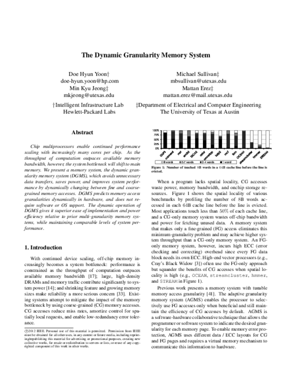
Figure 1: Number of touched 8B words in a 64B cache line before the line is
evicted.
When a program lacks spatial locality, CG accesses
waste power, memory bandwidth, and onchip storage resources. Figure 1 shows the spatial locality of various
benchmarks by profiling the number of 8B words accessed in each 64B cache line before the line is evicted.
Most applications touch less than 50% of each cache line,
and a CG-only memory system wastes off-chip bandwidth
and power for fetching unused data. A memory system
that makes only a fine-grained (FG) access eliminates this
minimum-granularity problem and may achieve higher system throughput than a CG-only memory system. An FGonly memory system, however, incurs high ECC (error
checking and correcting) overhead since every FG data
block needs its own ECC. High-end vector processors (e.g.,
Cray’s Black Widow [3]) often use the FG-only approach
but squander the benefits of CG accesses when spatial locality is high (e.g., OCEAN, streamcluster, hmmer,
and STREAM in Figure 1).
Previous work presents a memory system with tunable
memory access granularity [41]. The adaptive granularity
memory system (AGMS) enables the processor to selectively use FG accesses only when beneficial and still maintain the efficiency of CG accesses by default. AGMS is
a software-hardware collaborative technique that allows the
programmer or software system to indicate the desired granularity for each memory page. To enable memory error protection, AGMS uses different data / ECC layouts for CG
and FG pages and requires a virtual memory mechanism to
communicate this information to hardware.
�2. Adaptive Granularity Memory System
Neither CG-only nor FG-only main memory systems are
ideal for all applications. A CG-only memory system increases cache hit rates, amortizes control overheads, and
benefits from low-redundancy error-control codes for applications with high spatial locality. Many applications, however, exhibit poor spatial locality due to non-unit strides,
indexed gather/scatter accesses, and other complex access
patterns [29, 27, 34]. For applications with low spatial lo-
DBUS (64-bit data + 8-bit ECC)
ABUS
Reg/Demux
We extend AGMS with dynamic mechanisms that offer numerous, substantial benefits. We refer to the resulting system as the Dynamic Granularity Memory System
(DGMS). DGMS supports both CG and FG accesses to a
single, uniform memory space. Eliminating the strict separation of CG and FG accesses enables true dynamic adaptivity and has the potential to increase the overall utility and
to simplify the implementation of an AGMS system.
The data layout for DGMS shares the same memory,
including ECC, between CG and FG memory accesses.
This allows FG accesses to benefit from the same lowredundancy error tolerance as CG accesses, eliminating the
100% FG ECC overhead required for the original AGMS
design [41]. This reduction in error protection overheads
affects the capacity, bandwidth, and power efficiency of FG
accesses.
Because the layout proposed for DGMS permits pages to
service CG and FG accesses simultaneously, it enables the
prediction of access granularities without complicated virtual memory mechanisms. Dynamic locality and granularity speculation allows DGMS to operate as a hardware-only
solution, without application knowledge, operating system
(OS) support, or the need for programmer intervention.
DGMS modifies previously proposed spatial pattern predictors to operate at the main memory interface of a multicore CPU. This study shows dynamic granularity adjustment to be an effective method for improving performance
and system efficiency. DGMS with dynamic spatial locality
prediction provides comparable performance to softwarecontrolled AGMS and demonstrates superior DRAM traffic and power reduction capabilities. Overall, DGMS improves average system throughput by 31% and reduces offchip traffic by 44% and DRAM power by 13%. In addition,
DGMS allows the granularity of a cache line to change with
program phases, resulting in a more flexible and effective
access granularity policy.
The rest of this paper is organized as follows: we
briefly review prior work on adaptive granularity in Section 2, present DGMS in Section 3, describe the evaluation
methodology in Section 4, evaluate DGMS in Section 5,
summarize related work in Section 6, discuss design issues
and future work in Section 7, and conclude our study in Section 8.
X8
x8
x8
x8
x8
x8
x8
x8
x8
SR0
SR1
SR2
SR3
SR4
SR5
SR6
SR07
SR8
Figure 2: Sub-ranked memory with register/demux circuitry.
cality, an FG-only memory system avoids unnecessary data
transfers and utilizes off-chip bandwidth more efficiently.
However, an FG-only memory system requires high ECC
overhead and squanders the benefits of a CG access in programs with high spatial locality.
AGMS is a previously proposed memory system which
combines favorable qualities from both FG and CG accesses. AGMS requires changes to (and collaboration
between) all system levels, from the memory system to
userspace applications. Some implementation details follow; in addition, AGMS requires OS support to track and
propagate page granularity information and mixed granularity memory scheduling at the memory controller. We refer
the reader to [41] for more details.
2.1. Application level interface
Enabling memory protection in AGMS requires different
memory protection schemes for different granularities (see
Section 2.4 for details). Consequently, the processor cannot
adapt the granularity of memory without software support.
AGMS allows the programmer or the software system to
dictate the granularity of each page. This information is
communicated through a set of annotations, hints, compiler
options, and defaults that associate a specific access granularity with every virtual memory page or segment.
2.2. Cache hierarchy
AGMS, with its mixed granularity support, needs to
manage both CG and FG data blocks within the cache hierarchy. AGMS uses a sector cache [22]; each 64B cache
line has eight 8B subsectors to manage 8B FG data blocks
within the cache hierarchy. A sector cache does not increase
address tag overhead but adds some storage overheads for
additional valid and dirty bits (14 bits per 64B cache line).
2.3. Main memory
Main memory uses commodity DDRx DRAM devices.
Since most current systems use CG-only memory accesses,
DDRx memory has evolved to enable high data transfer
rates by increasing the minimum access granularity. The
minimum access granularity is the product of burst length
and channel width.
The burst length of a memory access is dictated by
DRAM technology and cannot be changed by system designers. While high density and low cost DRAM designs
limit DRAM operating speeds, effective I/O data rates have
�Burst 8
64-bit data + 8-bit ECC (SEC-DED)
B0
B1
B2
B3
B4
B5
B6
B7
E 0-7
B8
B9
B10
B11
B12
B13
B14
B15
E 8-15
B16
B24
B32
B40
B48
B56
B17
B25
B33
B41
B49
B57
B18
B26
B34
B42
B50
B58
B19
B27
B35
B43
B51
B59
B20
B28
B36
B44
B52
B60
B21
B29
B37
B45
B53
B61
B22
B30
B38
B46
B54
B62
B23
B31
B39
B47
B55
B63
E 16-23
E 24-31
E 32-39
E 40-47
E 48-55
E 56-63
Core
0
SPP
LPC
$D
Core
0
$I
L2
(a) Coarse-grained (Bx represents the x-th byte in a 64B block, and Ey-z is 8-bit SECDED ECC for data By to Bz.)
B0
B1
E0
E1
B2
B3
B4
B5
B6
B7
E2
E3
E4
E5
E6
E7
B8
B9
B10
B11
B12
B13
B14
B15
E8
E9
E10
E11
E12
E13
E14
E15
E16
E17
B24
B25
E24
E25
B18
B19
B20
B21
B22
B23
E18
E19
E20
E21
E22
E23
B26
B27
B28
B29
B30
B31
E26
E27
E28
E29
E30
E31
(b) Fine-grained (Bx represents the x-th byte in a 64B block, and Ex is 8-bit SEC-DED
ECC for data Bx.)
Figure 3: CG and FG accesses in AGMS [41].
increased throughout DRAM generations. This increase in
transfer bandwidth is achieved by employing an n-bit burst
access: n is 1 in SDRAM, 2 in DDR, 4 in DDR2, and 8
in DDR3. As a result, the minimum access granularity in
a typical 64-bit wide DRAM channel is increasing: 8B in
SDRAM, 16B in DDR, 32B in DDR2, and 64B in DDR3.
To enable an FG access, AGMS leverages a recently proposed sub-ranked memory system that controls individual
DRAM devices within a rank; data access to/from a single
×8 DRAM device is as small as 8B with a burst-8 access in
DDR3. AGMS uses a sub-ranked memory system similar
to HP’s MC-DIMM (multi-core dual in-line memory module) [4, 5]. Figure 2 illustrates a sub-ranked memory system
with a register/demux that can control individual DRAM
devices (see Section 3.2 for more detail).
2.4. Data layout
AGMS uses different data / ECC layouts for CG and FG
pages. The size of ECC grows sub-linearly with the size of
the data it protects; hence, the finer the access granularity,
the larger the ECC overhead. Typically, a CG data block has
12.5% ECC storage overhead; 8-bit ECC (single bit-error
correct and double bit-error detect, or SEC-DED) for every
64-bit data. AGMS applies a similar error coding technique
to a FG data block (8B), requiring 100% ECC overhead –
5-bit ECC provides SEC-DED protection for the data, but
one entire DRAM burst out of a ×8 DRAM chip is needed
to access the ECC information.
Figure 3 compares the data layouts for CG and FG pages.
An FG access can achieve high throughput when spatial locality is low but increases the ECC overhead.
The proposed memory system (DGMS) extends AGMS
and allows it to act without OS or programmer support;
adaptive granularity is provided completely in hardware,
without a priori application knowledge or programmer intervention. DGMS uses a unified data / ECC layout that
…
L2
LPC
GPC
B16
B17
$I
SPP
LPC
$D
$I
L2
Last Level Cache
8-bit data + 5-bit SEC-DED or 8-bit DEC
Burst 8
$D
SPP
Core
0
Memory
Controller
Sub-ranked Memory
Figure 4: A Chip-Multiprocessor (CMP) architecture with DGMS.
permits a physical memory location to service both CG and
FG accesses simultaneously. This unified data layout enables the prediction of access granularities without complicated virtual memory mechanisms. Locality and granularity
speculation, in turn, allow DGMS to operate without external software or programmer support.
3. Dynamic Granularity Memory System
Figure 4 shows a chip-multiprocessor (CMP) architecture with DGMS; each core has a spatial pattern predictor (SPP) and a local prediction controller (LPC). In addition, a global prediction controller (GPC) at the memory controller adaptively tunes the local prediction results.
We describe the ECC scheme and DRAM data layout used
for DGMS in Section 3.1 and then detail its changes to the
AGMS memory system in Section 3.2. The specifics of spatial locality prediction and dynamic granularity adjustment
are described in Section 3.3.
3.1. Data layout
We encode the data within each 64B data chunk differently such that each 8-bit SEC-DED ECC protects the
8B transmitted out of a single DRAM chip over all bursts.
The eight bytes of DGMS ECC protect the full 64B data
chunk with the same redundancy overhead as the conventional CG-only system. Since each 8-bit SEC-DED ECC
protects an independent DRAM chip, the layout supports
both CG and FG accesses. Figure 5(a) illustrates how an
FG request is serviced with the proposed data layout.
Memory traffic with many independent accesses can
negatively impact the performance of the proposed data layout (Figure 5(a)) due to bank conflicts in the ECC DRAM
chip. In order to avoid such contention, we spread ECC
blocks across sub-ranks in a uniform, deterministic fashion,
similar to RAID-5 [28]. We use the residue modulo 9 of the
DRAM column address bits (next to the cache line offset)
for distributing ECC blocks across sub-ranks. We can implement the mod-9 residue generator using efficient parallel
designs of the form [2a + 1; a ∈ N] [37].
DRAM read: A CG read in DGMS is identical to that
of a conventional, CG-only system; the memory controller
�64-bit data
8-bit ECC (SEC-DED)
V D
Burst 8
Tag
B0
B1
B8
B9
B16
B17
B24
B25
B32
B33
B40
B41
B48
B49
B56
B57
E 0-7
E 8-15
B2
B3
B4
B5
B6
B7
B10
B11
B12
B13
B14
B15
B18
B19
B20
B21
B22
B23
B26
B27
B28
B29
B30
B31
B34
B35
B36
B37
B38
B39
B42
B43
B44
B45
B46
B47
B50
B51
B52
B53
B54
B55
B58
B59
B60
B61
B62
B63
E 16-23
E 24-31
E 32-39
E 40-47
E 48-55
E 56-63
Cache Line
8B
8B
8B
8B
8B
ECC
8B
8B
8B
8B
8B
ECC
8B
8B
8B
8B
8B
8B
8B
ECC
8B
8B
8B
8B
8B
8B
8B
ECC
8B
8B
8B
8B
8B
8B
8B
ECC
8B
8B
8B
8B
8B
8B
8B
ECC
8B
8B
8B
8B
8B
8B
8B
ECC
8B
8B
8B
8B
8B
8B
8B
ECC
8B
8B
8B
8B
8B
8B
8B
ECC
8B
8B
SR 0
SR 1
SR 2
8B
8B
8B
8B
SR 3 SR 4
SR 5
SR 6
(b) Spreading ECC locations
8B
8B
SR 7
SR 8
Figure 5: The data layout used by DGMS to support multiple access granularities and the method used to lessen bank conflicts in the ECC DRAM chip.
fetches a 72B block including data and ECC. An FG read
in DGMS is different. The memory controller accesses two
DRAM chips: one for 8B data and the other for 8B ECC.
Unlike AGMS, this 8B ECC block can detect and correct
errors in other data words, which are potentially read later.
For this reason, we retain the ECC information of not-yetfetched words onchip in the invalid subsectors of each line.
Figure 6(a) illustrates how data words and ECC information are stored in a sectored cache line. In this example,
the memory controller fetches only 3 words (and ECC) from
DRAM, and the invalid subsectors store the ECC of the notyet-fetched data words. When a subsector miss occurs, the
L2 cache controller sends the cached ECC from the invalid
subsector to the memory controller along with the FG request. Thus, the memory controller fetches only data and
does error checking and correcting as usual, sourcing the
ECC from the cache rather than re-fetching it.
Compared to AGMS (every FG read has an associated
ECC block), DGMS can significantly reduce ECC traffic
when more than one word in a cache line is accessed. Note
that this mechanism does not change the cache coherence
mechanism and does not complicate cache management.
Invalid subsectors simply store ECC information for future
references, reducing ECC traffic.
DRAM write: An FG DRAM write-back updates an 8B
data block as well as an 8B ECC block. The memory controller must update the ECC with new information corresponding to the words being written, but should not change
the ECC information that corresponds to invalid subsectors
in the cache line being written back. Figure 6(b) shows how
ECC for valid words is encoded, combined with the cached
ECC of invalid subsectors, and written out to DRAM. If
a dirty write-back has only a few dirty words, but the lo-
V D
ECC
V D
ECC
V D
ECC
V D
V D
Data
ECC
DEC
ECC
ECC
DEC
D
x8
x8
x8
x8
x8
x8
x8
x8
D
x8
Reg/Demux
8B
8B
ECC
DEC
ECC
(a) Read
V D
Tag
V D
Data
Data
ECC
ENC
ECC
ENC
x8
x8
V D
ECC
V D
ECC
V D
ECC
V D
ECC
V D
Data
V D
ECC
Cache Line
ECC
ENC
ABUS
D
D
x8
x8
x8
x8
x8
x8
x8
Reg/Demux
8B
8B
V D
Data
ABUS
(a) Proposed data layout (Bx represents the x-th byte in a 64B block, and Ey-z is 8-bit
SEC-DED ECC for data By to Bz.)
8B
V D
Data
(b) Write
Figure 6: DRAM read/write examples in DGMS.
cal or global prediction control dictates a CG access (discussed in Section 3.3.2), then the memory controller uses
write masks to avoid overwriting unchanged or unfetched
data words in DRAM.
3.2. Main memory
We use a sub-ranked memory system similar to MCDIMM [4, 5] to enable FG memory accesses. This subranked memory system places a register/demux to control
each DRAM chip independently, providing 8B access granularity with DDR3 burst-8 accesses.
In order to maximize data bus (DBUS) utilization with
FG requests, both AGMS and DGMS use double data rate
signaling for increased address bus (ABUS) bandwidth.
Figure 7(a) illustrates the partitioned register/demux presented in AGMS [41], which statically separates sub-ranks
into multiple partitions. This partitioned register/demux
ABUS architecture works well for AGMS; an FG access,
fetching 8B data and 8B ECC, is served by one command to
two neighboring sub-ranks in the same static partition, and
the memory controller can issue two independent accesses
per cycle, one for each partition.
DGMS uses the unified data / ECC layout presented
in Section 3.1; an FG access can be served by any combination of two sub-ranks since ECC data can now be in any
sub-rank as in Figure 5(b). Such a layout is not a good fit
for the partitioned register/demux system used by AGMS.
�Load/Store
Partition 0
SR0
SR1
ABUS
SR2
SR3
Clk
SR1
Tag Status
Data
Used
ABUS
Double
Data
Rate
Clk
SR3
..
.
..
.
..
.
SR7
SR7
Clk
SR8
SR8
Reg/Demux
Partition 1
(a) Partitioned reg/demux
L1 Data Cache
SR6
SR6
(b) Unconstrained reg/demux
Status Idx Pattern
..
.
..
.
..
.
..
.
Request To L2
01000000
00001000
00001110
01001100
..
.
11010001
01110000
Evicted or
Subsector miss
CPT
Pattern
SR5
SR5
Reg/Demux
DA
00110000
11010001
SR4
SR4
Clk
+
Idx
00101101
01001011
00001000
10000000
SR2
PHT
F
T
ModeLPC
Double
Data
Rate
PC
Update CPT
SR0
PHT hit
F
Demanded word
T
11111111
Avg. Ref. Word > 3.75
Figure 7: Sub-ranked DRAM (2× ABUS) with register/demux circuitry.
LPC
When DGMS data and its ECC fall in different partitions,
the memory controller must issue two separate commands
for one FG request, doubling ABUS bandwidth consumption.
To mitigate the inefficiency of partitioned register/demux
and to simplify scheduling, we use an unconstrained register/demux architecture, shown in Figure 7(b). This architecture is able to dispatch any two commands to disjoint
sub-ranks each cycle.
3.3. Dynamic granularity adjustment
The data layout described in Section 3.1 allows DGMS
to eliminate the strict separation between CG and FG pages.
This removes the need for virtual memory support for memory access granularity, making DGMS a hardware-only solution. Adjusting access granularity without software support significantly reduces the barrier to adopting DGMS in
actual designs.
We use a previously suggested hardware predictor that
identifies likely-to-be-referenced words within a cache
line [19, 10]. Since the prior spatial pattern predictors are
designed for a single core, we introduce a two-level prediction control mechanism, considering the potential interference among multiple cores and threads: a local prediction controller (LPC) in each core and a global prediction
controller (GPC) at the memory controller. Section 3.3.1
describes the details of spatial pattern prediction, and Section 3.3.2 illustrates the proposed two-level prediction control mechanism.
3.3.1. Spatial pattern predictor We use the spatial pattern
predictor (SPP) proposed by Chen et al. [10]. The SPP uses
a current pattern table (CPT) and a pattern history table
(PHT) for predicting likely-to-be-referenced word patterns
upon a cache miss. Figure 8 illustrates the organization of
an L1 data cache with the CPT and PHT.
Current pattern table: The CPT keeps track of which
words in each L1 cache line are referenced. A CPT entry
is composed of a bit vector, with a one indicating that the
corresponding word in the cache line was used (Used), and
an index into the pattern history table (Idx). The Used bit
Figure 8: SPP [10] and LPC.
vector is updated on every L1 data cache access and tracks
all words used in the cache line over its lifetime (from cache
fill to eviction).
When an L1 cache line is evicted, the associated CPT entry updates the PHT with the Used bit vector to enable prediction of future usage patterns. The Idx indicates the PHT
entry to be updated. We construct the Idx using the program
counter (PC) and the data address (DA) of the load/store instruction that originally triggered the cache fill. We use a
12-bit PHT Idx and calculate an Idx as follows.
Idx = 0xFFF &
L
(((PC >> 12) PC) << 3 + (0x7 & (DA >> 3)))
Pattern history table: The PHT is a cache-like structure
that maintains recently captured spatial locality information. Although Figure 8 describes the PHT as a directmapped structure, it can be of any associativity. We use a
small, 32-set 8-way set associative PHT (only 768B) in the
evaluation. This small PHT is sufficient because the PHT
tracks the pattern behavior of load/store instructions and
does not attempt to track the large number of cache lines
in the system. The PHT Idx, as shown above, is composed
mostly of PC bits with a few DA bits to account for different alignments (as discussed in [10]). The 12-bit Idx we use
can track 512 different memory instructions (assuming no
aliasing); this is sufficient for the applications we evaluate,
corroborating prior results [10, 19].
When a cache miss occurs, the PHT is queried to get the
predicted spatial pattern. If a PHT miss occurs, a default
prediction is used. A strong default is important for DGMS;
we propose a heuristic based on per-thread spatial locality.
If the average number of referenced words per line is fewer
than 3.75, the immediately requested words are used as the
default prediction. Otherwise, the predictor defaults to a
coarse-grained prediction. This heuristic is based on the observation that fetching approximately 4 or more FG words
is often inefficient due to high control overheads.
3.3.2 Local and global prediction control The SPP
effectively predicts potentially referenced words, thereby
�GPC
Decision
Algorithm 1 Calculating row-buffer hit rate. addr is the
address of a request from L2.
Accesses = Accesses +1
bk = get bank addr( addr )
row = get row addr( addr )
if row 6= row buffer status[ bk ] then
if queue[ bk ] is full then
BankConflicts = BankConflicts +1
oldest row = get row addr( find oldest addr in the queue [ bk ] )
remove all the entries with row addr equal
to the oldest row in the queue[ bk ]
row buffer status[ bk ] = oldest row
if oldest row 6= row then
push the addr into the queue[ bk ]
end if
else
push the addr into the queue[ bk ]
end if
end if
Page Hitr Rate = 1 - (BankConflicts / Accesses)
minimizing off-chip traffic. The goal of DGMS, however,
is to maximize system throughput and power efficiency by
predicting spatial locality in DRAM access streams. As
discussed in AGMS [41], FG memory accesses increase
DRAM control overhead; an overabundance of FG requests
is undesirable even if it reduces the total data traffic. Thus,
we employ a two-level prediction control mechanism that
combines local prediction with global adjustment.
Local prediction controller: The LPC in each core monitors thread access patterns and determines ModeLPC , which
is based upon two metrics: the average number of referenced words per cache line and the row-buffer hit rate (per
thread). The former represents spatial locality within a
cache line, and the latter measures spatial locality across
cache lines. If the average number of referenced words exceeds 3.75 or if the row-buffer hit rate is greater than 0.8,
ModeLPC is set to CG; otherwise, it is set to Transparent.
The spatial pattern predicted by the SPP is ignored if
ModeLPC is CG, but we defer the actual decision to the GPC
at the memory controller to take into account memory requests across all the cores. Thus, ModeLPC is attached to
every request from L1 (both reads and writes) as in Figure 8.
We measure per-thread row-buffer hit rate by observing
traffic just below the last core-private cache (L2 in our case);
after this point in the memory hierarchy, requests from different cores are interleaved, making per-thread observation
difficult. We analyze the row-buffer hit rate of each L2 miss
or eviction using a simple DRAM row-buffer model that
manages a 4-entry scheduling queue per bank (assuming 32
memory banks, a 4kB row-buffer per bank, and FR-FCFS
scheduling [30]). Note that this model does not include
timing and only counts the number of requests and bankconflict requests. Algorithm 1 shows how we count bank
conflicts and estimate the row-buffer hit rate.
Global prediction controller: The GPC at the memory
controller dynamically adjusts the access granularity based
on the memory controller status, SPP predictions, and LPC
N
FRACCG > 0.8
N
Y
FRACCG > 0.6
Y
ModeLPC == CG
Y
N
FG
Transparent
CG
Figure 9: Global prediction decision logic. FRACCG is the fraction of coarsegrained requests in the memory controller queue, and ModeLPC is the LPC’s
decision bundled with the request.
decisions (ModeLPC ). Figure 9 illustrates the GPC decision
logic. When one type of request (CG or FG) dominates the
memory controller queue, the GPC forces incoming transactions to the dominating one (CG or FG mode), ignoring
the SPP. If neither CG nor FG request dominates the memory controller queue, the memory controller follows the decision made by the LPC and the SPP. This global override is
important to maximize memory throughput rather than just
minimize memory traffic.
4. Evaluation Methodology
To evaluate DGMS, we use detailed cycle-based simulation. We integrate the Zesto simulator [23] with DrSim [18],
a detailed DRAM model. This simulation platform supports
all aspects of DGMS, including the sub-ranked memory
systems as well as the register/demux circuitry described
in Section 3.2.
Workloads: We use a mix of several applications
from SPEC CPU2006 [35], PARSEC [7], Olden [9],
SPLASH2 [39], and the HPCS [1] benchmark suites as well
as the GUPS [12] and STREAM [24] microbenchmarks. Our
collection of benchmarks is primarily memory intensive but
also includes some compute-bound applications. Table 1
summarizes the characteristics of the benchmarks. We use 8
identical instances of single-threaded applications to stress
memory systems in a CMP and also run the application
mixes described in Table 2.
We extract a representative region of 100 million instructions from each application for the cycle-based simulations.
We use Simpoint [16] with the SPEC applications and manually skip the initialization phase for the regularly-behaved
applications (Olden, PARSEC, SPLASH2, HPCS, GUPS
and STREAM).
System configurations: Table 3 describes the base system
configuration used for the cycle-based simulations. Note
that we use a system with relatively low off-chip bandwidth
to evaluate DGMS in the context of future systems, where
off-chip bandwidth is likely to be scarce.
Power models: Our main focus is on the memory hierarchy.
We use the detailed power model developed by the Micron
Corporation [2] for DRAM, and CACTI 6 [26] for the cache
hierarchy. Our processor power analysis uses the IPC-based
model suggested by Ahn et al. [4]. In this model, the max-
�Table 1: Benchmark characteristics.
Benchmark suite
SPEC CPU2006
PARSEC
SPLASH2
Olden
HPCS
Microbenchmarks
Application
mcf
omnetpp
bzip2
hmmer
lbm
canneal
streamcluster
OCEAN
mst
em3d
SSCA2
GUPS
STREAM
LLC MPKI
31.3
11.6
3.2
0.87
22.9
17.2
14.5
18.6
41.6
39.4
25.4
174.9
51.9
DRAM page hit rate
19.1
47.8
57.1
91.3
82.6
14.1
86.8
92.6
40.5
27.4
25.5
10.9
96.5
0.8
0.6
0.4
0.2
0.0
Table 3: Simulated base system parameters.
Last-Level caches (LLC)
onchip memory controller
Main memory
4GHz x86 out-of-order core (8 cores)
32kB private, 2-cycle latency, 64B cache line
32kB private, 2-cycle latency, 64B cache line
256kB private for instruction and data,
7-cycle latency, 64B cache line
shared cache, 64B cache line, 8MB,
17-cycle latency, 64B cache line
FR-FCFS scheduler [30],
64-entry read queue, 64-entry write queue,
XOR-based bank, sub-rank mapping [42]
one 72-bit wide DDR3-1066 channel,
64-bit data and 8-bit ECC,
×8 DRAM chips, 8 banks per rank,
4 ranks per channel,
parameters from Micron 1Gb DRAM [25]
imum power per core is estimated to be 16.8W based on a
32nm Xeon processor model using McPAT v0.7 [20]; half
of the maximum power is assumed to be fixed (including
leakage), and the other half is proportional to IPC. To account for the additional overhead for sector caches, register/demux circuitry, and ECC logic, we add a conservative
10% power penalty to the LLC and DRAM power in AGMS
and DGMS. We do not add additional power for the SPP
since it is a very small structure – only 768B per core.
Metrics: We use the weighted speedup (WS) [13] to measure system throughput with multiprogrammed workloads
as shown in Equation 1: N is the number of cores,
IP Cishared is the IPC of the i-th application when running
with other applications, and IP Cialone is the IPC of the i-th
application when running alone in the CMP.
WS =
N
−1
X
i=0
IP Cishared
IP Cialone
Average granularity
MEDIUM
MEDIUM
MEDIUM
COARSE
MEDIUM
FINE
COARSE
COARSE
FINE
FINE
FINE
FINE
COARSE
1.0
SSCA2 ×2, mst ×2, em3d ×2, canneal ×2
SSCA2 ×2, canneal ×2, mcf ×2, OCEAN ×2
canneal ×2, mcf ×2, bzip2 ×2, hmmer ×2
mcf ×4, omnetpp ×4
SSCA2 ×2, canneal ×2, mcf ×2, streamcluster ×2
Processor core
L1 I-caches
L1 D-caches
L2 caches
DRAM traffic
HIGH
HIGH
LOW
LOW
HIGH
HIGH
HIGH
HIGH
HIGH
HIGH
HIGH
HIGH
HIGH
1.2
Table 2: Application mix for 8-core simulations.
MIX1
MIX2
MIX3
MIX4
MIX5
Average words per cache line
3.59
3.22
3.63
7.93
3.92
1.87
7.24
6.68
2.30
2.62
2.63
1.84
7.99
(1)
We also report the system power efficiency in terms of
throughput (WS) per Watt. System power includes the aggregate power of cores, caches, and DRAM. Power efficiency, rather than energy efficiency, is appropriate for this
Predicted, but Not Referenced
Not predicted, but Referenced
Predicted & Referenced
PHT Hit Rate
SSCA2
canneal
em3d
SSCA2
canneal
em3d
mst
mst
gups
gups
mcf
mcf
omnetpp
lbm
omnetpp
lbm
OCEAN streamcluster
stream
OCEAN
s-cluster stream
Figure 10: PHT hit rate and prediction accuracy in the SPP.
study because of our multiprogrammed simulation methodology. While we collect statistics such as IPC for a fixed
number of instructions from each program, the amount of
time over which statistics are gathered varies to ensure fair
contention (additional details in the AGMS paper [41]).
5. Results and Discussion
In this section, we evaluate DGMS. We first discuss the
the accuracy of the spatial pattern predictor in Section 5.1
and then investigate the effectiveness of local and global
prediction in Section 5.2. We present the performance and
power impacts of DGMS in Section 5.3.
5.1. Spatial pattern predictor accuracy
In order to measure the accuracy of the SPP, we run
simulations without local and global prediction. Figure 10
shows the PHT hit rate and prediction accuracy. In most applications (except omnetpp and streamcluster), PHT
hit rate is high and spatial prediction is very accurate – exhibiting a high percentage of “Predicted & Referenced” and
relatively low “Predicted, but Not Referenced” and “Not
predicted, but Referenced” accesses.
To better explore the SPP design space, we run another
simulation with a larger PHT (64-set and 32-way set associative); the results are almost the same as in Figure 10, except for the benchmark omnetpp. In omnetpp, the larger
PHT increases PHT hit rate from 65% to 81%. Overall
performance improvement using a larger PHT is marginal,
however, so we do not use a large PHT in this study. Another notable application is streamcluster, which suffers from many “Not predicted, but referenced” accesses.
This low prediction accuracy results in significant performance degradations when spatial prediction is used alone.
�Weighted Speedup
6
5
4
3
2
1
0
Weighted
Weighted
Speedup
Speedup
6
5
CG
(Hit Rate)
Local-control (Hitrate)
Local + WB control
SSCA2 canneal
canneal em3d
SSCA2
em3d
mst
mst
gups
gups
SPP-only
Local-control (AvgRefWords)
Global-control
mcf omnetpp
omnetpp lbm
lbm OCEAN
OCEAN s-cluster
s-cluster stream
MIX1
mcf
stream MIX1
Figure 11: Effects of SPP, LPC, and GPC.
MIX2
MIX2
CG
AGMS
D-AGMS-profiling
DGMS-profiling
D-AGMS-prediction
DGMS-prediction
MIX3
MIX3
MIX4
MIX4
MIX5
MIX5
4
3
2
1
0
SSCA2 canneal
canneal em3d
em3d
mst
gups
mcf omnetpp
omnetpp lbm
lbm OCEAN
OCEAN s-cluster
s-cluster stream
stream
MIX1
MIX2
MIX3
MIX4
MIX5
SSCA2
mst
gups
mcf
MIX1
MIX2
MIX3
MIX4
MIX5
Figure 12: System throughput. Results based on partitioned register/demux. Stacked black bars represent additional gain due to unconstrained register/demux.
As such, streamcluster illustrates the importance of
using a combination of control mechanisms to achieve robust performance gains across different workloads.
5.2. Effects of local and global control prediction
Figure 11 presents the effects of local and global prediction: CG is the CG-only baseline; SPP-only is DGMS
with only spatial prediction (no local and global predictors);
Local-control (hit rate) is DGMS with local prediction control using hit rate based decisions only; Local-control (AvgRefWords) uses local prediction control basing decisions
on the average referenced words; Local + WB control uses
full local prediction control (based on both hit rate and average referenced words), controlling write-backs as well; and
Global control uses the combined local and global prediction control.
In most applications, SPP-only works well and local/global prediction control does not significantly alter performance. However, SPP-only degrades applications with high spatial locality (lbm, OCEAN, and
streamcluster). While hit rate based local control
works well with lbm, it is not sufficient for OCEAN and
streamcluster, in which applying local prediction control to write-backs is very effective. Experiments using only
hit-rate based local prediction combined with write-back
control fail to achieve performance comparable to the CG
baseline; the row-buffer hit rate of streamcluster (0.7)
is below the threshold (0.8) in the LPC, and some local prediction based on the number of referenced words is needed.
MIX2 is an interesting case; it is negatively impacted by
the most sophisticated local prediction (Local + WB control). In MIX2, only OCEAN has high spatial locality, while
the other (more memory intensive) applications have low
spatial locality. OCEAN generates CG requests, negatively
impacting the memory controller (even if CG is an optimal
decision for OCEAN). Though the memory controller can
split a CG request into FG requests, it is not as effective as
serving a single granularity (if possible). The global prediction control detects and corrects granularity inefficiencies
by monitoring the queue status at the memory controller
and disabling the LPC’s decisions to achieve better performance.
5.3. Performance and power impacts
Figure 12 compares the system throughput of the CG
baseline, AGMS [41], DGMS-profiling (DGMS with the
same static granularity decision as in AGMS), and DGMSprediction (DGMS with spatial pattern prediction and local/global prediction control).
Effects of register/demux configuration: We use the partitioned register/demux in both AGMS and DGMS; the
stacked black bars represent additional gains possible with
an unconstrained register/demux. In AGMS, an FG request
accesses two DRAM chips (one for data and the other for
ECC), both in the same partition; hence, the partitioned register/demux performs as effective as the unconstrained register/demux. With the DGMS data layout, however, the benefits of the unconstrained register/demux are apparent. It
provides high effective ABUS bandwidth and has the greatest impact on applications that have high ABUS utilization, achieving a throughput improvement of 16–24% for
SSCA2, em3d, GUPS, omnetpp, MIX2, and MIX5.
Low spatial locality applications: Applications such as
SSCA2, canneal, em3d, mst, and GUPS have very low
spatial locality and typically only access one or two words
per cache line. As a result, adaptive granularity significantly improves system throughput: AGMS by 20 − 220%,
DGMS-profiling by 20 − 180%, and DGMS-prediction by
�stream
MIX1
MIX2
MIX3
MIX4
CG
AGMS
DGMS
CG Data
CG
AGMS
DGMS
CG
AGMS
DGMS
CG
AGMS
DGMS
OCEAN s-cluster
CG ECC
CG
AGMS
DGMS
lbm
FG Data
CG
AGMS
DGMS
omnetpp
CG
AGMS
DGMS
mcf
CG
AGMS
DGMS
gups
FG ECC
CG
AGMS
DGMS
mst
CG
AGMS
DGMS
CG
AGMS
DGMS
CG
AGMS
DGMS
em3d
CG
AGMS
DGMS
canneal
CG
AGMS
DGMS
SSCA2
CG
AGMS
DGMS
CG
AGMS
DGMS
Traffic [Bytes/Instr]
24.4
8
6
4
2
0
MIX5
CG
AGMS
DGMS
MIX1
MIX2
MIX3
MIX4
CG
AGMS
DGMS
CG
AGMS
DGMS
CG
AGMS
DGMS
CG
AGMS
DGMS
OCEAN s-cluster stream
Background
CG
AGMS
DGMS
lbm
Refresh
CG
AGMS
DGMS
omnetpp
CG
AGMS
DGMS
mcf
ACT/PRE
CG
AGMS
DGMS
gups
CG
AGMS
DGMS
RD/WR
CG
AGMS
DGMS
mst
I/O
CG
AGMS
DGMS
SSCA2 canneal em3d
CG
AGMS
DGMS
CG
AGMS
DGMS
Ref/Demux
Reg/Demux
CG
AGMS
DGMS
10
8
6
4
2
0
CG
AGMS
DGMS
DRAM Power [W]
Figure 13: Off-chip traffic. AGMS with the partitioned register/demux and DGMS with the unconstrained register/demux.
MIX5
Figure 14: DRAM power.
18 − 180%. The reason why AGMS consistently outperforms DGMS is that AGMS exhibits more regular access
patterns. FG requests in AGMS are aligned in neighboring sub-ranks, whereas the unified data / ECC layout randomizes the ECC for FG blocks in DGMS. As a result, the
bank conflict rate increases significantly with the DGMS
data layout. For example, the DRAM row-buffer hit rate
of SSCA2 is 10% with AGMS but drops to almost 4% with
DGMS-profiling, although both configurations use the same
profile data for granularity decisions.
Effects of new data/ECC layout: The new layout of
DGMS has advantages over that of AGMS and can significantly reduce ECC traffic. DGMS makes a single ECC access for all subsectors in the cache, while AGMS requires a
separate ECC access for each sector. The benefits of fewer
ECC accesses are very apparent when considering DRAM
traffic (described later in this subsection).
It is hard to isolate the throughput gain of fetching less
ECC from the degradation due to increased DGMS bank
conflicts. The results of GUPS and mcf, however, provide some useful insights in this area. GUPS accesses 1
word per cache line, so DGMS cannot take advantage of
reduced ECC traffic. As such, the performance degradation of DGMS (relative to AGMS) is mainly due to the increased bank conflicts from its memory layout. In contrast
to GUPS, mcf significantly benefits from DGMS, outperforming AGMS by 30%. The mcf application accesses an
average of 3.6 words per cache line, such that the new data
layout of DGMS significantly reduces ECC traffic.
High spatial locality applications: Applications that have
high spatial locality, such as libquantum, OCEAN,
streamcluster (s-cluster in the graph), and STREAM,
do not benefit much from adaptive granularity. The profiler marks nearly all pages as CG in AGMS and DGMS-
profiling. In DGMS-predictor, the GPC (global prediction
controller) forces CG accesses almost exclusively.
One interesting case is lbm, which accesses 2–3 words
per cache line. FG accesses effectively reduce off-chip traffic, as expected. However, lbm’s memory access streams
show very high row-buffer hit rates, and simply using CG
requests (chosen through local prediction control) yields
better performance. However, with 4× ABUS bandwidth
(twice the address bandwidth of the chosen configuration),
lbm without local/global prediction control results in 5%
higher performance than CG.
Off-chip traffic and DRAM power: Figure 13 compares
the off-chip traffic of the CG baseline with AGMS and
DGMS-prediction. While both AGMS and DGMS reduce
off-chip traffic (36% lower in AGMS and 44% lower in
DGMS), DGMS shows consistently lower traffic than that
of AGMS with one exception. This is due to the data layout
of DGMS, which allows only 1 ECC word for a 64B cache
line regardless of how many words are referenced. Hence,
DGMS can reduce ECC traffic when more than 1 word is
accessed, as with mcf and omnetpp. SPP over-fetches in
em3d, yielding slightly more traffic than that of AGMS but
still generates radically less traffic than the CG baseline.
DGMS also reduces DRAM power as shown in Figure 14. Compared to the CG baseline, AGMS reduces
DRAM power by 3% and DGMS by 13%, on average.
In applications with high spatial locality (libquantum,
OCEAN, streamcluster, and STREAM), AGMS and
DGMS use 10% higher DRAM power than the CG baseline due to the register/demux.Note that the 10% penalty
for the register/demux is a very conservative estimate, and
the CG baseline will have a similar penalty when registered
DIMMs or Buffer-on-Boards are used.
Power efficiency: Figure 15 shows the normalized throughput per unit power. We measure the whole-system power in-
�Normalized
Throughput/Power
3.2 2.8
2.0
CG
AGMS
DGMS
1.5
1.0
0.5
0.0
SSCA2
canneal
em3d
mst
gups
mcf
omnetpp
lbm
OCEAN s-cluster
stream
MIX1
MIX2
MIX3
MIX4
MIX5
Weighted Speedup
Figure 15: Power efficiency.
7
6
5
4
3
2
1
0
CG
DGMS-prediction (ECC)
DGMS-prediction (No ECC)
SSCA2
SSCA2 canneal
canneal em3d
em3d
AGMS (ECC)
DGMS-profiling (No ECC)
mst
gups
mcf
MIX1
mst
gups
mcf omnetpp
omnetpp lbm
lbm OCEAN
OCEAN s-cluster
s-cluster stream
stream
MIX1
Figure 16: System throughput of AGMS and DGMS with and without ECC.
cluding cores, caches, and DRAM for estimating power efficiency. Though DGMS reduces DRAM power consumption by 13% on average, the system power is dominated
by the processor cores: 8 cores consume 69 − 72W out of
around 80W of total system power. Therefore, the system
power efficiency is heavily correlated to the system throughput. DGMS improves power efficiency when compared to
the CG baseline by 30% on average and by factors of nearly
2 and 3 with canneal and GUPS, respectively.
DGMS without ECC: We also evaluate DGMS without
ECC. When ECC is disabled, DGMS can further improve
system throughput since it does not suffer from ECC rowbuffer interference and bank conflicts. Figure 16 presents
the system throughput of CG, AGMS (with ECC), DGMSprediction (with ECC), DGMS-profiling (without ECC),
and DGMS-prediction (without ECC). Note that DGMSprofiling and AGMS are the exact same design in a system
without ECC.
Without ECC support, both DGMS-profiling and
DGMS-prediction outperform DGMS with ECC. Furthermore, dynamic locality prediction (DGMS-prediction)
garners additional gains relative to static profilingbased DGMS-profiling and AGMS (canneal, omnetpp,
MIX1, and MIX2). MIX3, for which DGMS with ECC
performs worse than CG, is now improved by 29%. Overall, DGMS-prediction without ECC provides an additional
gain of 22% compared to DGMS-prediction with ECC and
improves system throughput by 55% over the CG baseline.
6. Related Work
Adaptive granularity: DGMS is based on prior work,
AGMS [41], and shares many features in common with
AGMS. DGMS uses a unified data/ECC layout to allow
multi-granularity memory accesses to the same memory
space, obviate software support, and enable dynamic granu-
MIX2
MIX2
MIX3
MIX3
MIX4
MIX4
MIX5
MIX5
larity adaptation. DGMS is a hardware-only solution which
retains the main advantages of AGMS while simultaneously
reducing implementation difficulties.
DRAM systems: The idea of sub-ranked memory is
described in many recent proposals, including Rambus’s threaded-module [38], mini-ranks [43], HP’s MCDIMM [5, 4], and Convey’s S/G DIMM [8]. Most of these
approaches focus on reducing the energy of CG accesses.
S/G DIMM [8] is designed for FG accesses, but no detailed
quantitative analysis is provided.
Caches: We evaluate DGMS with sector caches [22] to
manage both CG and FG data in the cache hierarchy.
A more advanced architecture, such as a decoupled sectored cache [32], a pool-of-sectors cache [31], or a spatio/temporal cache [15], can better manage FG data in the
cache hierarchy. The simple sector cache is used because
it enables a fair comparison among DGMS, AGMS, and
a conventional CG-only memory system and isolates improvements to the memory interface.
Spatial locality prediction: We use the prior designs of
spatial footprint prediction [19] and spatial pattern prediction [10]. We adapt this idea to the main memory interface
and introduce adaptive local and global overriding of spatial
locality prediction to match the needs of multigranularity
memory access scheduling in modern DRAM systems.
7. Caveats and Future Work
While the alternative data layout proposed for DGMS
has substantive, practical advantages, its adoption complicates two possible DRAM system optimizations: DRAM
critical word first and single-pin failure protection with
SEC-DED ECC.
With the proposed new layout, it is no longer possible to
access the critical word first at the DRAM boundary. ECC
information can only be checked after an entire burst has
�16B data block
CRC
Parity
Burst 16
Figure 17: A simple erasure code that provides chipkill-level protection for
DGMS. A 7-bit CRC provides error detection for each 16B data block. When
an error occurs, the CRC locates the erroneous sub-rank and horizontal parity
corrects the error. The remaining bits in the 16B CRC block can be used for
error detection in the CRC chip itself and/or in the parity chip. One caveat is
that a write back requires a read-modify-write operation to correctly update the
parity information.
been received, rather than after each DRAM beat, which
is possible with conventional mapping. We simulated the
SPEC CPU2006 benchmarks on a 4-core CMP with and
without critical word first support. The results show that
DRAM critical word first improves system throughput by
less than 1% in all simulated cases.
The second implementation issue is that the proposed
layout cannot tolerate a single pin failure, which is possible
with the conventional layout. A single pin failure corrupts
multiple (up to 8) bits within an FG data block, whereas the
commonly used SEC-DED ECC can only correct a single
bit failure. In the conventional design, a pin failure manifests as a single bit failure in every beat and can be corrected
by SEC-DED ECC.
Tolerating a pin failure, however, is not the primary goal
of a SEC-DED system, which is designed for soft errors.
For strong reliability guarantees against permanent failures,
some variant of chipkill-correct is typically used [11]. We
sketch a possible chipkill-correct configuration with DGMS
and present it in Figure 17. Note that the minimum access
granularity increases to 16B, but overall redundancy level
is unchanged. Maintaining both chipkill-correct protection
level and 8B access granularity requires either increasing
the redundancy level or employing techniques such as Virtualized ECC [40], which decouples ECC information from
data storage. While further work remains to investigate alternative error protection schemes with DGMS, levels of error protection stronger than SEC-DED are clearly feasible.
A detailed evaluation of such designs is beyond the scope
of this paper.
8. Conclusion
In this paper, we present DGMS, a hardware-only solution to dynamically adapt memory access granularities.
Adapting the access granularity utilizes scarce bandwidth
more efficiently by dynamically balancing traffic and control overheads. DGMS uses a new data / ECC layout combined with spatial footprint prediction to remove the need
for software interaction and control. Taking software out
of the loop increases the utility of the adaptive granularity
concept as well as its potential impact.
In our experiments, DGMS improves the system
throughput of memory-intensive applications with low or
medium spatial locality by 31%, while reducing DRAM
power by 13% and DRAM traffic by 44%. DGMS generally matches the execution characteristics of traditional CGonly systems for applications with high spatial locality. The
dynamic granularity predictor is very accurate and consistently outperforms software-profiling based granularity decisions. The benefits of dynamic prediction over static profiling are more significant when considering DRAM traffic
and power.
We will explore memory scheduling algorithms that are
more suitable for mixed-granularity access and will investigate better global feedback mechanisms for choosing access
granularities. We also plan a more detailed design and evaluation of strong chipkill-correct schemes that build on the
initial proposal discussed in the previous section.
Finally, while we evaluate dynamic granularity in the
context of main memory, we believe that DGMS can be applied to many other systems where interface bandwidth is
constrained. For example, DGMS can be particularly useful for memory architectures such as disaggregated memory [21], Violin memory [36], and PCIe-attached phasechange memory [6], all of which have a relatively lowbandwidth interface.
9. Acknowledgments
This work is supported, in part, by the following organizations: The National Science Foundation under Grant
#0954107, Intel Labs University Research Research Office
for the Memory Hierarchy Innovation program, and The
Texas Advanced Computing Center.
References
[1] HPCS
scalable
synthetic
compact
application
(SSCA).
http://www.highproductivity.org/
SSCABmks.htm.
[2] Calculating memory system power for DDR3. Technical Report TN-41-01, Micron Technology, 2007.
[3] D. Abts, A. Bataineh, S. Scott, G. Faanes, J. Schwarzmeier,
E. Lundberg, M. Byte, and G. Schwoerer. The Cray Black
Widow: A highly scalable vector multiprocessor. In Proc. the
Int’l Conf. High Performance Computing, Networking, Storage, and Analysis (SC), Nov. 2007.
[4] J. H. Ahn, N. P. Jouppi, C. Kozyrakis, J. Leverich, and R. S.
Schreiber. Future scaling of processor-memmory interfaces.
In Proc. the Int’l Conf. High Performance Computing, Networking, Storage and Analysis (SC), Nov. 2009.
[5] J. H. Ahn, J. Leverich, R. Schreiber, and N. P. Jouppi. Multicore DIMM: An energy efficient memory module with independently controlled DRAMs. IEEE Computer Architecture
Letters, 8(1):5–8, Jan. - Jun. 2009.
[6] A. Akel, A. M. Caulfield, T. I. Mollov, R. K. Gupta, and
S. Swanson. Onyx: A protoype phase-change memory storage array. In Proc. the 3rd USENIX conference on Hot topics
in storage and file systems (Hot Storage), Jun. 2011.
�[7] C. Bienia, S. Kumar, J. P. Singh, and K. Li. The PARSEC
benchmark suite: Characterization and architectural implications. Technical Report TR-811-08, Princeton Univ., Jan.
2008.
[8] T. M. Brewer. Instruction set innovations for the Convey HC1 computer. IEEE Micro, 30(2):70–79, 2010.
[9] M. C. Carlisle and A. Rogers. Software caching and computation migration in Olden. Technical Report TR-483-95,
Princeton University, 1995.
[10] C. Chen, S.-H. Yang, B. Falsafi, and A. Moshovos. Accurate
and complexity-effective spatial pattern prediction. In Proc.
the 10th Int’l Symp. High-Performance Computer Architecture (HPCA), Feb. 2004.
[11] T. J. Dell. A white paper on the benefits of chipkill-correct
ECC for PC server main memory. IBM Microelectronics Division, Nov. 1997.
[12] Earl Joseph II. GUPS (giga-updates per second) benchmark. http://www.dgate.org/˜brg/files/dis/
gups/.
[13] S. Eyerman and L. Eeckhout. System-level performance
metrics for multiprogram workloads. IEEE Micro, 28(3):42–
53, 2008.
[14] X. Fan, W.-D. Weber, and L. A. Barroso. Power provisioning
for a warehouse-sized computer. In Proc. the 34th Ann. Int’l
Symp. Computer Architecture (ISCA), Jun. 2007.
[15] A. Gonzalez, C. Aliagas, and M. Valero. A data cache with
multiple caching strategies tuned to different types of locality.
In Proc. the Int’l Conf. Supercomputing (ICS), Jul. 1995.
[16] G. Hamerly, E. Perelman, J. Lau, and B. Calder. SimPoint
3.0: Faster and more flexible program analysis. In Proc.
the Workshop on Modeling, Benchmarking and Simulation
(MoBS), Jun. 2005.
[17] J. Huh, D. Burger, and S. Keckler. Exploring the design
space of future cmps. In Parallel Architectures and Compilation Techniques, 2001. Proceedings. 2001 International
Conference on, pages 199 –210, 2001.
[18] M. K. Jeong, D. H. Yoon, and M. Erez. DrSim: A platform
for flexible DRAM system research. http://lph.ece.
utexas.edu/public/DrSim.
[19] S. Kumar and C. Wilkerson. Exploiting spatial locality in
data caches using spatial footprints. In Proc. the 25th Ann.
Int’l Symp. Computer Architecture (ISCA), Jun. 1998.
[20] S. Li, J. H. Ahn, R. D. Strong, J. B. Brockman, D. M.
Tullsen, and N. P. Jouppi. McPAT: An integrated power, area,
and timing modeling framework for multicore and manycore
architectures. In Proc. the 42nd Ann. IEEE/ACM Int’l Symp
Microarchitecture (MICRO), Dec. 2009.
[21] K. Lim, J. Chang, T. Mudge, P. Ranganathan, S. K. Reinhardt, and T. F. Wenisch. Disaggregated memory for expansion and sharing in blade servers. In Proc. the 36th Int’l Symp.
Computer Architecture (ISCA), Jun. 2009.
[22] J. S. Liptay. Structural aspects of the system/360 model 85,
part II: The cache. IBM Systems Journal, 7:15–21, 1968.
[23] G. H. Loh, S. Subramaniam, and Y. Xie. Zesto: A cycle-level
simulator for highly detailed microarchitecture exploration.
In Proc. the Int’l Symp. Performance Analysis of Software and
Systems (ISPASS), Apr. 2009.
[24] J. D. McCalpin. STREAM: Sustainable memory bandwidth in high performance computers. http://www.cs.
virginia.edu/stream/.
[25] Micron Corp. Micron 1 Gb ×4, ×8, ×16, DDR3 SDRAM:
MT41J256M4, MT41J128M8, and MT41J64M16, 2006.
[26] N. Muralimanohar, R. Balasubramonian, and N. P. Jouppi.
CACTI 6.0: A tool to model large caches. Technical Report
HPL-2009-85, HP Labs, Apr. 2009.
[27] R. C. Murphy and P. M. Kogge. On the memory access patterns of supercoputer applications: Benchmark selection and its implications. IEEE Transactions on Computers,
56(7):937–945, Jul. 2007.
[28] D. A. Patterson, G. Gibson, and R. H. Katz. A case for redundant arrays of inexpensive disks (RAID). In Proc. the ACM
SIGMOD International Conference on Management of data,
Jun. 1988.
[29] M. K. Qureshi, M. A. Suleman, and Y. N. Patt. Line distillation: Increasing cache capacity by filtering unused words in
cache lines. In Proc. the 13th Int’l Symp. High Performance
Computer Architecture (HPCA), Feb. 2007.
[30] S. Rixner, W. J. Dally, U. J. Kapasi, P. R. Mattson, and J. D.
Owens. Memory access scheduling. In Proc. the 27th Ann.
Int’l Symp. Computer Architecture (ISCA), Jun. 2000.
[31] J. B. Rothman and A. J. Smith. The pool of subsectors cache
design. In Proc. the 13th Int’l Conf. Supercomputing (ICS),
Jun. 1999.
[32] A. Seznec. Decoupled sectored caches: Conciliating low
tag implementation cost. In Proc. the 21st Ann. Int’l Symp.
Computer Architecture (ISCA), Apr. 1994.
[33] C. Slayman.
Impact and mitigation of DRAM and
SRAM soft errors.
IEEE SCV Reliability Seminar
http://www.ewh.ieee.org/r6/scv/rl/
articles/Soft%20Error%20mitigation.pdf,
May 2010.
[34] S. Somogyi, T. F. Wenisch, A. Ailamaki, B. Falsafi, and
A. Moshovos. Spatial memory streaming. In Proc. the 33rd
Ann. Int’l Symp. Computer Architecture (ISCA), Jun. 2006.
[35] Standard Performance Evaluation Corporation. SPEC CPU
2006. http://www.spec.org/cpu2006/, 2006.
[36] Violin Memory Inc. Scalable memory applicance. http:
//violin-memory.com/DRAM.
[37] Z. Wang, G. A. Jullien, and W. C. Miller. An efficient tree
architecture for modulo 2n + 1 multiplication . Journal of
VLSI Signal Processing, 14:241–248, Dec. 1996.
[38] F. A. Ware and C. Hampel. Improving power and data efficiency with threaded memory modules. In Proc. the Int’l
Conf. Computer Design (ICCD), Oct. 2006.
[39] S. C. Woo, M. Ohara, E. Torrie, J. P. Singh, and A. Gupta.
The SPLASH-2 programs: Characterization and methodological considerations. In Proc. the 22nd Ann. Int’l Symp. Computer Architecture (ISCA), Jun. 1995.
[40] D. H. Yoon and M. Erez. Virtualized and flexible ECC for
main memory. In Proc. the 15th Int’l. Conf. Architectural
Support for Programming Languages and Operating Systems
(ASPLOS), Mar. 2010.
[41] D. H. Yoon, M. K. Jeong, and M. Erez. Adaptive granularity memory systems: A tradeoff between storage efficiency
and throughput. In Proc. the 38th Ann. Int’l Symp. Computer
Architecture (ISCA), 2011.
[42] Z. Zhang, Z. Zhu, and X. Zhang. A permutation-based page
interleaving scheme to reduce row-buffer conflicts and exploit
data locality. In Proc. the 33rd IEEE/ACM Int’l Symp. Microarchitecture (MICRO), Dec. 2000.
[43] H. Zheng, J. Lin, Z. Zhang, E. Gorbatov, H. David, and
Z. Zhu. Mini-rank: Adaptive DRAM architecture for improving memory power efficiency. In Proc. the 41st IEEE/ACM
Int’l Symp. Microarchitecture (MICRO), Nov. 2008.
�
 Doe Hyun Yoon