Series-Parallel DC Circuits Lab
EQUIPMENT REQUIRED
Resistors
1-kΩ, . -kΩ, . -kΩ, . -kΩ
Instruments
DMM
DC Power Supply
Item
/ -W)
Manufacturer And Model No.
Laboratory Serial No.
DMM
Power Supply
PROCEDURE
Part 1:
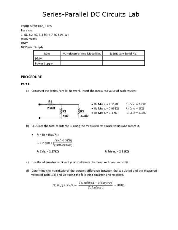
a) Construct the Series-Parallel Network. Insert the measured value of each resistor.
R1 Meas. = . KΩ
R2 Meas. = . KΩ
R3 Meas. = . KΩ
R1 Cal . = . KΩ
R2 Cal . = KΩ
R3 Cal . = . KΩ
b) Calculate the total resistance Rt using the measured resistance values and record it.
Rt = R1 + (R2//R3)
Rt = . KΩ +
Rt Calc. = .
�Ω∗ . KΩ
�Ω+ . �Ω
)
KΩ
Rt Meas. = 2.91KΩ
c) Use the ohmmeter section of your multimeter to measure RT and record it.
d) Determine the magnitude of the percent difference between the calculated and the measured
values of parts 1(b) and 1(c) using the following equation and recorded.
% �
=|
−�
|∗
%
�=|
% �
.
�Ω− .
.
�Ω
�Ω
Rt (Calculated)
.
|∗
%
% Difference = 2.02%
Rt (Measured)
KΩ
.
% Difference
KΩ
2.02%
e) If 12V were applied, as shown in the Fig. Calculate the Currents Is, I 1, I2 and I3 using the measured
resistor values and record it.
Is = It = I
Vt = It ∗ Rt
V = It ∗ . KΩ
� =
.
�
KΩ
It Calc. = 4.04mA
It Meas. = 4.09mA
f)
V =� ∗�
V = . mA ∗ . KΩ
V1 Calc.. = 8.89V
V1 Meas. = 8.85V
V2 Calc. = V3 = 3.11V
V2 Meas. = 3.15V
V
I2 Calc. = 3.11mA
I2 Meas. = 3.14mA
�
I3 Calc. = 0.94mA
I3 Meas. = 0.95mA
V = V = Vt − V
V = V− . V
I =
I =
V
R
.
V
I =R
I =
.
KΩ
. �Ω
Apply 12 V, measure the currents I1, I2, I3 and Is using the milliammeter section of your multimeter,
and record it. Be sure the meter is in series with the resistor through which the current is to be
measured. Calculate the magnitude of the percent difference between calculated and measured
values using the previews equation and enter in Table.
% �
� =|
.
��− .
��
� =|
.
��
.
��
.
��
.
��
|∗
% �
� =|
.
��− .
��
.
��− .
��
% �
� =|
.
��− .
��
% �
|∗
|∗
|∗
%
% Difference = 1.23%
%
% Difference = 0.96%
%
%
% Difference = 1.23%
% Difference = 1.06%
�The Currents Is and I1 are the same, because on a Series Circuit the Current is the same. In the
circuit R1 is in Series with the Voltage Source, so the law is applied.
Is
Calculated
4.04mA
Measured
4.09mA
% Difference
1.23%
I1
4.04mA
4.09mA
1.23%
I2
3.11mA
3.14mA
0.96%
I3
0.94mA
0.95mA
1.06%
g) Using the results of part 1(e), calculate the voltages V1, V2 and V3 usind measured resistor values
and record them.
V =� ∗�
V = . mA ∗ . KΩ
V1 Calc. = 8.89V
V = V = Vt − V
V = V− . V
V2 Calc. = 3.11V
h) Measure the voltages V1, V2 and V3, determine the magniuide of the percent difference between
the calculated and measured values, and record the results in the table.
% �
% �
% �
� =|
� =|
� =|
.
�− .
�
.
�− .
�
.
�− .
�
.
�
.
�
.
�
|∗
%
|∗
%
|∗
% Difference = 0.45%
%
% Difference = 0.32%
% Difference = 0.32%
V1
Calculated
8.89V
Measured
8.85V
% Difference
0.45%
V2
3.11V
3.10V
0.32%
V3
3.11V
3.10V
0.32%
On a Parallel Ccircuit the Voltage is the same. In the circuit, R2 is in pparallel with R3. So the Voltage
is the same in both Resistors.
�i)
Refering to the table. Does E = V1 + V2, as required by Kirchhoff Voltage law?
Yes, the law is applied at those Voltages.
PART 2:
a) Construct the Serries-Parallel Network. Insert the measured value of each Resistor.
R1 Meas. = . KΩ
R2 Meas. = . KΩ
R3 Meas. = . KΩ
R1 Cal . = . KΩ
R2 Cal . = KΩ
R3 Cal . = . KΩ
b) Calculate the total resistance Rt using the measured resistor values and insert in Table.
Rt = R1 // (R2 + R3)
Rt =
. �Ω∗ . KΩ
. �Ω+ . �Ω
Rt = 1.46KΩ
Rt Meas. = 1.43KΩ
c) Use the ohmmeter section of your multimeter to measure the total Resistance RT and record it in
the table.
� =|
% �
.
Rt (Calculated)
.
KΩ
�Ω− .
.
�Ω
�Ω
|∗
%
Rt (Measured)
.
KΩ
% Difference = 0.45%
% Difference
2.05%
d) If 12V were applied to the Network, as shown in the Fig. Calculate the Currents Is, I 1, I2 and I3 using
the measured Resistor values and insert in Table.
�
Is = It
It =
It =
Vt
Rt
.
V
KΩ
It Calc. = 8.22mA
It Meas. = 8.3mA
I =
I =
V
R
V1 = E
V
. KΩ
I1 Calc. = 5.45mA
I = I = It − I
� =� = .
I2 Calc. = 2.76mA
I1 Meas. = 5.57mA
�− .
�
I2 Meas. = 2.83mA
e) Apply 12 V, measure the currents Is, I1, I2 and I3. Calculate the magnitude of the percent difference
between calculated and measured values for each Current and record them in Table.
% �
% �
% �
% �
� =|
.
��− . ��
.
��−. .
��
� =|
.
��− .
��
.
��− .
��
� =|
� =|
.
��
.
��
.
��
.
��
|∗
|∗
|∗
|∗
%
%
%
%
% Difference = 0.97%
% Difference = 2.20%
% Difference = 2.54%
% Difference = 2.54%
R2 an R3 are in Series, so the Current is the same in those Resistors by law.
�f)
Refering to the Fig. Does Is = I1 + I2, as e ui ed y Ki hhoff s Cu e t Law?
Yes, In the Circuit, R1 is in Parallel with R2. At the same time R2 is in Series with R3, Therefore I2 is
the same as I3. Then, by definition, the sum of I2 + I1 is the Total Current of the Circuit.
Calculated
Measured
% Difference
Is
8.22mA
8.3mA
0.97%
I1
5.45mA
5.57mA
2.20%
I2
2.76mA
2.83mA
2.54%
I3
2.76mA
2.83mA
2.54%
g) Using the results of oart 2(d) and measured Resistor values, calculate the Voltages V 1, V2 and V3,
and record in Table.
V1 = Vt = E = 12V
� = � ∗�
� = .
� ∗ . �Ω
V2 Calc. = 9.11V
V2 Meas. = 9.23V
V =I ∗R
V = .
V3 = 2.76V
mA ∗ KΩ
V3 Meas. = 2.81V
h) Measure the Voltages V1, V2 and V3 and record them in Table.
Calcule the magnitude of the percent difference between the calculated and the values for each
Voltage and in sert in Table.
% �
% �
% �
� =|
� =|
� =|
�−
.
�
.
�− .
�
.
�− .
�
�
.
�
.
�
|∗
|∗
%
% Difference = 0.33%
%
% Difference = 1.81%
|∗
%
% Difference = 1.32%
Calculated
Measured
% Difference
V1
12V
12.04V
0.33%
V2
9.11V
9.23V
1.32%
V3
2.76V
2.81V
1.81%
�How are the Voltages E, V1 and the sum of V2 and V3 related? Use Table to detrermine the sum of
V2 and V3.
In the circuit R1 is in parallel with the Voltage Source, so by law in Parallel the Voltage is the same.
Then E = V1. Also R2 and R3 are in Series. By definition, the sum of the Voltages are equal to the
total Voltage, so V2 + V3 = Vt = E = V1
PART 3:
a) Construct the Serries-Parallel Network and Insert the measured value of each Resistor.
R1 Meas. =
R2 Meas. =
R3 Meas. =
R4 Meas =
. KΩ
. KΩ‘3
. KΩ
. KΩ
R1 Cal
R2 Cal
R3 Cal
R4 Cal
.=
.=
.=
.=
. KΩ
. KΩ
. KΩ
KΩ
b) How the total Voltage across the two Series elements R1 and R2 elated to the applies Voltage E ?
Why?
Resistors R1 and R2 ar in series, so the Voltage in each Resistor is different. However, the
equivalent Resistor formed by the sum pof R1 and R2 is in Parallel with The Voltage Source. It
means, the Voltage of the two combinated Resistors V1 + V2 = E.
� = � + � // � + �
� =
. �Ω + . KΩ // . KΩ + KΩ
� =
�Ω // . KΩ
KΩ∗ . KΩ
Rt =
�Ω+ . KΩ
Rt Meas. = .
Rt Calc. = 2.29KΩ
�
� =�
It =
.
V
�Ω
It Calc. = 6.99mA
� = � +�
� =�
KΩ
It Meas. = 7.09mA
= � +�
=
� =�
� =� +�
�
� � +� =�
� = . �Ω + . �Ω = �Ω
�
� =
Then � = �
� = ��
� � +� =�
� = . �Ω + �Ω = . �Ω
�
�Ω
Then � =
�
�
� =� =� =
�
� =
�
� = ���
. �Ω
� =� =� =
�
How is the total Voltage across the two Series elements R3 and R4 related to the applied Voltage
E ? Why?
As the previous tworesistors, R3 and R4 are in Series, so the Voltage in each Resistor is different.
By definition, the sum of the two Voltages V3 + V4 = E
c) Using the conclusions of part 3(b), calculate the Voltages V2 and V4, using the Coltage Divider
Rule and measured Resistor values in Table.
�� = ��
� =�
�
�
�
�
� = . �Ω
V1 Calc. = 6.6V
� =�
�
�
V2 Calc.= 9.4V
�
�
�
� = �Ω
V4 Calc. = 5V
V1 Meas. = 6.64V
V2 Meas. = 9.36V
�
V3 Calc. = 11V
� =�
�Ω
�
� = . �Ω
�Ω
�
� = . �Ω
� =�
�
.
. �Ω
V3 Meas. = 11.04V
�
. �Ω
V4 Meas. = 5V
�d) Measure the Voltages V2 and V4 and recor them in Table.
Calculate the magnitude of the percebt difference between calculated and measured values and
insert them in Table.
� =|
% �
. �− .
�
�
. �
% �
� =|
. �− .
% �
� =|
�− �
. �
�−
� =|
% �
�
f)
�
=
|∗
|∗
�
|∗
%
% Difference = 0.61%
%
% Difference = 0.36%
%
%
% Difference = 0.43%
% Difference = 0.0%
Calculated
Measured
% Difference
V2
9.4V
9.36V
0.43%
V4
Vab
5V
4.4V
5V
4.36V
0%
0.91%
Is
6.99mA
7.09mA
1.43%
e) Usi g the esults of pa t
it in Table.
.
�
|∗
, al ulate the Voltage Va , usi g Ki hhoff s Voltage Law a d e o d
�− . �
Vab Calc. = 4.4V
Measure the Voltage Vab and determine the magnitude of the percent difference between the
calculated and measured values and recor them in Table.
% �
�
=|
. �− .
. �
�
|∗
%
% Difference = 0.91%
g) Is the Voltage Vab also equal to V3 – V1. Why?
There are equal because the junctions are just right after the Resistor R 1 and R3 respectively. By
definition, the Voltage of V1=Va, and also V3 = Vb
h) Calculate the current Is, using any method you prefer. Use measured Resistor values and record
in Table.
� =� =
�
�
=
.
�
�Ω
Is = It = 6.99mA
�i)
Measure the Current Is and calculate the magnitude of porcent difference between calculated
and measured values and recor them both in Table.
�
� =�
It =
.
V
�Ω
It Calc. = 6.99mA
It Meas. = 7.09mA
PART 4:
a) Construct the Serries-Parallel Network and Insert the measured value of each Resistor.
R1 Meas. =
R2 Meas. =
R3 Meas. =
R4 Meas =
. KΩ
. KΩ
. KΩ
3.26 KΩ
R1 Cal
R2 Cal
R3 Cal
R4 Cal
.=
.=
.=
.=
. KΩ
KΩ
. KΩ
. KΩ
b) Calculate the Voltage V4 using the measured Resistor values and insert the result in Table.
� = � + � // � + �
�
� +�
‘ = KΩ
=�
Then � = � + � //�
�
� //�
� =
� ∗�
� +�
=�
Then � = � + �
Rt Calc. = . KΩ
.
� =
�Ω
Rd = 0.89KΩ
KΩ
Rt Meas. = .
Ω
�
� = � = � = � = � +� +�
� =
�
�
Is Cal. = 6.47mA
� = � ∗�
� = .
Is Meas. = 6.6mA
� ∗ . �Ω
V1 Calc. = 14.23V
� = � −� = �
� =
�−
V2 Calc. = 5.77V
.
�
� =� +� = .
�
�
� = . �Ω
V4 Cal. = 2.38V
.
V2 Meas. = 5.81V
�
Vc = 5.77V
� =�
V1 Meas. = 14.19V
V
K�Ω
V4 Meas. = 2.4V
c) Measure the Voltage V4 and calculate the magnitude of the percent difference between
calculated and measured values and record in Table.
% �
� =|
.
�− . �
.
�
|∗
%
% Difference = 0.84%
d) Measure the Current Is and calculate the total input Resistance from � =
Calculated
Measured
% Difference
V4
2.38V
2.4V
0.84%
Is
6.47Ma
6.6mA
2.01%
Rt
3.09kΩ
.
KΩ
�
�
and record in Table.
1.94%
e) Disconnect the Power Supply and measure Rt using the Ohmmeter section of DMM. Then
calculate the magnitude of the percent difference between the calculated and measured values.
Record both results in Table.
% �
� =|
.
�Ω− .
.
�Ω
�Ω
|∗
%
% Difference = 1.94%
�EXERCISES:
1. For the Series-Parallel Network determine V1, R1 and R2, using the information provided. Show all
work! Assume Rint = 0Ω fo all ete s.
=� +�
� = � ∗�
For the first part R1//R2. Then I1//I2
Call R1//R2 = Ra
�+
�=
�=�
Now is a Series Circuit. So Ia = Is = 3mA
� ∗�
� =�
+�
� =�
�
� =�
� = �.
� = �.
�
�= .
�
�
�
�
�= .
�Ω
�Ω
��
�
��
�
R1 = . KΩ
R2 = . KΩ
�
 Luis Roman