Adv. Space Res. Vol. 12, No. 1, pp. (l)109—(l)112, 1992
Printed inGreat Britain. All rights reserved.
0273-1177/92 $15.00
Copyright @ 1991 COSPAR
CONFOCAL MICROSCOPY IN
MICROGRAVITY RESEARCH
A. P. H. Goede,** G. J. Brakenhoff,* C. L. Woldringh,*
J. W. G. Aalders,*** J~P. Imhof,~’P. van Kralingen,**
W. A. Mels,** P. Schreinemakers** and A. Zegers**
* Universisy of Amsterdam, Departmentof Cell Biology, Section Molecular
Cytology, Amsterdam, The Netherlands
** SRON, Laboratory for Space Research, 3584 CA Utrecht, The Netherlands
*** SRON, Laboratory for Space Research, 9700 AV Groningen, The
Netherlands
ABSTRACT
We have studied the application and the feasibility of confocal scanning laser microscopy (CSLM) in microgravity research. Its superior spatial resolution and 3D imaging capabilities and its use of light as a probe,
render this instrument ideally suited for the study of living biological material on a (sub-)cellular level. In
this paper a number of pertinent biological microgravity experiments is listed, concentrating on the direct
observation of developing cells and cellular structures under microgravity condition. A conceptual instrument design is also presented, aimed at sounding rocket application followed by Biorack/Biolab application
at a later stage.
INTRODUCTION
The confocal scanning laser microscope (CSLM) is a light microscope with inherently higher (sub-micron)
resolution compared with a conventional light microscope. In particular, the higher axial resolution allows
optical sectioning of the object and the build-up of its 3D image to take place. The higher resolution is
brought about by limiting the field of view to a point imaged onto a point, which is subsequently scanned
across the object. The serial signal thus obtained is directly suited for computer processing. The principle
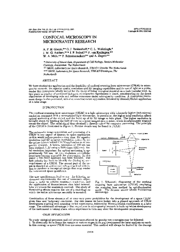
of the CSLM is illustrated in Figure 1. Further details may be found in /1,2,3/.
The automatic image acquisition and processing of a
CSLM is one aspect of interest to space application
as this would reduce precious crew time. Its superior
resolution and 3D imaging capabilities, naturally are
the prime drivers behind CSLM application to microgravity research. A lateral resolution of 196 nm has
been realised /1,2/ using a HeNe laser (633 nm). Axial resolution important for optical sectioning is approximately 750 nm. At this resolution sub-cellular
structures become amenable for observation. In this
paper a two-lined approach has been followed. The
first priority has been to identify the (biologist) user
requirement of a CSLM. The second part of the paper is directed at system and sub-system level with an
aim to produce a conceptual design that may render
the instrument space qualifiable.
The user specifications lead to a.o. the following instrument requirements; the use of immersion objectives in order to achieve maximum resolution, and
the application of fiuorochromes that label intercellular structures for maximum contrast. The study of
threshold-g effects requires the use of a centrifuge on
which the entire microscope assembly is mounted.
b
0
~OntroL
jeotpi~ne
Iensscanner
S
objeeti~e
illu~i
1nation
\
dictiroic
U
laser
mirror
computer
-video
d~t~c~or
Screen
detector
Fig. 1. Schematic diagramme of the confocal
scanning laser microscope (CSLM) employing
the scanning lens method in epi-illumination
mode. The dichroic mirror allows fluorescence
microscopy.
Combination of these elements all at once may prove prohibitive for the development of a space CSLM,
given time and budgetary constraint. For this reason we have looked into a phased approach of CSLM
development starting with sounding rocket experiments, followed by Biorack/Biolab experiments at a later
stage. The additional advantage is that experience in microgravity research is built up whilst development
of the instrument is taking place, which experience in turn may steer the development programme.
�(1)110
A.P.H.Goedeetal.
caused to the sample by the fixation, freezing and storage process.
2. The second strategy is to observe single cells in vivo during their jz-g development. This strategy is
ideally suited for CSLM application in space and is subject of this paper.
The phenomena that can be expected to be influenced under microgravity conditions include maintenance
of cell shape, localization and partitioning of nucleus and other organelles, and chromatin motion. In all
these cases the assembly of the cytoskeleton plays a principal role. The best way to study these processes is
by three-dimensional in vivo time-lapse imaging of a single cell in which various macromolecules or cellular
compartments have been labeled by fluorochromes or indicator dyes. Because of its inherent high resolution
and its ability to optical sectioning, the CSLM is suitable both for a 3D-exploration of whole cells as well as
for a high-precision localization of labeled substructures. The CSLM is also the most versatile instrument
for switching quickly from low magnification (cell shape inspection) to high magnification (examination of
labeled components).
Only recently reports have been published in which the CSLM has been applied to living cells. In Table 1 a selection of possible new in vivo objects for CSLM study under microgravity condition is presented/4,5,6,7,8,9/. These are derived from recent studies in which conventional fluorescence microscopy or
video microscopy has been applied to living objects. No attempt has been made to present an exhaustive
list of specimens suitable for live observation. Instead, some general specimen requirements are discussed
below.
TABLE 1
Possible new specimen for
vo observation of Living animaL cells
(md. ftuorochromes, microscope used and rate of change)
Object
pretreatment
Fluorochrome
m excitation
Size
ceLL/substructure
1. Susan fibrobtast
microinjected
Xrhodamine-tubutine
520 nfl
25 ml dime.
microtubuti*)
Lens
(final magnific.)
Rate of change
(time intervaL)
lOOx planapo
3.5 mmvmin
dig. video micr.
(60 sec)
(2500 x)
2. PtK2 cells on coverC2CF-tabeted tubuLine 25 ml diam.
lOOx neofluor Phase 3 0.5 sail/sec
slip microinjected
480 ns
chr~somespindle (4000 x)
(5 mm)
3. CV-1 ccl Is (epitheDiOC
6(3)
400 ml diem.
lOOx neofluar NA 1.2
1.15 maiVsec
List) on coverslip
(Lipophilication)
ER-tubuLes
(5000 a)
(2 sin)
4. One-cell mouse ee*ryo Hoechst 33342
10i~ndiam.chromatin 40 a Oiyepus
1 flm/min
vital stained
370 ,si~
condensation
(600 a)
(60 mm)
5. Hippocanpal brain
Fura-2
100x500 ~m whoLe
lOxHikon UVF
slice microinjected
340&380 (ratio method) ceLL Ca-accua.il.
(water i,mniers. 50 x)
(5-10 sec)
6. Drosophila-blastoqier
rhodamine histones
500 ne diem.
60x/NA 1.4
0.5 Jim/sec (23°C)
microinjected
~negafilter
chromosome
OLynpus-oit isis.
(25 sec)
condensation
(1600 a)
*
Reference
Sansiiak & Borisy
1988
/4/
Hitchison
1989
/5/
Lee & Chen
1988
/6/
Debey et at.
1989
/7/
Regehr et aL.
1989
/8/
Hiraoka et at.
1989
/9/
average life time of microtubules in fibroblast is 10 sin.
With regard to the animal cells distinction should be made between anchorage-dependent cells (like epithehal PtK2 cells or 3T3 fibroblasts), which grow while attached to a substratum (coverslip) and anchorageindependent cells (like lymphocytes and transformed cells), which are suspended in a growth medium.
Different views have been expressed as to the susceptibility of anchorage dependent cells to microgravity,
but for the moment no conclusion can be drawn. The correlation between lymphocyte proliferation, adhesion, spreading and shape as well as metabolism (lymphokine production) is the subject of present space
programmes, after the discovery of the dramatic decrease in response of lymphocyte cells to treatment with
the mitogen concanavaline A under ~i-g condition /10/. In future it will be important to extend these
studies to CSLM observations on structural changes, both on the level of cytoskeleton organization and
specific protein localization.
During recent years the mouse embryo cell has developed into an important model system for human cell
development studies. After fertilization, the embryo reaches the eight-cell stage after about 2.5 days at
which time a dramatical morphological reorganization occurs, leading to a fixed polarity along any radial
axis. This type of process may be expected to be affected under microgravity conditions.
The measurement of intracellular movements of, for example, calcium ions deserves special attention. For
many cellular processes, the changes in intracellular ion concentrations are relatively slow, in the range
of minutes. Recently, new dual emission dyes have been developed, with which intracellular ions can be
determined (ratio method). With these dyes the emitted light intensities can be measured simultaneously
at two wavelengths, making use of a beam splitter and two detectors, a set-up well applicable to confocal
microscopy.
�Confocal Microscopy m Microgravity Research
(1)111
can be observed by automated scanning in sounding rockets. Processes in animal cells can probably only
be observed in a crew-tended space laboratory.
(2) It seems important to be able to observe the same cell before and after the transition from 1- to ~
especially in the case of subcellular structures. This necessitates the mounting of the CSLM on a centrifuge
like the NIZEMI. Clinostat systems equipped with a CSLM could serve as pilot experiment.
(3) The most difficult problem is the storage of living cells for periods over 24 h. Time consuming experience
has to be ~ained in understanding how reproducible the individual cells selected for observation are, what
their physiological condition is during storage and after reactivation, and how they would survive the
damaging effects of fluorochrome labeling and illumination. The clinostat may provide a way to build up
such experience.
INSTRUMENT DEVELOPMENT
The recommended phased approach for CSLM space application, starting with sounding rocket (S/R)
experiments, followed by Biorack/Biolab experiments at a later stage, has narrowed down the conceptual
design to S/R application in the present paper.
As a result of a conceptual design study the epi-illuminated scanning lens principle has proved most appropriate for S/R application. Its simplicity of design (one lens only) lends itself ideally to miniaturisation and
maintenance of tolerances. The on-axis confocal sampling principle has inherently good optical properties,
i.e. near-ideal confocal imaging, minimum aberration, high transmission efficiency and large image fields
depending on scan excursion. Scan speeds and thus image acquisition times in general tend to be lower
than in off-axis approaches. This disadvantage is mitigated by better signal collection conditions.
Sounding rockets offer 6 to 7 minutes of microgravity condition. This time r~ sets an upper limit to
the characteristic time Tchar of the experiments that are suitable for S/R application. The characteristic
experiment time is constrained from below by the CSLM scan time Tscan. Practical limits to the (mechanical)
scan frequency lead to acquisition times for 2D and 3D images respectively of 2 sec and 30 sec. Thus, in
the selection of experiments suitable for S/R application, the following time ordering applies:
T
5~50<<Tchar <<T~zg
With Tscan = 30 sec and T~,g= 6 mm this ordering can only marginally be fulfilled leading to characteristic
experiment times in the order of 1 minute.
154
Fig. 2. System design CSLM
__________
6
5
The CSLM system design is given in Figure 2. It shows the assembly of the light source (1), detector (2),
dichroic mirror (3), relay mirror (4), fibre optics (5), sample holder (7), lens scanner system (8), guiding
rails (9), electrical feedthrough (10) and the high voltage power supply (11). The entire system is enclosed
in a temperature controlled vacuum tight enclosure (6) of external dimensions 175 x 154 x 125 mm. Total
mass of a CSLM system is approximately 4.5 kg. This compact design allows the fitting of an entire CSLM
module through the access hatch of a sounding rocket module with only low voltage electrical connections
to make. The advantage of this concept clearly is that the (biological) experiment can be prepared on the
ground under controlled laboratory conditions before installation in the sounding rocket. It also permits a
late access scenario required for some biological experiments.
The lens scanning system (8) is a patented design by Dr. G.J. Brakenhoff. The scanning lens is supported
by three rigid supporting rods linked by flexing pivots to a baseplate to allow x-y freedom of scan. The
z-scan movement is accomplished by a slotted link mechanism machined into the baseplate which is levered
through linking wires. Displacements in x-y-z direction is effected by independent actuators (linear motors).
�A.P.H.GoedeetaL
(1)112
Stresses are shown to be acceptable during scan, but exceed the yield stress during 25g-acceleration at
lift-off and ground impact. To limit the displacement of the spring elements during 25g-acceleration the
scanning mechanism needs to be locked during launch and reentry. A locking device has been incorporated
in the form of an end stop to the x-y-z-scan.
S
The mechanical tolerances of the optical components are primarily governed by the relative position accuracy of the source and the detector pinhole with respect to the dicbroic mirror. In this design these
components are rigidly linked into one machined block. The laser light output is guided by fibre optics
permanently fixed to the laser. The fibre exit, serving as entrance pinhole, is connected to the dichroic
mirror block via a plug-in connector. This allows exchange of pinhole size, or dichroic and the addition of
grey filters to suit specific experimental conditions.
The compact design of the CSLM system offers the possibility of accommodation of two to four CSLM
modules in the sounding rocket space envelope. This concept offers the following advantages:
— it allows dedicated experiments to be carried out simultaneously during one mission. For instance, one
CSLM may be equipped with immersion oil whilst others are not.
— the accelerations introduced by the CSLM scanning mechanism may be synchronised in anti-phase such
as to preserve the microgravity condition.
The following electro-optical components are specified
— diode pumped frequency doubled Nd-YAG laser, power 5 mW, wavelength 532 nm, linear polarized.
— photomultiphier, S20 photocathode, system noise < 1 photon/pixel, current integration/digitisation into
8 bit word, max. light level> 10e4 detected photons/pixel, detector output signal controlled by detector
gain and/or detector pinhole size.
— data acquisition over quasi-linear part of sinusoidal scan in both directions of the x-scan, y-scan linear.
sawtooth, z-scan step-wise, pixel sampling equidistant in time, integration time per pixel 28.8 /4sec.
The total number of pixels for one 3D image scan is 256 x 256 x 16 = 1 Mpixel. This corresponds to 8.4
Mbit for 8 bit pixel resolution. The corresponding data rate for a 3D image collection time of 60 sec is then
about 140 kbit/sec. The data frames are downlinked without any preprocessing in the spacecraft to take
place. Each frame consists ofmax. 512 pixel words of 8 bit each (two line scans x-direction). Housekeeping
data are included into each frame. This will lead to an increase of several bytes/sec, which is negligible.
Frame transfer takes place every 25 msec (40 Hz).
The total electrical power budget amounts to 4.5 W exclusive laser power supply. The commercially
available laser power supply requires 30 W, but this may be brought down to 10 W. At a power convertor
efficiency of 60% the total primary power then becomes 25 W.
CONCLUSION
Space confocal microscopy should be primarily directed at the study of living specimen. Suitable objects
have been identified. Most critical problem will be the storage of living cells. A stepped approach toward
CSLM application in Biolab/Biorack should include: agroundbased programme for selection and characterisation of suitable specimens, CSLM study of selected objects on earth in a clinostat, followed by sounding
rocket tests. Sounding rockets will provide both an instrument test as well as valuable preliminary data on
the 3D organization of selected specimen under j~-g.A conceptual CSLM design for S/R application has
been presented.
ACKNOWLEDGEMENT
This work was carried out under ESTEC contract 7336/87/NL/PB(SC)
-
CCN3 as part of the Life Science
Facility Technology Study. Valuable comments by Drs. P. Schiller and P. Kern are much appreciated.
REFERENCES
1.
2.
3.
4.
5.
6.
7.
-
G.J. Brakenhoff ci ci., Scanning Microscopy 2, Nr.1 p.33—40 (1988).
G.J. Brakenhoff ci al., Journal of Microscopy 1, p. 219—232 (1979).
G.S. Kino, T.R. Corle, Phys. Today, p.55 Sept. (1989).
P.J. Sammak, and G.G. Borisy, Nature 332, p. 724—726 (1988).
T.J. Mitchison, J. Cell Biology 109, p. 637—652 (1989).
C. Lee, and L.B. Chen, Cell 54, p. 37—46 (1988).
P. Debey, J.-P. Renard, M. Copey-Moisan, J. Monnot, and M. Geze, Exptl. Cell Res. 183, p.413—433
(1989).
8. W.G. Regehr, .J.A. Connor, and D.W. Tank, Nature 341, p. 533—536 (1989).
9. Y. Hiraoka, J.S. Minden, J.R. Swedlow, J.W. Sedat, and D.A. Agard, Nature 342, p. 293—296 (1989).
�
 Conrad Woldringh