1514
zyxwvutsrqpo
zyxwv
zyxwvutsrqponmlkjihgfe
IEEE JOURNAL OF SOLID-STATE CIRCUITS, VOL. 29. NO. 12. DECEMBER 1994
zyxwvu
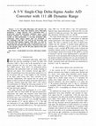
A Stereo Audio Sigma-Delta AD-Converter
Tapani Ritoniemi, Eero Pajarre. Seppo Ingalsuo, Tim0 Husu, Ville Eerola, Student Member, IEEE, and Tapio Saramiiki
AA
Abstract- A stereo sigma-delta AID-converter for audio applications is presented. In this converter, two identical cascaded
fourth-order sigma-delta modulators and a sophisticated multistage linear-phase FIR decimation filter with oversampling ratio
of 64 are implemented on the same die. The analog part is designed to operate at a low voltage with a low power consumption.
Techniques to achieve simultaneously a high performance and a
low power consumption are discussed in details. The minimum
stopband attenuation of the decimator is more than 120 dB and
the passband ripple of the overall converter is less than 0.0003 dB.
The first decimation stage is a special tapped comb filter, whereas
the remaining stages are realized without general multipliers by
simultaneously implementing all the filter coefficients by using
special bit-serial networks. For the integrated overall stereo
converter, the power consumption and the signal-to-noise ratio
are 180 mW and 97 dB (85 mW and 95 dB) for a 5 V (3 V)
power supply. The circuit die area is only 4.7 mm x 5.5 mm
using a 1.2 p m double-poly BiCMOS process.
Dout
I. INTRODUCTION
T
HE ADCONVERTERS, based on the use of oversampling and sigma-delta (SD) modulation followed by the
decimation process, are currently the most popular converters for audio applications. These converters have significant
advantages over conventional AD-converters, such as modest
circuit accuracy and matching requirements making them easily realizable as a VLSI circuit. In addition, the requirements
for the external antialiasing filter are highly relaxed by the
internal decimation process following the modulation.
Despite the very attractive features of SD A/D-converters,
there are some remaining fundamental problems. One of the
major problems is that the analog part has to operate at a
high sampling rate because of the need for oversampling.
The oversampling ratio (OSR) is a function of the required
signal-to-noise ratio (SNR), the order of the modulator, the
modulator topology, and the number of quantized bits used in
the modulation. Distortion-free one bit quantization is easy to
implement compared to a multibit quantization, but it requires
either a higher-order modulator structure or a higher OSR. The
existing modulators use either feedforward (FF) or multiple
feedback (MFB) structures shown in Fig. 1, [ 11-[4] or cascades
of these blocks [ 5 ] . Extreme cases are MASH structures [6],
[7] using first-order building blocks. Given the desired SNR,
the first problem is select those OSR’s and the modulator
types that theoretically fullfil the criteria. The selection among
these candidates depends on such factors as the circuit noise
generated by the practical integration of the modulator, the
required integrator dc gain of the operational transconductance
amplifier (OTA), the sampling rate of the modulator, and the
Fig. I . Block diagrams for SD modulators. (a) Feedforward modulator; (b)
multiple feedback modulator.
complexity of the decimator filter. These factors affect the
silicon area of the overall converter, the practically achievable
SNR, and the power consumption.
The second problem+specially for high-resolution converters-is the efficient small area integration of the decimator filter
and the need of having it on the same die as the modulator. The
interference between analog and digital part has been a limiting
factor in many previous mixed signal circuits. Therefore, the
existing high-performance SD ADconverters use separate
dies for the digital and the analog parts [ 3 ] . Another goal
in audio applications is to synthesize the decimator in such a
way that it is a linear-phase finite impulse response (FIR) filter
and both the decimator performance (filter selectivity) and the
VLSI realizability (circuit area, power consumption, speed) are
simultaneosly optimized. In most existing implementations,
the filter has been implemented using several FIR filter stages
with the first stage being normally a cascade of comb filters
[ 2 ] , [6], [8]-[10], [ l 11. For the remaining stages, most of the
silicon area is usually occupied by the multiplier elements. One
approach to avoid the use of general multipliers is to synthesize
the filter stages by using a tapped cascaded inteconnection of
identical multiplier-free subfilters [9], [ 101, [ 111. The main
drawback of this approach is that the required number of
memory elements is approximately 30 to 40% higher than that
required by conventional direct-form FIR filters.
zyxwvutsrqp
Manuscript received June 13, 1994; revised August 29, 1994.
The authors are with VLSI Solution Ov, Kanslerinkatu 6, Tamuere. Finland.
IEEE Log Number 9406265.
zyxwvuts
zyxwvuts
0018-9200/94$04.00 0 1994 IEEE
zyxwvutsrqponmlkjih
zyxwvutsrqponmlkjihgf
zyxwvutsrqponmlkj
151.5
RITONIEMI er a/.: A STEREO AUDIO SIGMA-DELTA A/D-CONVERTER
This paper presents an integrated stereo SD A/D-converter
for audio applications that addresses the conflicting requirements of a small silicon area, a low power supply, a low
voltage, and a high SNR. The desired performance figures have
been selected to be 150 mW, 5 V, and 100 dB, respectively. In
this converter, an extra effort has been devoted to integrating
the decimation filter on the same die in such a way that its
interference to the analog part is minimized. Even though
the desired overall performance was not achieved in the
first silicon, the performance of the prototypes indicates the
potential of reaching the goals after some fabrication rounds
and optimization of the circuit layout. The circuit die area for
the overall converter is only 4.7 mm x 5.5 mm using a 1.2
prn double-poly BiCMOS process.
This paper is organized as follows. In Section 11, it is
shown that a proper OSR is 64 and a cascaded fourth-order
modulator consisting two cascaded second-order FF blocks is
from the practical implementation point of view the best one
among those altematives theoretically achieving the desired
SNR. This modultor uses one noise-shaping zero-pair in the
baseband [12], improving the SNR by approximately 10 dB.
Both the signal and noise transfer functions are considered
in details. Section 111 considers practical implementatation
aspects of the proposed modulator such as the voltage scaling,
performance limitations, and the design of suitable OTA’s for
implementation, whereas Section IV shows how the interference caused by the decimator filter to the modulator section
can be made negligible. Finally, Section V is devoted to
the decimator design. Compared to earlier linear-phase FIR
filter designs, the proposed decimator is improved in two
ways. First, a special tapped comb filter introduced in [13]
is used as the first stage. Compared to conventional comb
filters [9], [ 141-[ 171, this filter uses additional interconnections
reducing the number of feedback and feedforward term as
well as the number of bits required in intemal calculations,
resulting in a significant reduction in the silicon area. For
the remaining filter stages, the number memory elements is
made almost the minimum by implementing accurate filter
coefficients without general multiplier elements by using a
special bit-serial network that generates all the coefficient
values with a small amount of add and shift operations. Finally,
Section VI gives measurements illustrating the performance of
the overall integrated chip.
Ci
Vin
zyxwvutsrq
zyxwvuts
zyxwvuts
zyxwvu
Fig. 2. Configuration of the integrator.
VALUES OF’@
FOR
TABLE I
DIFFERENT
MODULATOR
STRUCTVRES
Modulator topology
Fourth-order cascaded with
c. I c, h i 1Knm.*
0.50
1.25
I
@ in dB
2.50
8.0
~
second-order F F blorks
Fourth-order F F
0.45
1.67
3.66
11.2
Fifth-orderh FF
0.43
2.00
4.61
13.2
Fourth-order cascaded with
0.25
1.25
5.00
14.0
second-order MFB hlorks
Fourth-order MFB
0.17
1.67
10.00 20.0
Fifth-order MFB
0.14
2.00
14.08 23.0
11. FOURTH-ORDER
CASCADEDMODULATOR
For all the above alternatives, the circuit noise caused
by the practical integration of the modulator is higher than
the theoretical quantization noise determined according to
the block diagram. Therefore, it is advisable to select the
structure for which the circuit noise level at the modulator
output is the lowest in the baseband. To achieve this, we
can concentrate on the amount of the circuit noise caused
by the first integrator to the modulator output. Because of
noise shaping, the contribution of the other integrator stages to
the output noise is considerably smaller. The transfer function
for the noise generated by the first integrator to the output
is the same as for the signal passing through the modulator.
Therefore, it is practically unity in the baseband and all that
remains is to minimize the gain by which the noise generated
by the OTA of the first integrator is amplified. The schematic
of the first integrator is depicted in Fig. 2. The desired gain
is approximately given by
The OSR has been selected to be 64 for two main reasons. First, the resulting maximum sampling frequency of the
modulator for audio applications (maximum output sampling
rate of 48 kHz) is 3.072 MHz, that is within reach due
to the development of the (Bi)CMOS technology. Second,
there exist several modulator candidates for which the signalto-quantization noise in the baseband exceeds 100 dB with
modest component matching requirements. The modulator
candidates are the fourth-order MFB, the fourth-order FF [ 2 ] ,
fifth-order MFB [3], and fifth-order FF modulators as well as
fourth-order cascaded modultors using either two second-order
FF blocks or two second-order MFB blocks [5].
where Vinmax and Vref are the maximum input voltage and
the reference voltage (c$ Fig. 6), respectively. The above
formula assumes that the one-bit feedback capacitor is of the
same size as C,. Table I compares the values of 9 for the
candidate modulator structures. These values are based on
previous modulator designs and simulations [4], [ 5 ] .
From the table, it is seen that the fourth-order structure with
two second-order FF blocks has the smallest 9. Since C,
is predetermined according to the desired value of thermal
(k?’/C) noise, the smallest value of
indicates that this
zyxwv
6 = (c~/cs.)(~ef/Kn,,,)~
(1)
1516
zyxwvutsrqponmlkjihgf
zyxwvutsrqp
zyxwvutsrqpo
IEEE JOURNAL OF SOLID-STATE CIRCUITS, VOL. 29, NO. 12, DECEMBER 1994
structure requires the smallest value for C, and, therefore.
also the smallest power consumption to achieve the desired
performance [ 181.
Fig. 3 shows the modulator structure we selected. In this
structure, an additional dither signal is added before the
comparator of the first modulator block to remove idle channel
tones. The role of the scaling constant 1/C is to reduce the
input of the second modulator block to the operation range.
For determining the signal transfer function as well as the
effect of the two quantizations to the overall modulator output,
the performance of the structure of Fig. 3 is be modeled as
shown in Fig. 4, [ 191. For the input signal, the transfer function
is given by
H ( z )=
In
......____
L+J+y=pqp
Dout
Fig. 3.
Block diagram for the cascaded fourth-order modulator.
zr2
+ X1G(z)
(1 - z-’)*
In -
where
For the two quantization error sources e l and
sponding noise transfer functions are given by
e2,
the corre-
. Dout
-
2-2(1-
+ az-11
z-1)2 + az-l + X2G(z)]
*-1)2[(1
-
+
[(l- z - ~ ) ~
XlG(z)][(l -
(4)
and
(1- z - 2 y [ ( l (1 - z-2)2 az-l
+ az-11
+ X2G(z)
zyxwv
Fig. 4. Linearized model for the SD modulator of Fig. 3 with two additive
noise sources.
111. PRACTICAL
INTEGRATION
This section considers practical integration aspects of the
modulator considered in the previous section, such as the
voltage scaling, performance limitations, and the synthesis of
suitable OTA’s for implementation.
zyxwvutsrqpo
zyxwvutsrq
zyxwvutsrqp
zyxwvut
zyxwvutsrqp
Ez(z)= c
+
Here, both of the gain constants A 1 and X 2 take in the normal
operation approximately the value X1 = X2 z l / b 1 . For our
circuit, a = 0.002 and C = 4, whereas b l and b2 have easily
implementable values of 1 and 0.5, respectively. This helps
to achieve a matching which is better than 0.5% between the
modulator blocks. For 01 = 1, A 1 = Xz zz 1. The amplitude
responses of the above transfer functions are plotted in Fig.
5 in terms of fs/2, where f s is the output sampling rate
of the converter and is related to the input sampling rate
fin via f 3 = fjn/64. As seen from Fig. S(a), the signal
transfer function does not have a perfectly flat baseband, but
the amplitude distortion is equalized by the digital decimation
filter, as will be shown in Section V.
The numerators of both of the above noise transfer functions
are the same and of order 4. They generate one noise-shaping
zero-pair at dc and another zero-pair at f = O.01424(Jn/2) =
O.9111(fs/2), which is in the baseband, as is desired. Theoretically, the use of a for shifting one zero-pair improves the
SNR by 10 dB, resulting in an overall 123 dB SNR. Note
that because of oversampling by a factor of 64, the actual
noise levels at the converter output (after lowpass filtering
and decimation) are in the baseband 0 5 f 5 f,/2 18 dB
lower than those of Fig. 5(b).
Switched-Capacitor Implementation
The SD modulator of Fig. 3 has been implemented using
switched-capacitor (SC) technique. The implementation of the
first second-order modulator block is depicted in Fig. 6. The
second block is similar except for an additional zero-shifting
feedback loop. The modulator has a two-phase nonoverlapped
clocking scheme with delayed clock signals in the sampling
capacitors to reduce distortions [20].
The voltage scaling of SC-filters is a well-known way to
optimize circuit overall performance [21]. In the case of SD
modulators, the following three facts specific for SD modulators should be taken into account. First, the SD modulator
should be modeled as a linear filter before the actual scaling
can be performed as shown in Fig. 4 for our modulator.
Second, when choosing the minimum capacitor for each
integrator, the circuit noise generated by the implemented
integrators should be taken into consideration. The minimum
capacitor value of the first intergator is larger than those of
the following integrators. Third, a significant advantage of SD
modulators over conventional SC filters is that the innermost
loop gain of the modulator settles approximately to unity (221
( b l X 1 = b l X 2 z 1 in Fig. 4). The linear function does not
zyx
zyxwvutsrqponmlkjih
zyxwvutsrqpo
1517
RITONIEMI er al.: A STEREO AUDIO SIGMA-DELTA AID-CONVERTER
-'%ss-
;
zyxwvuts
101
Sellllng accuracy
I
1M
Fig. 7. Noire as a function of the linear settling accuracy of the integrators.
40,
'
'
'
1
"
//"
:
The voltage scaling of the integrated fourth-order modulator
has been accomplished in a such way that each integrator stage
has its own unity capacitors of a properly selected size. This
gives more freedom for keeping the used overall capacitor
area value as small as possible.
Performance Limitations
zyx
zyxwvutsrqponmlkj
zyxwvutsrq
zyxwvutsrqponmlkjihg
-120
l
o
o
w
'
1
.4p0+J
--
'
1 o1
1o'
The performance of SD modulators is limited by several
error and noise sources. In addition to the system-level errors
such as an inaccurate matching and a slow integrator settling,
analog noise sources reduce the achievable SNR with the
fundamental performance limiting noise source in SC implementations being the thermal ( k T / C )noise generated by
capacitors. For a sinusoidal signal, the SNR caused by this
noise is given by [23]
zyxwvutsr
Frequency[FsiP]
(b)
Fig. 5. Amplitude responses for the transfer functions of the modeled
modulator. (a) Signal transfer function H ( 3): (b) error transfer functions
E l ( z ) and E ~ ( I ) .
SNR =
where I/, is maximum sinusoidal signal peak-to-peak value,
G, is the size of the sampling capacitor, IC is the ubiquitous
Boltzmann's constant, and A4 is the OSR . For our circuit,
,'b = 4V, C, = lOpF, A4 = 64. The used differential
architecture improves the SNR by 3 dB, giving for this
architecture
S N R = 111.9 dB + 3 dB = 114.9 dB.
(7)
The effect of the settling accuracy of the integrators on
the overall output noise is shown in Fig. 7. By assuming a
0.5% gain matching between the two modulator blocks and a
integrator settling accuracy of 0.999 (including also the finite
dc gain effect), the overall performance can be estimated. The
simulated effect of the modulator gain matching on the overall
output noise is shown in Fig. 8. These results are summarized
in Table I1 which also gives the noise caused by the OTA of the
first integrator. Assuming the noise sources to be independent
the practically attainable SNR becomes approximately 107
dB. Additional noise sources are the nonlinear settling of
integrators, the interference between the analog and digital
parts, and the coupling of the power supply to the voltage
reference.
zyxwvutsrqponm
1
Fig. 6. Circuit diagram for a second-order modulator block.
depend on the voltage value before the quantization. This
property enables the realization of very selective filters with a
small capacitor value spread.
IS18
zyx
zyxwvutsrqponmlkjihgfed
IEEE JOURNAL OF SOLID-STATE CIRCUITS, VOL. 29, NO. 12. DECEMBER 1994
zyxwvutsrq
zyxwvutsrqponmlkjihg
zyxwvutsrqponmlkjihgf
I
I
0 99
1
1 02
101
Matchingaccuracy
zyxwvutsrqponm
zyxwvutsrqp
Fig. 8. Noise as a function of the modulator gain matching.
TABLE 11
NOISE CALCULATIONS
T h e r m a l noise,
C, = lOpF,A i = 64 , V, = 4V
Matching accrirary Iwtweeu Mocks < 0.5%
Integrator settling arcurary > 0.999
OTA noise aniplified by 8 dB (cf. Talde I)
1 Over&
noise
j
I
zyxwvutsrqponmlkjihgfedcbaZYXW
VOUT-
-114.9 dB
< --114.0dB
< -118.9 dB
, < -110.0 tlB
1 < -107.3 dB 1
VOUT+
lb12
(b)
Fig. 9. Circuit diagrams for folded cascode (a) and current gain (b) OTA’s.
OTA Design
Most SD modulator implementations have used SC integrators often synthesized using folded-cascode OTA’s [7],
[8] because of their fast settling. Due to the (Bi)CMOS
technology development, the required settling accuracy for the
sampling frequency of 3.072 MHz is nowadays within reach
also by several‘other amplifier types. For our circuit, fully
differential OTA structures with one-stage settling behavior
are preferred since these structures have a good high frequency
power supply and common mode rejection that is essential to
attenuate disturbances generated by the digital parts. For these
strucures, the dominant pole is generated by the capacitively
loaded output stage, whereas the other poles are located at
relatively high frequencies.
The most attractive OTA topologies are folded cascode,
current gain, and adaptive biased current gain [24], 1251. These
topologies can achieve the desired settling accuracy of 0.1%
for the linear part, a large output range ( f 2 V ) , and an over
60 dB gain. The transistor diagrams of these OTA alternatives
are depicted in Figs. 9 and 10.
The settling time constant for the integrator shown in Fig.
2 is approximately given by [26],
r=
c*+ c s + CL + (CS+ C,!
gm
x CL/G
,
(8)
Fig. 10. Circuit diagram for an adaptive biased current gain OTA.
step, the current required by the class A OTA is approximately
Ib =
2V x 28pF
z 3.5mA.
r
(9)
The current drive capability is mostly determining the power
consumption of the analog part of the converter. The estimated
power consumption of the first integrator as well as that of the
overall stereo modulator are calculated in Table I11 for the
three topologies. It is seen that the adaptively biased current
gain topology gives the lowest power consumption.
The other OTA’s in the modulator have smaller load capacitances and their power consumption is approximately half
of that of the first integrator. The stereo realization of the
modulator needs two large OTA’s and ten smaller OTA’s. The
class A OTA can operate using a slightly smaller bias current
than expected since its settling has been observed to be more
zyxwvutsrqpo
zyxwvut
For our circuit, r has been selected to be 14 ns to suppress
for half the sampling period for the sampling rate of 3.072
MHz the nonlinear part of the settling below -100 dB, that is,
e-‘Olr M lo-’ for t o = ;(1/3072000). The first integrator
has a total capacitance of 28 pF. Based on this, the required
transconductance gm can be evaluated. The settling requirement determines also the required output current. For a 2 V
zyxwvutsrqpon
zyxwvutsrqpo
zyxwvutsrqpo
zyxwvutsrqponm
RITONIEMI et al.: A STEREO AUDIO SIGMA-DELTA AID-CONVERTER
1519
TABLE 111
ESTIMATED
POWER
CONSUMPTIONS
OF OTA’s
zyxwvutsrqponmlkji
configuration
Curreut gain
linear as long as the bias current and the conductance are
determined correctly.
The schematic of the actual OTA is depicted in Fig. IO.
A P-channel input stage is used for reducing the IF-noise.
The conductance requirement has forced us to use large input
transistors making the IF-noise low. By replacing the Nchannel MOS transistors by bipolar NPN transistors, the IF
noise of the OTA can be reduced by approximately 20 dB.
The measured total power consumption for the analog part
of the stereo modulator is 102 mW. In addition to the OTA
power consumption of 20 mW for the reference voltage, this
figure includes the consumptions of comparators and clock
generators. The use of the adaptive bias has been observed to
reduce the power consumption by a factor of four.
Fig. I 1.
Circuit diagram for a sampled data common mode feedback circuit.
Activity of digital part
zyxwvutsrq
zyxwvutsrqpon
Common Mode Feedback Circuit
The fully differential OTA’s need a common mode voltage
feedback circuit keeping the sum of the outputs at the mid
point between the supply rails. The common mode circuit
always decreases the performance of the main OTA circuit,
increases the power consumption, limits the usable output
range, and increases the loading of the amplifier. The class A
common mode circuit needs to handle the peak current of the
OTA, thus resulting in a high bias current in this application.
The actual OTA operates in class A/B. The common mode
circuit is also preferred to operate in class A/B in order to get
the full benefit of the A/B class operation. The high output
impedance of the OTA’s prevents the use of resistive loading
circuit structures. From the remaining alternatives, the most
attractive structure is the sampled data common mode circuit
with the diagram is shown in Fig. 1 1 , [ 181, [27]. The increased
capacitive load of the circuit is considerably smaller than the
overall load. The structure is easy to implement as long as the
clock signals are available for the circuit. The thermal noise
generated by the capacitors of the common mode circuit is also
common mode noise. This noise contribution can be neglected
because it is attenuated very efficiently by the following OTA
or comparator stages.
IV. DIGITALCOUPLING
When integrated on the same die. the interference between
the analog and digital parts has been one of the main limiting
factors for achieving the desired SNR. The interference caused
by the digital part to the analog part can be minimized by using
three strategies. First, the fully differential implementation
cancels most of the disturbances. Second, the noisiest digital
sections are placed far way from the analog input stages. Third,
the decimator stages are implemented by using structures
that settle fast and allow the substrate to settle before the
I
1
cL
ANALOGiOCK
SWITCH OFF
CL2
OTAs are in transient
SWITCH OFF
Fig. 12. Clock signals of the converter.
analog part accepts new input samples. Since sampling can
be performed relatively fast during the silence of the digital
part [28], the interference becomes negligible. The fast settling
of the digital structures can be achieved by limiting the logic
depth. By using a synchronous two-phase clocking, a new
analog input sample is taken at the end of clock phase one,
whereas the digital part starts operation in clock phase two.
The clock signals are shown in Fig. 12. The time from the
end of clock phase one to the start of clock phase two is
long enough for sampling. In a 1.2 pm CMOS technology,
the effective sampling aperature time is only approximately 1
ns, which is the turn-off time of a MOS transistor switch. This
means that the disturbances after 1 ns from the falling edge of
clock one have no effect on the analog part. The measurements
do not indicate any disturbances from the digital part to the
analog part. There is no difference between the SNR of the
overall converters and the SNR calculated in the basedband
from 1 bit collected data when the digital part is in reset.
The routing of analog power lines and bonding has been
implemented sothat the power and signal lines do not inter-
1520
zyxwvu
zyxw
zyxwvutsrqponml
IEEE JOURNAL OF SOLID-STATE CIRCUITS, VOL. 29, NO. 12. DECEMBER 1994
Fig. 13. Circuit diagram of a band-gap voltage reference circuit
Amplitude response with SDM
0-
zyxwvutsrqpo
zyxwvutsrq
zyxwvutsrqponm
tl
-20-
-40-
-60
~
2i
0,
E-100
a
To recude the implementation costs (silicon area, power
consumption, and speed), this decimator is synthesized using
four stages. The first stage decimating by a factor of 16 is a
special tapped structure of six comb filters introduced in [ 131.
Compared to conventional comb filter structures [9], [ 141-[ 171,
the required silicon area is approximately half because the
additional interconnections reduce the number of feedback and
feedforward terms as well as the number of bits required in
internal calculations. Following this stage, an FIR filter of
length 7 is used to equalize the passband distortion caused
by the first filter stage and the modulator. Finally, two halfband FIR filters of lengths 31 and 167 and decimating by two
are used to take care of the rest of the decimation process.
In the hardwired filter realization, common arithmetic is
used for both channels, resulting in a clock frequency of two
times the sampling frequency of the analog part. The common
arithmetic saves considerably the silicon area especially for
a bit-parallel section. The comb filter part uses cany-save
parallel integrators, and other parts use a bit-serial architecture.
The last three filter stages are implemented in transposed
form. Instead of using a general multiplier element, the silicon
area is drastically reduced by generating simultaneously all
the filter coefficients using a network minimizing the overall
number of shift and add operations. In this network, each shift
and add is realized only once and the partial products are
reused such that the combined sums of these products realize
the final filter coefficient values. This approach permits the
realization of 22 bit coefficient values using on the average
three 1 bit adders for a coefficient. The maximum logic depth
is 7 full adders on the signal path, resulting in a 15 ns settling
time for the digital part. For the last two filter stage, polyphase
structures are used to reduce the number of data memory
locations. The digital part has a serial interface to the most
common signal processors, and a serial AES-EBU interface
for audio equipments.
-80
-120CI
-140
-160
0
5
10
15
20
Frequency (Fs)
25
30
zyxwvut
zyxwv
zyxwvuts
zyxwvutsrqp
Fig. 14. Amplitude response of the decimation filter
ference. A/B class OTA’s generate spikes to the power lines
and thus the additional care must be taken into the bonding
and supply routing. The voltage reference, shown in Fig. 13,
is bypassed outside of the converter, which reduces the low
frequency impedance of the voltage reference. The converter
circuit has been synthesized such that it has a constant loading
of the voltage reference independent of the input signal.
V. DECIMATION
FILTER
The linear-phase FIR decimator with OSR of 64 provides
at least a 120 dB attenuation for those frequency components
aliasing into the passband with edge at 0.454fS, where f 3
is the output sampling rate. The stopband region is thus
[0.546f s . 32 f s ] and the minimum attenuation in this reagion
is at least 120 dB. For f S = 44.1 kHz, the passband and
stopband edges are located at 20 and 24.05 kHz, respectively.
The amplitude response of the overall decimator is depicted
in Fig. 14 together with the passband response of the overall
system including the modulator response. The passband ripple
is less than 0.0003 dB.
VI. MEASUREDCHARACTERISTICS
The circuit operates properly at output sampling rates in the
range 1 kHz 5 f S 5 150 kHz with the maximum being limited
by the analog part. The digital part alone works well up to f s =
500 kHz. For 1 kHz 5 f S 5 50 kHz, the circuit performance
is practically independent of f s . At higher sampling rates the
noise and distortions increase.
At f S = 100 kHz, the SNR is 87 dB and the harmonic
distortion is -75 dB. The circuit performance at the nominal
f s = 48 kHz is summarized in Table IV. The circuit operates
properly for the power supply voltages from 2.9 V to 5.5 V.
The 3 V operation needs an external 1.5 V voltage reference.
For the 3 V supply, the harmonic distortion is -65 dB and SNR
is 93 dB, which is only 4 dB less than that for the 5 V supply.
For the 5 V power supply, the circuit consumes 180 mW,
100 mW for the analog part and 80 mW for the digital part
(88 000 transistors). For the 3 V supply, the corresponding
figures are 55 mW and 30 mW.
The measured SNR for the overall circuit is 97 dB. The
output spectrum of the converter is shown in Fig. 15. The die
size of the circuit is 4.7 mm x 5.5 mm using a 1.2 pm double-
zyxwvutsrqponmlkji
zyxwvutsrqpon
1521
RlTONlEMl ef al.: A STEREO AUDIO SIGMA-DELTA AX-CONVERTER
zyxwvutsrq
TABLE IV
CIRCUIT PERFORMANCE
Filter passhand ripple
Filter stop1,and rejection
~
~~~
5-V power supply
< 0.0003 dB
> 120 dB
hiput range (differential) f 4 V
SNR
97 dB
Power dissipation
180 IUW
0
Analog part
102 lllW
0
Dinital part
78 iiiw
zyxwvutsr
3-V power supply with external Kef = 1.5 V
Input range (differential) f 2 . 4 V
SNR
93 dB
Power dissipation
85 lllW
a
Aiialog part
55 lllW
0
Digital part
30 iriW
167 TAP FIR
RIGHT CH
MODULATOR
Fig. 16. Photomicrograph of the circuit.
05
1
zyxwv
zyxwvutsrqponmlkji
15
frequency Hz
Fig. IS.
2) A fourth-order cascaded modulator with one noiseshaping zero-pair at dc and another in the baseband has
been synthesized such that the disturbances and circuit
noise caused by the practical integration are made very
small.
3) A highly selective decimator has been implemented in a
very small silicon area using new structures and special
bit-serial networks.
4) The power consumption and the operating voltage are
low (180 mW and 5Vj.
5 ) The SNR is almost 100 dB.
6) The circuit operates also with a 3 V power supply
achieving a 93 dB SNR with a power consumption of
85 mW.
7) The overall circuit die area is only 4.7 mm x 5.5 mm
using a 1.2 p m double-poly BiCMOS process.
2
x
in‘
Measured output spectrum of the converter.
poly BiCMOS process. The photomicrograph of the circuit is
depicted in Fig. 16.
The theoretical performance was not achieved. The most
probable limiting factors for the overall performance are the
nonlinear part of integrator settling and the supply coupling of
AB-class OTA’s and voltage reference lines.
VII. CONCLUSION
ACKNOWLEDGMENT
zyxwvut
zyxwvutsr
This paper has introduced an efficient stereo SD A/Dconverter chip for audio applications. The main advantages
of this circuit compared to other existing designs are:
1j Both the modulator and the decimation filter have been
implemented on the same die by minimizing the inteference caused by the digital part to the modulator at the
sampling intervals.
The authors thank A. Hopper and V. Kempe from Austria
Mikro Systeme for valuable comments and contribution to
this project. They also wish to thank the Median-Free Group
International for excellent working atmosphere and fruitful
discussions during the course of this work.
REFERENCES
[ 11 W. L. Lee and C. G. Sodini, “A topology for higher order interpolative
coders,” in Proc. 1987 IEEE In;. Symp. Circuits Sysr. (Philadelphia, PA),
May 1987, pp. 459462.
[2] D. R. Welland et al., “A stereo 16-bit delta-sigma A/D converter
for digital audio,” J . Audio Eng. Soc., vol. 37, pp. 467-486, June
1989: also reorinted in Oversamding
. Delta-Siwma Data Converters:
c.
1522
zyxw
zyxwvutsrqpon
zyxwvutsrqpo
zyxwvutsr
zyxwvutsrqponm
zyxwvut
zyxwvutsrqpon
zyxwvutsrqpo
IEEE JOURNAL OF SOLID-STATE CIRCUITS, VOL. 29, NO. 12, DECEMBER 1994
Theory, Design and Simulations, J. C. Candy and G . C. Temes, Eds.
Piscataway, NJ: IEEE Press, 1991, pp. 36.5-374.
P. Ferguson et al., “An 18b 20Mz dual EA AID converter.” in Proc.
1991 IEEE Solid-Sfafe Circ. Con$ (San Fransisco, CA), Feb. 1991, pp.
68-69.
T. Ritoniemi, T. Karema, and H. Tenhunen, “A fifth order sigma-delta
modulator for audio A/D-converter,” in Proc. 1991 IEE Inter. Conf
Anal. Digit. Digit. Anal. Cant (Swansea, UK), Sept. 1991, pp. 153-158.
T. Karema, T. Ritoniemi, and H. Tenhunen, “Fourth order sigma-delta
modulator for digital audio and ISDN applications,” in Proc. IEE Euro.
Con$ Circ. Theory andDesign (Brighton, UK), Sept. 1989, pp. 223-227.
Y. Matsuya et al. “A 16-bit oversampling A-to-D conversion technology
using triple-integration noise shaping,” IEEE J. Solid-State Circ., vol.
SC-22, pp. 921-929, Dec. 1987; also reprinted in Oversampling DeltaSigma Data Converters: Theory, Design and Simulations, J. C. Candy
and G. C. Temes, Eds. Piscataway, NJ: IEEE Press, 1991, pp. 237-244.
M. Rebeschini, et al. “A high-resolution CMOS sigma-delta A/D converter with 320 kHz output rate,” in Proc. 1989 IEEE Int. Symp.
Circuifs Syst. (Portland, OR), May 1989, pp. 246-249; also reprinted
in Oversampling Delta-Sigma Data Converters: Theory. Design and
Simulations, J. C. Candy and G. C. Temes, Eds. Piscataway, NJ: IEEE
Press, 1991, pp. 359-362.
S. R. Norsworthy, I. G. Post, and H. S. Fetterman, “A 14-bit 80kHz sigma-delta A/D converter: Modeling, design, and performance
evaluation,” IEEE J. Solid-State Circ., vol. SC-24, pp. 256266, Dec.
1989; also reprinted in Oversampling Delta-Sigma Data Converfers:
Theory, Design and Simulations, J. C. Candy and G. C. Temes, Eds.
Piscataway, NJ: IEEE Press, 1991. pp. 342-352.
T. Saramaki and H. Tenhunen, “Efficient VLSI-realizable decimators for
a sigma-delta analog-to-digital converter,” in Proc. 1988 IEEE Int. Symp.
CircuitsS)~st.(Espoo, Finland), June 1988, pp. 1525-1528; also reprinted
in Oversampling Delta-Sigma Data Converfers: Theory, Design and
Simulations J. C. Candy and G. C. Temes, Eds. Piscataway, NJ: IEEE
Press, 1991, pp. 471474.
T. Saram&i, H. Palomaki, and H. Tenhunen, “Multiplier-free decimators
with efficient VLSI implementation for sigma-delta A/D converters,”
presented at IEEE Workshop on VLSI Signal Processing (Monterey, CA).
Nov. 1988; included in VLSI Signal Processing 111, R. W. Brodersen and
H. S. Moscovitz, Eds. New York: IEEE Press, 1988, pp. 523-534.
T. Saramaki, T. Karema, T. Ritoniemi. and H. Tenhunen, “Multiplierfree decimator algorithms for superresolution oversampled converters,”
in Proc. 1990 IEEE Inf. Svmp.
. . Circuit., Svsf. (New Orleans, LA), May
1990, pp. 3275-3278.
T. Ritoniemi, “High
I-bit sigma delta modulators,” in Analog
- speed
.
Circuit Design, J. H. Huijsing, R. J. van der Plassche, and W. Sansen,
Eds. Dordrecht, The Netherlands: Kluwer, pp. 225-238.
T. Saramaki and T. Ritoniemi, “Tapped camp filters for decimation” in
Proc. 5th Infer. Symp. IC Tech., STst. & Applic. (Singapore), pp. Sept.
1993, pp. 4 3 5 4 0 .
E. B. Hogenauer, “An economical class of digital filters for decimation
and interpolation,” in IEEE Trans. Acoust.. Speech, Signal Proc., vol.
ASSP-29, pp. 155-162, Apr. 1981.
T. Saramaki, “Efficient recursive digital filters for sampling rate conversion,” in Proc. 1983 IEEE Int. Svmp. Circuifs Sysf. (Newport Beach,
CA), May 1983, pp. 1322-1326.
S. Chu and C. S. Burrus, “Multirate filter design using comb filters,”
IEEE Trans. Circuits Syst.. vol. CAS-31, pp. 913-924, Nov. 1984: also
reprinted in Oversampling Delfa-Sigma Data Converfers; Theory, Design and Simulations, J. c . Candy and G. c. Temes, Eds. Piscataway,
NJ: IEEE Press, 199 I , pp. 4 0 5 4 16.
E. Dijkstra, 0. Nys. C. Pipet, and M. Degrauwe “On the use of
modulo arithmetic comb filters in sigma delta modulators,” in Proc.
I988 IEEE Int. Coni Acousf., Speech. Signal Proc. (New York), pp.
2001-2004, Apr. 1988; also reprinted in Oversampling Delta-Sigma
Data Converters: Theory, Design and Simulation.r, J. C. Candy and G.
C. Temes, Eds.. Piscataway, NJ: IEEE Press, 1991, pp. 457460.
R. Castello, “Low-voltage low-power MOS switched-capacitor signalprocessing techniques,” Ph. D. Dissertation, University of California,
Berkeley, Dec. 1984.
I. C. Candy and 0. J. Benjamin, “The structure of quantization noise
from sigma-delta modulation,” IEEE Trans. Commun., vol. COM-29,
pp. 1316-1323, Sept. 1981; also reprinted in Oversampling Delfa-Sigmu
Data Converters: Theory. Design und Simulations, J. C . Candy and G.
C. Temes, Eds. Piscataway, NJ: IEEE Press, 1991, pp. 52-59.
D. G. Haigh and B. Singh, “A switching scheme for switch capacitor
filters which reduces the effect of parasitic capacitances associated with
switch control terminals,” in Proc. 1983 IEEE Inf. Symp. Circuits Sysf.
(Newport Beach, CA), May 1983, pp. 586-589.
[21] R. Gregorian and G. Temes, Analog MOS Zntegrated Circuitsfor Signal
Processing. New York: Wiley, 1986, pp. 339-350.
[22] T. Ritoniemi, “High-order I-bit sigma-delta converters,” in Proc. IEE
European Con$ Circ. Theory and Design (Davos, Switzerland), Sept.
1993, pp. 1589-1594.
[23] M. W. Hauser, “Technology scaling and performance limitations in
delta-sigma analog-digital converters,” in Proc. 1990 IEEE Int. Symp.
Circuits Sysf. (New Orleans, LA), May 1990, pp. 356-3.59; also reprinted
in Oversumpling Delta-Sigma Data Converters: Theory, Design and
Simulations, J. C. Candy and G. C. Temes, Eds. Piscataway, NJ: IEEE
Press, 1991, pp. 219-222.
1241 M. G. Degrauwe, J. Rijmenants, E. A. Vittoz, and H. J. De Man,
“Adaptive biasing CMOS amplifiers” IEEE J. Solid-State Circ., vol.
SC-17, pp. 522-528, June 1982.
1251 M. G . Degrauwe and W. Sansen, “Novel adaptive biasing amplifiers”
Electron. Lefr., vol. 19, pp. 92-93, Feb 1983.
126) K. Bult and G. J. G. M. Geelen, “The CMOS gain-boosting technique,”
in Analog Circuit Design, J . H. Huijsing, R. J. van der Plassche, and W.
Sansen, Eds. Dordrecht, The Netherlands: Kluwer, pp. 87-1 12.
[27] D. Senderowitcz, S. F. Dreyer, J. H. Huggins, C. F. Rahim, and C.A.
Laber “A family of differential NMOS analog circuits for a PCM codec
filter chip” IEEE J. Solid-Stare Circ., vol. SC-17, pp. 1014-1023, Dec.
1982.
1281 E. A. Vittoz, “Dynamic analog techniques,” in Design of MOS V U 1
Circuits f o r Telecommunications, Y . Tsividis and P. Antognetti, Eds.
Englewood Cliffs, NJ: Prentice-Hall, 1985, pp. 145-170.
Tapani Ritoniemi was born in Finland in 1964.
He has received the degree of Diploma Engineer in
electrical engineering from the Tampere University
of Technology. He is currently completing doctoral
studies.
He is a co-founder and the CEO of VLSI Solution
Oy, Tampere, Finland. His research interests are
in the areas of sigma-delta modulation, digital and
analog filtering, and VLSI design.
Mr. Ritoniemi has published over 20 international
articles and holds several patents. He is a member
of the Median-Free Grc)up International.
zyxwvutsrqponm
I,,!
Eero Pajarre was born in Finland in1967. He received the degree of Diploma Engineer in electrical
engineering from Tampere University of Technology in 1990. He is currently a graduate student at
Tampere University of Technology.
His research interests include VLSI CAD tools.
He is a co-founder of VLSI Solution Oy.
Mi. Pajarre is a member of the Median-Free
Group International.
Seppo Ingalsuo was born in Finland 1966. He received the degree of Diploma Engineer in electrical
engineering from Tampere University of Technology. He is currently a graduate student.
He is a co-founder of VLSI Solution Oy. He is
currently employed in Nokia Mobile Phones Ltd.
Mr. Ingalsuo is a member of the Median-Free
Group International.
zyxw
zyxwvutsrqponml
zyxwvutsrqpo
RITONlEMl et ai.: A STEREO AUDIO SIGMA-DELTA A/D-CONVERTER
T h o Husu was bom in Finland 1966. He is finishing the degree of Diploma Engineer in electrical
engineering at Tampere University of Technology.
He is currently with VLSI Solution Oy.
Mr. Husu is a member of the Median-Free Group
International.
Ville Eerola (S’93) was horn in Finland in 1967.
He has received the degree of Diploma Engineer
in electrical engineering from Tampere University
of Technology in 1990. Presently, he is a graduate
student at Tampere University of Technology.
His research interests include spread spectrum
communications and signal processing in communication systems. He is a co-founder of VLSI Solution
OY.
Mr. Eerola is a member of the Median-Free
Group Intemational.
1523
Tapio Saramaki was born in Orivesi, Finland, on
June 12, 1953. He has received the degrees of
Diploma Engineer (with honors) and Doctor of
Technology (with honors) in electrical engineering
from the Tampere University of Technology, Tampere, Finland, in 1978 and 1981, respectively.
Since 1977, he has been with the Department
of Electrical Engineering at Tampere University
of Technology. From 1979 to 1981, he served as
a research assistant, and from 1982 to 1986 he
served as a research fellow, both financed by the
Academy of Finland. Since 1987, he has held various research and teaching
positions at Tampere University of Technology. Currently, he is a Docent
of Telecommunications and an Associate Professor of Signal Processing.
He is also a co-founder and a system-level designer of VLSI Solution Oy
specializing in VLSI implementations of sigma-delta modulators and signal
processing algorithms. In 1982, 1985, 1986, and 1990, he was a visiting
research scholar at the University of California, Santa Barbara.
Dr. Saramaki has written more than 100 international journal and conference
articles. He received the 1987 Guillemin-Cauer Award for the best paper of
the IEEE TRANSACTIONS
ON CIRCUITS
AND SYSTEMS.
His research interests are
in the areas of digital signal processing, approximation theory. and VLSI
implementations of signal processing algorithms. He is a founding member
of the Median-Free Group International.
Keep reading this paper — and 50 million others — with a free Academia account
Used by leading Academics

Forrest Brewer
University of California, Santa Barbara
Jerzy W Rozenblit
The University of Arizona
Sotirios Xydis
National Technical University of Athens
Marjorie Skubic
University of Missouri Columbia