Dome C Astronomy and Astrophysics Meeting
M. Giard, F. Casoli and F. Paletou (eds)
EAS Publications Series, 14 (2005) 251–256
CLOVER: THE CMB POLARIZATION OBSERVER
B. Maffei 1 , P.A.R. Ade 1 , C. Calderon 1 , A.D. Challinor 2 ,
P. De Bernardis 3 , L. Dunlop 2 , W.K. Gear 1 , Y. Giraud-Héraud 4 ,
D.J. Goldie 2 , K.J.B. Grainge 2 , K.G. Isaak 1 , B. Johnson 1 , M.E. Jones 2 ,
A.N. Lasenby 2 , P.D. Mauskopf 1 , S.J. Melhuish 1 , A. Orlando 1 ,
L. Piccirillo 1 , G. Pisano 1 , A.C. Taylor 2 , S. Withington 2 and G. Yassin 2
Abstract. We present a new, fully-funded ground-based instrument designed to measure the B-mode polarization of the Cosmic Microwave
Background (CMB). The concept is based on three independent subsystems operating at 90, 150 and 220 GHz, each comprising a telescope
and a focal plane of horn-coupled background-limited bolometers. This
highly-sensitive experiment, planned to be based at Dome C station in
Antarctica, is optimised to produce very low systematic effects. It will
allow the detection of the CMB polarization over angular multipoles
20 < l < 1000 accurately enough to measure the B-mode signature
from gravitational waves to a lensing-confusion-limited tensor-to-scalar
ratio r ∼ 0.005.
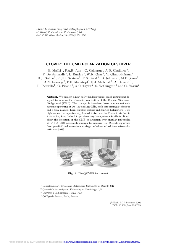
Fig. 1. The Cl OVER instrument.
1
2
3
4
Department of Physics and Astronomy University of Cardiff, UK
Cavendish Astrophysics, University of Cambridge, UK
Università La Sapienza, Roma, Italy
Collège de France, Paris, France
c EAS, EDP Sciences 2005
�
DOI: 10.1051/eas:2005039
Article published by EDP Sciences and available at http://www.edpsciences.org/eas or http://dx.doi.org/10.1051/eas:2005039
�252
1
Dome C Astronomy and Astrophysics Meeting
Introduction
The Cosmic Microwave Background (CMB) provides direct information about the
origin and the evolution of the Universe. In the last 15 years a number of experiments provided us with a vast amount of information, first about the spectral
characteristics of the CMB (COBE), then about the power spectrum of its temperature anisotropies (BOOMERanG, WMAP). However, it is now becoming clear
that the temperature anisotropies alone will not provide the complete picture of
the early Universe. Indeed, the anisotropy must be combined with additional information in order to break the degeneracy in the cosmological models. This can be
done by measuring the CMB polarization caused by Thompson scattering of CMB
photons at the last scattering surface. The signal can be decomposed into a curl
and a curl-free component, known as the B- and E-modes respectively. The amplitude of the E-mode component is about 10% of the temperature anisotropy signal
while the contribution from the B-mode signal is at best an order of magnitude
lower than this. The measurement of B-mode polarization is of critical importance for constraining models of the early Universe, since, in standard models,
the B-mode signal arises in linear theory only from gravitational waves generated
during inflation. On smaller scales, secondary effects, most notably weak gravitational lensing, generate additional B-modes that act as a confusing foreground for
gravity wave searches via this route.
While several experiments have been designed to measure the E-modes – first
detected by DASI (Kovac et al. 2002) – the detection of the B-mode signal constitutes a major technological challenge. CMB experiments, because of their scientific
objectives, require not only the very highest sensitivity, but also a high level of
sidelobe and spectral rejections to be able to detect the weak CMB signal emission, minimising the measurement contamination due to strong sources. Previous
missions have shown how critical are the instrumental systematic effects in order
to get an accurate reconstruction of the CMB anisotropy power spectrum. It is
then in this context that Cl OVER (Taylor et al. 2004) is being developed. This
novel instrument design, with extremely low systematics, will be able to reach the
sensitivity required for detecting the B-mode component to the limit set by confusion from gravitational lensing of the E-mode signal. The targeted resolution of
15 arcmin will allow the measurement of the polarization power spectrum across
an angular multipole range of 20 < l < 1000.
2
Instrument Description
The concept of this instrument relies on three independent sub-systems (Figs. 1
and 2), each dedicated to a specific spectral range coverage centered at 90, 150
and 220 GHz to allow foreground component separation. The bandwidth is set
to about 30% in order to maximise the signal-to-noise ratio. All three are based
on the same design, scaled with frequency. A sub-system comprises a telescope
made of four co-pointed optical assemblies, each focusing its beam onto an 8 × 8
feed horn array located inside a Dewar housing the whole focal plane. The signal
�B. Maffei et al.: The CMB Polarization Observer
253
from each horn goes through a pseudo-correlator with two outputs encoding the
Stokes parameters I, Q and U . The outputs from each corresponding pixel in the
four optical assemblies are then summed incoherently before being detected by
a TES bolometer. Stokes parameters Q and U are measured instantaneously by
modulating the phase in the two arms of the correlation receiver. The intensity
I of the pixel can be obtained from the sum of the detector outputs, but is not
modulated. Modulation of the intensity is achieved by scanning of the array across
the sky.
2.1
Optical Scheme
The optical assembly design follows a Compact Antenna Test Range (CATR)
configuration using two off-axis mirrors, a parabolic primary and a hyperbolic
secondary, resulting in very low beam distortion and cross-polarization across the
focal plane. In order to be able to reach the desired l coverage (20 < l < 1000), the
target resolution has been set to 15 arcmin for all three spectral bands. At 150 GHz,
this is obtained by using a 800 mm primary and a 735 mm × 700 mm secondary
mirror. The optical coupling between the mirrors and the receivers is achieved
through single-moded corrugated horns. These are designed to fully illuminate the
telescope, thus taking advantage of the full resolution while reaching a sidelobe
rejection of at least –25 dB to reduce the straylight contamination. Several designs
have been investigated: a Winston cone profile has been selected due its low crosspolarization, beam Gaussianity and low sidelobe level characteristics (Maffei et al.
2004), giving a 10◦ FWHM beam pattern. GRASP modelling of the antenna beam
using such feed horns (Yassin et al. 2004) suggests that the cross-polarization
should be no higher than –35 dB for the most extreme pixel position in the focal
plane, leading to very low optical systematic effects.
2.2
Focal Plane
For reasons explained later, the whole focal plane is housed in a cryostat. The
four optical assemblies are then built around this cryostat which has four optical
inputs, separated by 90◦ from one another. Each horn receiving the radiation
from the telescope, is followed by a pseudo-correlator unit (Pisano et al. 2004).
In this scheme, the signal from each horn is separated into two independent linear
polarizations through an Orthomode Transducer (OMT), converted to circular
polarization, phase modulated and correlated using hybrid converters and a phase
shifter. The pseudo-correlator has then two outputs D1 and D2 given by:
1
1
(I − Q cos Φ − U sin Φ) and D2 = (I + Q cos Φ + U sin Φ)
2
2
where Φ is the differential phase shift between the two branches of the pseudocorrelator.
The outputs from the corresponding pixels in the four optical assemblies are
summed incoherently before being detected by a background-limited antennacoupled TES (Transition Edge Superconductor) bolometer. Such detectors consist
D1 =
�254
Dome C Astronomy and Astrophysics Meeting
Fig. 2. Left: telescope made of 4 sets of mirrors and the cryostat located at the centre.
Right: horn arrays and focal plane cooled by a pulse-tube cooler attached on the side of
the cryostat and a 3 He/4 He sorption cooler (shown below cold plate).
of a thin superconducting film deposited on a silicon nitride membrane. The device
is biased at the middle of the transition region between the normal and superconducting states. TES detectors are then read out by a SQUID after multiplexing.
Most astronomical experiments require the detection of faint sources in the
presence of large background, this being especially true in observational cosmology. We therefore have to optimise the efficiency of all the components in order
to increase the signal-to-noise ratio. This can be achieved using multimoded optics, where each mode increases the signal reaching the detector. However, this
technique is generally avoided in CMB experiments due to the resulting increase
in cross-polarization and sidelobe levels. Moreover, the antenna beam prediction
and definition of such systems are not as accurate as single-moded systems and
could lead to difficulties during data analysis when reconstructing the CMB power
spectrum. In the adopted design, instead of using proper multimoded optics, the
detectors are collecting four times the same fundamental HE11 hybrid mode selected by the corrugated horn waveguide. This is achieved through the co-addition
of the four beams coming from the four separate single-moded co-pointed optical
assemblies. Such a mode has a very low associated cross-polarization and the resulting beam can be accurately predicted. Thus, there are 256 horns (four 8 × 8 arrays) per sub-system, yet only 64 simultaneously observed pixels using 128 TES
detectors (two pseudo-correlator outputs per pixel). Taking into account the
�B. Maffei et al.: The CMB Polarization Observer
255
background
√ level at Dome C, such a system requires a detector NEP of 4 ×
10−17 W/ Hz achievable with TES bolometers operated at 300 mK. The resulting
expected sensitivity is given in Table 1.
Table 1. Cl OVER sensitivity.
Spectral Band
√
Pixel NET (µK s)
√
Array NET (µK s)
2.3
90 GHz
170
10.5
150 GHz
215
13.4
220 GHz
455
28.5
Thermal Architecture
At infrared, sub/mm and millimetre wavelengths, the thermal background due to
the surroundings and the instrument itself can be comparable and often larger
than the observable signal. For this reason, the whole focal plane needs to be
cooled down to typically 4 K, and the detectors need to be cooled to an even lower
temperature to meet the required performances.
The three cryostats have been designed to be cryogen free for logistical reasons.
Cooling to 2.5 K will be achieved using a pulse-tube cooler, while a 3 He/4 He sorption refrigerator will cool the detector block to around 330 mK (Fig. 2). The four
optical inputs in each dewar will produce a large radiative background. Blockers
and bandpass filters relying on interference filter technology will be used to maximise the in-band transmission, while the unwanted radiation will be rejected in
order to decrease the background load that would otherwise impact the operation
of the cryogenic systems and the detectors.
3
Site and Observations
We propose to install Cl OVER at one of the best mm and sub-mm observing
sites in the world: the French-Italian Dome Concordia station (Dome C) on the
Antarctic Plateau at an altitude of 3200 m. This choice was driven by the needs of
high atmospheric stability and low opacity at high frequency that this site can offer.
During operations we anticipate very little maintenance, and it is intended that
the experiment will run over the Antarctic winter. The design and development
of the instrument has already started. The deployment of the experiment to the
site will be phased over three years, with a fully operational instrument planned
for 2008.
In the first two years of operation we aim to observe a connected region of
sky of a few hundred square degrees. The telescope mount is designed to allow
altitude-azimuth tracking as well as rotation of the entire optical structure around
the pointing axis, so we can adopt a multi-cross scan strategy. This consists of
observing a patch of the sky at a given right ascension and declination range,
scanning over a fixed azimuth range while keeping the elevation constant for a
2-hour period. After this interval, the pointing centre will be changed to one at
�256
Dome C Astronomy and Astrophysics Meeting
the same RA but at a slightly higher declination and the procedure repeated.
This scanning strategy should result in a high degree of cross-linked coverage. In
addition, the whole telescope structure will also be periodically rotated about the
pointing axis to calibrate out instrumental effects and improve the density and
cross-linking of the sky coverage.
4
Conclusion
The main science goal of Cl OVER is to measure the power spectrum of B-mode
polarization on large and intermediate scales, in the multipole range 20 < l <
1000. We aim to make the measurement down to a thermal sensitivity below
the sample variance of the lens-induced B-modes for multipoles l ≤ 200. For a
two-year experiment, observing a near-circular survey region of radius 15◦ , we
expect a thermal noise level after subtraction of foregrounds of 0.24 µK to the
Stokes parameters Q and U per resolution element (15 arcmin by 15 arcmin). For
comparison, the expected rms of Q and U is 2.1 µK at 15 arcmin resolution; √
0.1 µK
of this arises from the B-mode polarization generated by lensing, and 0.3 r µK
from gravitational waves, and is limited by the sample variance of the lensing
signal.
We find that the one-sigma error on the tensor-to-scalar ratio r, computed from
the errors on ClB in the null hypothesis of r = 0, is ∆r = 0.0037. This sets the
detection limit of gravitational waves from a measurement of B-mode polarization
with Cl OVER.
The authors would like to acknowledge the support of the Particle Physics and Astronomy
Research Council for funding this experiment.
References
Kovac, J., et al. 2002, Nature, 420, Issue, 6917, 772
Maffei, B., et al. 2004, to appear in the proceedings of SPIE conference Astronomical
Telescopes and Instrumentation, Glasgow
Pisano, G., et al. 2004, this volume
Taylor, A., et al. 2004, proceedings of the XXXIXth Rencontres de Moriond, Exploring
the Universe (La Thuile, Italy)
Yassin, G., et al. 2004, proceedings of the 15th International Symposium on Space THz
Technology, Amherst, MA, USA
�
 S. Melhuish