Rev. Roum. Sci. Techn.– Électrotechnique et Énergétique
Vol. 65, 3–4, pp. 199–204, Bucarest, 2020
GENERATION AND USAGE OF HIGH VOLTAGE
STEEP-FRONT IMPULSES
MARIAN COSTEA, ILEANA BĂRAN, TUDOR LEONIDA
Key words: High voltage, Impulse generator, Steep-front impulse, Puncture test, Composite insulator steep-front test.
The generation of high voltage steep-front impulses has always been a concern of researchers in the field of high voltage
engineering and electromagnetic compatibility. Obtaining such voltage impulses was imposed by the necessity to simulate real
stresses of insulation in electrical installations or electromagnetic disturbances having such characteristics (high altitude nuclear
electromagnetic pulse, electrostatic discharges or certain switching operations). For the necessity of electromagnetic immunity
tests of civil equipment, the amplitudes of these pulses are usually limited to a few kV, and the circuits that produce them are
based on power electronics. However, for insulation tests, they are of the order of hundreds of kV. The paper presents three
methods to obtain steep high voltage pulses required for testing high voltage insulations. Their advantages and disadvantages
(limitations) are discussed for each of them.
1. INTRODUCTION
In the field of high voltage testing, the generation and use
of steep-front impulses having large amplitudes (tens or
hundreds of kV) become mandatory due to the existence of
several industrial tests recommended by different standards,
such as puncture test in air on glass and ceramic insulators
according to IEC 61211, [1], or steep-front tests for
composite insulators stipulated by IEC 62217 standard, [2].
A second use of steep-front impulses was related to the
occurrence of new equipment such as gas insulated
substations-GIS, [3-5], or gas insulated lines-GIL which
produces very fast transients.
In the electromagnetic compatibility field, steep-front
transient voltages are used to simulate electrostatic discharges
or high altitude electromagnetic pulses.
In recent years, an important number of research studies
addressed the generation of high voltages with steep-front
and the development of suitable measuring instrumentations
and procedures, [6-12]. The paper presents the research
conducted in the High Voltage Laboratory of Politehnica
University of Bucharest in order to obtain high voltage
steep-front impulses, using different solutions.
If the required slope of the impulse is not very high (for
example up to 1000 kV/µs), high voltage steep-front
impulses can be obtained using the conventional Marx
generators. An alternative solution consists in the use of the
Marx generator as a basic source, supplemented with some
dedicated shaping/peaking circuits, such as sphere gaps or
different single stage shaping circuits connected to the basic
generator by multiple spark gaps (MSG). Each of these
solutions is able to produce output voltages with slopes in
the range of 2500 kV/µs...5000 kV/µs or even more. All
these methods will be described and documented in the
paper.
2. ADAPTATION OF A STANDARD IMPULSE
GENERATOR TO OBTAIN STEEP-FRONT
IMPULSES (UP TO 1000 kV/µs)
The generation of high impulse voltages is based for
almost a century on the use of Marx multi-stage generators
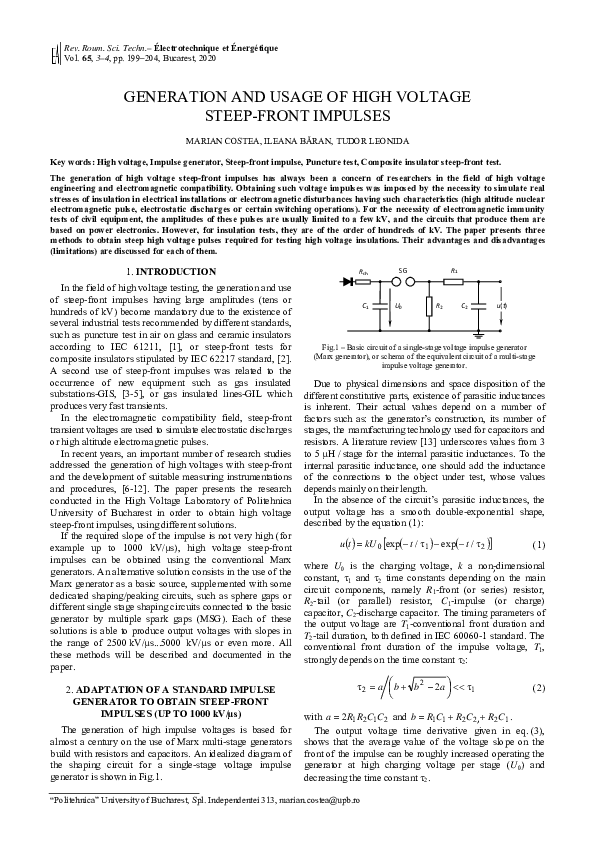
build with resistors and capacitors. An idealized diagram of
the shaping circuit for a single-stage voltage impulse
generator is shown in Fig.1.
Rch
C1
SG
U0
R1
R2
C2
u(t)
Fig.1 – Basic circuit of a single-stage voltage impulse generator
(Marx generator), or schema of the equivalent circuit of a multi-stage
impulse voltage generator.
Due to physical dimensions and space disposition of the
different constitutive parts, existence of parasitic inductances
is inherent. Their actual values depend on a number of
factors such as: the generator’s construction, its number of
stages, the manufacturing technology used for capacitors and
resistors. A literature review [13] underscores values from 3
to 5 μH / stage for the internal parasitic inductances. To the
internal parasitic inductance, one should add the inductance
of the connections to the object under test, whose values
depends mainly on their length.
In the absence of the circuit’s parasitic inductances, the
output voltage has a smooth double-exponential shape,
described by the equation (1):
u (t ) = kU 0 [exp(− t / τ1 ) − exp(− t / τ 2 )]
(1)
where U0 is the charging voltage, k a non-dimensional
,
constant, τ1 and τ2 time constants depending on the main
circuit components, namely R1-front (or series) resistor,
R2-tail (or parallel) resistor, C1-impulse (or charge)
capacitor, C2-discharge capacitor. The timing parameters of
the output voltage are T1-conventional front duration and
T2-tail duration, both defined in IEC 60060-1 standard. The
conventional front duration of the impulse voltage, T1,
strongly depends on the time constant τ2:
τ 2 = a ⎛⎜ b + b 2 − 2a ⎞⎟ << τ1
⎝
⎠
(2)
with a = 2 R1 R2 C1C 2 and b = R1C1 + R2 C 2, + R2 C1 .
The output voltage time derivative given in eq. (3),
shows that the average value of the voltage slope on the
front of the impulse can be roughly increased operating the
generator at high charging voltage per stage (U0) and
decreasing the time constant τ2.
“Politehnica” University of Bucharest, Spl. Independentei 313, marian.costea@upb.ro
�200
Generation and usage of high voltage steep-front impulses
⎤
U ⎡ τ
du
= k 0 ⎢ – 2 exp(− t / τ1 ) + exp(− t / τ 2 )⎥
τ 2 ⎣ τ1
dt
⎦
(3)
.
A sensitivity analysis shows that the front resistor R1
value is determinative for the time constant τ2 and
consequently for T1.
Fig.2 – Front and tail resistors values versus conventional front duration.
As it can be clearly seen from Fig.2, the decrease of R1
value leads to shorter front durations (considering the
capacitances of existent impulse generator described
below). If hypothetically we assume a front resistance value
of R1 = 0.13 Ω / stage (giving an overall front resistance of
2.13 Ω for 6 stages), the front duration equals 0.01 μs. But,
an excessive decrease of the R1 value results in insufficient
circuit damping and occurrence of high frequency
oscillations due to internal parasitic inductances.
The inductances influence was simulated considering the
actual 14 stages Marx generator of the HV Laboratory, with
C1 = 0.32 μF/stage, C2 = 8.96 nF/stage, R1 = 7.24 Ω/stage,
R2 = 217.17 Ω/stage, combination chose to produce a front
time of 0.20 μs. The internal parasitic inductances were
assumed to be equal to 3 μH/stage. The generator was
operated with only 6 stages at 130 kV/stage charging
voltage (780 kV total charging voltage). Three cases have
been considered and the results are plotted in Fig. 3.
(a) Umax = 1159 kV
(c) Umax = 1191 kV
2
generators have intrinsic limitations when set to produce
voltage impulses with very fast front and large amplitudes.
Limitations have several causes such as:
• the large number of stages required to provide the
necessary amplitude of the output voltage, leading to
the increase of the overall parasitic inductance,
• the impossibility to reduce, under a recommended
threshold, the front resistors’ resistance value (R1), a
decisive parameter which control the speed of the
voltage increase at the generator output terminals,
• the additional dynamic resistance introduced by the
generator’s spark gaps (SG) when fired,
• difficulties in ensuring synchronous firing of SG (as
a large number of stages are necessary).
Another problem related to tests performed with steep-front
impulses is the difficulty to measure such fast rising voltages.
Because the ratio between the response time of the potential
divider and the time to peak of the impulse is responsible,
mainly, for the amplitude error of the measured value,
potential dividers with very short response time are required.
Regarding the transmission systems and the necessary
parameters of the measuring device (peak voltmeter,
oscilloscope or transient recorder), one can consider that
proper solutions should be looked for, capable to meet the
demands required by such a signal, since the dynamic
performance of all the quoted devices exhibit non-linear
deterioration with increasing input signal steepness.
The impulse generator equipping the HV Laboratory was
adapted to produce high voltages with average slopes of at
least 1000 kV/µs [14], in order to perform “steep-front test"
on composite insulators, according the IEC 62271 standard.
Passing over the pre-conditioning of insulators, the test
consists in applying a voltage with a slope of at least
1000 kV/µs, to a 50 cm segment of the insulator, delimited
by two strips of copper firmly attached to the insulator’s
core, as presented in the Fig.4; it is supposed that the tested
insulator length between its metallic fittings exceeds 50 cm.
The gap must be subjected to 25 impulses of both positive
and negative polarity with amplitude sufficiently high to
produce an external flashover. If no puncture occurs, the
insulator passes the test.
(b) Umax = 1161 kV
Fig. 3 – Influence of the parasitic
inductances on the shape of the
output voltage:
(a) without HV connection and
without load.
(b) with 10 μH HV connection
and 50 pF capacitive load.
(c) with 10 μH HV connection
and 150 pF capacitive load.
The parasitic inductances, combined with small values of
the equivalent capacity of the load, increase the front
duration compared to its design value, and generate high
frequency damped oscillations superimposed to the double
exponential ideal voltage shape.
Therefore, we can conclude that Marx multi-stage
Fig. 4 – Composite insulator for 110 kV rated voltage prepared for
steep-front impulse test.
Our goal was to obtain a steep-front impulse using a
minimum number of stages and also a minimum charging
voltage of the impulse generator. The design value for the
(conventional) front time was 0.7 µs instead of 1.2 µs (as
for standardized lightning impulse-LI). To lower the front
duration to 0.7 µs, the values of series resistors of each
stage were reduced at 2/3 of the value used to produce the
standard 1.2/50 μs LI, while the impulse and charge
capacitors (C1 and C2) together with the tail resistors (R2)
kept the same values as those used for LI.
�3
Marian Costea et al.
The measured impulses confirmed the expected results.
The impulse generator was operated with 6 stages. The
minimum value of the charging voltage required to obtain
flashovers as a result of the applied steep-front voltage was
130 kV (the maximum charging voltage of the generator
being 250 kV), and the recorded slope of the output voltage
was higher than the required 1000 kV/μs value.
The average value of the peak voltage applied during the
test procedure was 703 kV with a front time of 0.66 µs for
negative polarity (leading to 1065 kV/μs average slope),
and 712 kV with a front time of 0.68 µs for positive
polarity (leading to 1047 kV/μs average slope). It is also of
interest to mention that the average chopping time was
placed around 1 µs.
A couple of voltage recordings obtained during these
tests is shown in the Fig. 5.
201
itself is a two-port circuit with the longitudinal branch
consisting of the inductance L in series with the resistor R3,
and the transversal branch which can be resistive (R),
capacitive (C), or a combination (RC). In the HV
Laboratory we use the RC transversal branch solution
represented in Fig.6; the branch consists of the resistor Rd in
series with the capacitor Cd. The inductance L and the
resistance R3 can be intentional circuit’s components, or
parasitic components of the HV connection between IG and
the transversal branch of the peaking circuit.
1
MSG
L
R3
3
Rd
Û = U 2
C2
ua(t)
Cd
2
4
Peaking circuit
Basic IG
Fig. 6 – A peaking circuit with RC output.
The steep-front impulse voltage provided by the
arrangement and applied to the object under test, ua(t), is
generated in two stages: (1) following the firing of the IG
the voltage between terminals 1 and 2 increases from 0 to
the peak voltage U2; (2) if U2 equals the disruptive voltage
set for the MSG, the peaking circuit is connected to the IG
through the chain of disruptive discharges which occur
inside the MSG, and the output voltage ua(t) appears
between the terminals 3 and 4. As it was proved in [15], if
the MSG switching is instantaneous, then the output voltage
ua(t) is given by eq. (4):
⎧
⎪C
u a (t ) = U 2 ⎨ e
⎪Cd
⎩
t
⎤
⎡
−
1
τ
⎢1 −
⋅ e ⋅ cos(ωt − ψ )⎥ + "
⎥
⎢
1− k 2
⎦
⎣
R
2k
"+ d ⋅
Re
1− k 2
t
−
τ
⋅e
⎫
⎪
⋅ sin ωt ⎬
⎪⎭
(4)
where:
Re = R3 + Rd – equivalent resistance,
Ce = (C2·Cd)/(C2+Cd) – equivalent capacitance,
τ = (2·L) / Re – damping time constant,
Fig. 5 – Steep-front impulses of positive (a) and negative (b) polarity
during tests performed on a composite insulator (110 kV rated voltage).
The approach proves the possibility to perform such a
test using a classic voltage impulse generator, the
intervention consisting only in reducing the value of the
series (front) resistances. Not excessive heating of these
resistors has been observed.
3. USING RC PEAKING CIRCUIT TO OBTAIN
STEEP-FRONT IMPULSES
An alternative solution to obtain HV steep-front impulses
is to use a classical impulse generator (IG) as basic voltage
source, supplemented with an auxiliary shaping circuit
connected to the IG output via a multiple spark-gap (MSG).
The peaking circuit is a single stage circuit that can have
different schemes; MSG connects IG to the peaking circuit
with a very short switching time. An option for the peaking
circuit is represented in Fig. 6: the output of the basic IG is
connected to terminals 1 and 2, and the peaking circuit
ω = 1 / (L ⋅ Ce ) − (Re / 2 ⋅ L )2 – pseudo-angular frequency;
(
)
k = Re / 2 L / Ce – circuit damping factor;
ψ = atan (1/ω ⋅ τ ) = atan ⎛⎜ k/ 1 − k 2 ⎞⎟ – phase angle.
⎠
⎝
The equation (4) is valid if the peaking circuit is
under-damped, therefore the damping factor should be in
the range k ∈ (0, 1) . It is easy to obtain the output voltage
for the case of a peaking circuit with pure resistive or
capacitive transversal branch from this equation. If
C d → ∞ (resistive transversal branch) in eq. (4), Ce will be
replaced by C2. If Rd = 0 (capacitive transversal branch) in
eq. (4), Re will be replaced by R3.
In order to compare the three possible options for the
transversal branch (namely R, C or RC), a sensitivity study
was performed centered to the following parameters of the
output voltage: maximum peak voltage (for a given
charging voltage), maximum and average slope, time to
reach the maximum slope, and time to crest.
�202
Generation and usage of high voltage steep-front impulses
As it was proved, for a given setting of the IG, MSG and
the longitudinal peaking circuit’s branch, a RC transversal
branch has some advantages compared to R or C options: it
provides the highest values for the peak voltage and the
maximum voltage derivative, as well as the highest peak
voltage value for a given intended value of the average
slope. Consequently, the RC option has been chosen and a
method to design the peaking circuit has been developed.
This method is based on the following assumptions: the
capacitance C2 in Fig. 6 is the charge capacitance of the
basic IG, the longitudinal branch of the peaking circuit has
only the inductance L, which depends on the length of the
HV connection between the IG and the transversal branch
Rd-Cd, the resistance R3 being neglected.
The design method is based on the following input data:
• utilization factor of the peaking circuit, c p = U p /U 2 ,
defined as the ratio between the peak output voltage,
Up =max {ua(t)} and the peak input voltage, U2;
• intended average rise slope, S av = U p /T p , where Tp
is the time to peak of the output voltage ua(t);
• intended peak value of the output voltage, Up.
Accordingly, the design method outputs the following results:
• the values of the circuit elements Rd and Cd;
• the value of the voltage U2 at the peaking circuit input,
required to obtain the desired steep-front impulse
parameters (intended peak value and average rise
slope defined above).
The utilization factor cp should be set close to unity for
two reasons: first, if the peaking circuit is under-damped,
the overshoot will increase when increasing the value of the
utilization factor, and secondly, keeping cp close to unity
leads to a smooth shape of the steep-front impulse, without
oscillations on the impulse’s tail.
Our intention was to obtain a steep-front impulse with an
average rise slope of about 5000 kV/µs using 4 stage of the
existing IG with 250 kV maximum charging voltage per
stage. The IG was set to produce standard LI. For the
following input data: C2 = 2.25 nF (the equivalent value of
the discharge capacitances of the IG operating with 4 stages),
L = 4 µH, Up = 500 kV, and choosing an utilization factor
equal to 1.0, the evaluation for the output data is
Cd =1011 pF, Rd = 94.7 Ω and a necessary peak value
U2= 505 kV at the input in the peaking circuit. The shape of
the resulting steep-front impulse is plotted in Fig. 7.
500
450
400
350
300
250
200
150
100
50
0
0
0.05
0.1
0.15
0.2
0.25
0.3
0.35
0.4
0.45
0.5
t [µs]
4
a capacitive damped divider with Cd = 590 pF and
Rd = 290 Ω has been used as transversal branch of the
peaking circuit. The reason why such a solution was
adopted is related to the difficulty of building HV circuit
components at exactly required values and which can
withstand, in addition, the electrical stress to which such a
transversely installed element will be subjected.
The difference between the design and the actual values
results is acceptable for the capacitance Cd but due to the
higher value of Rd, the peaking circuit will be over-damped.
Even in these conditions, using a self-ignition MSG (10
gaps of 1...3 cm between 11 spheres of 10 cm diameter, in
air at atmospheric pressure), we have obtained impulses
with time to peak shorter than 100 ns. An example of such a
steep-front impulse is given in Fig. 8.
All the tests performed at different charging voltages and
different settings of the MSG, have proved the ability of the
design method exposed above to provide appropriate
estimations for the peaking circuit settings in order to
obtain steep-front impulses.
Fig. 8 – Measured negative fast front impulse with 250 kV
peak value and 75 ns time to peak.
A second challenge that adds to that of producing a steep
front impulse is to measure it. To have a measuring system
with fast response, we built a potential divider based on
electric field sensor (the high voltage arm was an air gap
between two well geometric defined electrodes: spherehemisphere), [15]. The 50 Ω output of the low voltage arm
(having R-C structure) was connected to the input of a fiber
optic transmission system (of 100 MHz bandwidth, rise
time 3.5 ns). The potential divider itself was investigated in
order to evaluate the parameters of its step-response, the
necessary damping resistor value and the scale factor. This
last parameter was determined for an input impulse with the
shape 0.1/50 µs. The following parameters have been
obtained by processing the step-response of divider:
experimental response time, TN=13.3 ns, stabilization time,
ts = 255 ns and partial response time, Tα = 20 ns. The scale
factor of the divider was 1492. The measuring device was a
digital oscilloscope with 150 MHz analogue bandwidth and
100 MSa/s sampling rate.
Comparing the measured and calculated response of the
system for a 0.1/50 µs voltage impulse, the amplitude errors
did not exceed 5%.
Fig. 7 – Simulated steep-front impulse for cp = 1.0.
4. USAGE OF SPHERE-GAP AS PEAKING CIRCUIT
For a utilization factor cp = 1.1, Up = 500 kV and
Sav = 5100 kV/µs average rise slope, the resulting output
data are Cd =635 pF, Rd = 87.2 Ω and U2 = 458 kV. For
practical reasons, a compromise solution was adopted:
Another possibility to obtain a high voltage steep-front
impulse is presented in Fig. 9. A sphere-gap (SG2), in series
with the tested equipment, is connected to the output
terminals of a basic IG. The impulse amplitude depends on
�Marian Costea et al.
the output voltage of the basic IG correlated with the length
of the sphere-gap (SG2). In order to obtain a very fast front
of the impulse, the spheres diameter and the sparking
distance should be set in order to maintain a (practical)
homogeneous electric field. In other words, SG2 should be
operated with sparking distances smaller than the sphere
radius.
Rch
SG1
R1
SG2
C1
U0
R2
C2
EUT
Basic impulse generator
To measuring
system
Sphere-gap
peaking circuit
Fig. 9 – Steep front impulse generator based on sphere-gap peaking
circuit (EUT- equipment under test).
Generally, this arrangement is used to perform tests on
small size insulators, for example tests to check of the
puncture voltage in atmospheric air for cap-and-pin insulators.
Our measuring system does not comply entirely with the
severe requirements of IEC 61211 (for example, a response
time ≤ 5 ns and a first partial response time ≤ 3 ns for the
measuring system without instrument). The instrument
(digital recorder) complies partially with the requirements:
its rise time is equal to 7 ns and the resolution is of 12 bits.
Only the sampling rate (which is of 100 MSa/s) is lower
than the recommended one (500 MSa/s). But, even in these
conditions, comparative measurements can be performed.
As an example, for a triangular shape impulse with the peak
time Tp and a measuring system with monotonic and
positive response time, TN, the relative amplitude error is
δU= – TN/Tp [15].
For this experiment we have used a 6 stages impulse
generator and a maximum charging voltage of
200 kV/stage, operated with only 4 stages. The generator
was set to produce standardized lightning impulse (LI)
voltage. At the output of the IG we have connected a
200 mm diameter sphere-sphere gap in series with a cap
and pin toughened glass insulator. The sparking distance
was set at 40 mm and 60 mm respectively, in order to keep
a practical homogeneous electric field inside the gap.
203
An example of steep-front voltage recorded at the pin
terminal of the tested insulator is presented in the Fig. 10;
the time parameters have been evaluated following the rules
recommended for the LI.
For a charging voltage per stage between 50 kV and
100 kV, the conventional front time do not exceed 200 ns
for the sparking distance of 60 mm and 350 ns for the
sparking distance of 40 mm. The impulse voltage slope
varies between 1000 kV/µs (40 mm sparking distance) to
over 1800 kV/µs (60 mm sparking distance) increasing with
the increase of the sparking distance, as it has been
observed.
From the experiments that have been performed using
this solution, some conclusions can be drawn: (1) two
impulses with the same crest voltage, but produced using
different sparking distances, have practically the same
shape; (2) for a set value of the IG charging voltage, the
slope increases with the sparking distance, especially due to
the amplitude increasing correlated with the decrease of
front duration. This effect is illustrated by the comparison
between the two chopped impulses shown in the Fig. 11.
U [kV]
5
Fig. 11 – Steep-front impulses obtained with the same charging voltage
(95 kV) and different lengths for the sphere gap.
(a)
(b)
Fig. 12 – Flashover of the cap-and-pin insulator under test while applying
(a) standard LI impulse, and (b) steep front impulse.
Fig. 10 – Steep-front impulse obtained using a sphere-gap as peaking circuit.
The amplitude of the LI provided by the basic generator
has been coordinated with the voltage-time characteristics
(Ud-Td) of the sphere gap, in order to locate all the
disruptive discharges occurring between the spheres on the
front of the LI (100% flashover probability zone of the
Ud-Td characteristics).
The impulses which have been obtained using the same
charging voltage (95 kV), but with different sparking
distances, and applied to a cap-and-pin insulator, have been
leading to flashovers that can be seen in Fig. 12. No
puncture of the insulator was recorded, but the goal of the
experiment did not intend to reach this event.
Generally, such an insulator must withstand, without
puncture, a peak voltage equal to 2.5 p.u., the reference being
the LI negative flashover voltage of the same tested object.
The comparison of the two steep-front impulses reported
in Fig. 11 highlights the followings: the amplitudes of the
impulses differs with about 27 kV, the rise time is the same,
�204
Generation and usage of high voltage steep-front impulses
the slope is higher with about 200 kV/µs for the 60 mm
sparking-distance, and the difference between the time to
chopping values is about 40 ns, the time to chopping being
larger for the sparking distance of 40 cm.
A special mention should be done relative to the
differences in the visual aspect of the flashovers in Fig. 12:
the flashover under steep-front impulse (Fig. 12.b) exhibits
several discharge channels compared to the flashover under
standard LI (Fig. 12.a), which signals possible differences
induced by the increase of the voltage slope on the
mechanism of the discharge development. In the upper part
of Fig. 12.b is also visible the discharge between spheres,
the picture being taken in dark conditions.
5. CONCLUSIONS
The paper presents three possible solutions to obtain
steep front impulses based on an existing classical impulse
generator (Marx generator): by adapting an existing one by
changing the series resistances, by adding at its output a
single peaking stage adequately designed and finally by
using a sphere gap as peaking circuit.
The first two methods make possible the control of the
average slope of the impulse voltage by means of analytical
calculations. The last available solution can control the
average slope only by experiment, choosing a sphere gap
with given diameters and adjusting the distance between
spheres in order to obtain the required amplitude of the
impulse voltage, correlated with a given time to crest. In
this case it would be recommended to establish, with a
sufficient number of tests, a table of values useful to avoid
a long-lasting probing phase.
ACKNOWLEDGMENTS
The entire experimental tests were performed using the
High Voltage Laboratory facilities from Politehnica University
of Bucharest which founder was academician Gleb Drăgan.
6
Received on April 8, 2020
REFERENCES
1. *** Insulators of ceramic material or glass for overhead lines with a
nominal voltage greater than 1000 V - Impulse puncture testing in
air, IEC 61211:2004 Std.
2. *** Polymeric HV insulators for indoor and outdoor use – General
definitions, test methods and acceptance criteria, IEC 62217:2012 Std.
3. *** Monograph on GIS very fast transients, CIGRE-Brochure no. 35, July
1989.
4. M. Muhr, S. Pack, Fast transient overvoltages on a GIS-bushing, 7th
Intl. Symp. on High Voltage Engineering (ISH) Dresden,
Germany, 1991.
5. W. Boeck, R. Witzman, Main influences on the fast-transient
development in gas-insulated substations, 5th Intl. Symp. on High
Voltage Engineering (ISH), Braunschweig, Germany, 1987.
6. T.F. 15.09, Review of research on nonstandard lightning voltage waves,
IEEE Trans. on Power Delivery, 9, 4, pp. 1972–1981 (1994).
7. J. Fleszynski, E. Sojda, A. Tyman, K. Koruba, Steep-front impulse
voltage tests of composite insulators, 13th Intl. Symp. on High
Voltage Engineering, Delft, Netherlands, 2003.
8. K. Marimuthu, S. Vynatheya, N. Vasudev, P. Raja, Quality analysis of
ceramic insulator under steep front impulse voltage, 20th National
Power Systems Conference (NPSC), Tiruchirappalli, India, 2018.
9. K. Wieczorek, J. Fleszyński, Steep-front impulse voltage in diagnostic
studies of composite insulators, IEEE Transactions on Dielectrics
and Electrical Insulation, 23, 3, pp. 1236–1241 (2016).
10. N. Femia, G. Lupò, C. Petrarca, V. Tucci, M. Vitelli, Performances of
high-voltage glass insulators subjected to fast transient
overvoltages, European Trans. on Electrical Power, 6, 2, pp. 119–
124 (1996).
11. W. Hauschild, E. Lemke, High-Voltage Test and Measuring
Techniques, 2nd ed., Springer, 2019.
12. J. Hlavacek, M. Knenicky, Very fast high voltage impulse generator,
19th Intl. Scientific Conf. on Electric Power Engineering, Brno,
Czech Republic, 2018.
13. N. Hylten-Cavallius, High voltage laboratory planning, 2nd ed., E.
Haefely, Basel, 1988.
14. M. Costea, Ileana Băran, T. Leonida, Special dielectric tests for
composite insulators, Bul. Inst. Politehnic Iaşi, 62 (66), 1, pp.39–50
(2016).
15. M. Costea, Research on aspects of extending insulation coordination
taking into account very fast overvoltages (in Romanian),
Polytechnic Univ. of Bucharest, PhD Thesis, 1998.
�
 Marian Costea