COPERNICUS SENTINEL-1 SATELLITE AND C-SAR INSTRUMENT
Aniceto Panetti (1), Friedhelm Rostan (2), Michelangelo L’Abbate(1), Claudio Bruno(1), Antonio Bauleo (1),
Toni Catalano(1), Marco Cotogni (1), Luigi Galvagni(1), Andrea Pietropaolo(1), Giacomo Taini(1),
Paolo Venditti(1), Markus Huchler(2), Ramon Torres(3), Svein Lokas(3), David Bibby(3)
(1)
Thales Alenia Space Italia - Via Saccomuro 24, 00131 Rome, Italy, Email:
Aniceto.Panetti@Thalesaleniaspace.Com, Michelangelo.LAbbate@Thalesaleniaspace.Com,
Claudio.Bruno@Thalesaleniaspace.Com, Antonio.Bauleo@Thalesaleniaspace.Com,
Toni.Catalano@Thalesaleniaspace.Com, Marco.Cotogni@Thalesaleniaspace.Com,
Luigi.Galvagni@Thalesaleniaspace.Com, Andrea.Pietropaolo@Thalesaleniaspace.Com,
Giacomo.Taini@Thalesaleniaspace.Com, Paolo.Venditti@Thalesaleniaspace.Com
(2)
EADS Astrium GmbH, D-88039 Friedrichshafen, Germany, Email:
Friedhelm.Rostan@astrium.eads.net, Markus.Huchler@astrium.eads.net
(3)
ESA/ESTEC – Keplerlaan 1 Postbus 299 AG 2200 Noordwijk, The Netherlands, Email:
Ramon.Torres@esa.int , Svein.Lokas@esa.int, David.Bibby@esa.int
ABSTRACT
The Copernicus Sentinel-1 Earth Radar Observatory, a
mission funded by the European Union and developed
by ESA, is a constellation of two C-band radar
satellites. The satellites have been conceived to be a
continuous and reliable source of C-band SAR imagery
for operational applications such as mapping of global
landmasses, coastal zones and monitoring of shipping
routes. The Sentinel-1 satellites are built by an industrial
consortium led by Thales Alenia Space Italia as Prime
Contractor and with Astrium GmbH as SAR Instrument
Contractor.
The paper describes the general satellite architecture,
the spacecraft subsystems, AIT flow and the satellite
key performances. It provides also an overview on the
C-SAR Instrument, its development status and prelaunch SAR performance prediction.
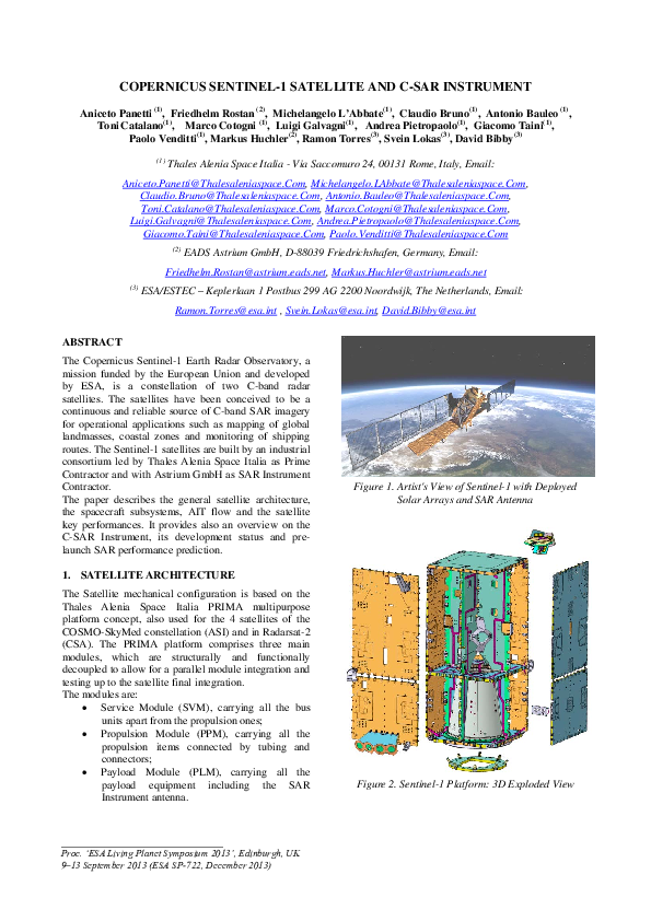
Figure 1. Artist's View of Sentinel-1 with Deployed
Solar Arrays and SAR Antenna
1. SATELLITE ARCHITECTURE
The Satellite mechanical configuration is based on the
Thales Alenia Space Italia PRIMA multipurpose
platform concept, also used for the 4 satellites of the
COSMO-SkyMed constellation (ASI) and in Radarsat-2
(CSA). The PRIMA platform comprises three main
modules, which are structurally and functionally
decoupled to allow for a parallel module integration and
testing up to the satellite final integration.
The modules are:
Service Module (SVM), carrying all the bus
units apart from the propulsion ones;
Propulsion Module (PPM), carrying all the
propulsion items connected by tubing and
connectors;
Payload Module (PLM), carrying all the
payload equipment including the SAR
Instrument antenna.
_____________________________________
Proc. ‘ESA Living Planet Symposium 2013’, Edinburgh, UK
9–13 September 2013 (ESA SP-722, December 2013)
Figure 2. Sentinel-1 Platform: 3D Exploded View
�Most of the PPM is enclosed in the SVM, being
integrated into the cone section interfacing the
Spacecraft to Launcher Adapter, while the PLM is
mounted onto the SVM allowing the payload
units/appendages allocation through four lateral panels
and the upper platform. Fig 1 & 2 show some views of
the overall satellite and the platform design.
2. SATELLITE SUBSYSTEM
The Satellite platform provides the following functional
subsystems:
a) Structure Subsystem (STR)
The STR provides the accommodation for all platform
and payload units. A box type structure has been
adopted using external aluminium sandwich material,
with a central structure in CFRP. A modular approach
has been taken whereby the payload is mounted to a
dedicated part of the structure, allowing separate
integration & test of the payload before integration to
the main part of the structure carrying the platform
units. This has many advantages for the overall AIT
process.
b) Thermal Control Subsystem (TCS)
The TCS provides control of the thermal characteristics
and environment of the Satellite units throughout all
phases of the mission. In general the TCS is passive,
with the control provided by means of standard
techniques such as heat pipes, radiators and MLI.
Survival heaters are provided to prevent units becoming
too cold during non-operative phases.
c) Avionics Subsystem (AVS)
The AVS performs both Data Handling &
Attitude/Orbit Control functions. This is realized
through the concept of an integrated control system that
performs the control of the platform and payload. The
AVS performs all data management & storage functions
for the Satellite, including TM/TC reception and
generation, subsystem & unit monitoring, autonomous
switching actions and synchronization. The AVS
includes the AOCS processing and the interfaces to the
AOCS sensors Star trackers, fine sun sensors, and fine
gyroscope and actuators, 4 reaction wheels, 3
torquerods, 14 thrusters and 2 solar array drive
mechanisms. Telecommand data will be received from
the TT&C subsystem and will be decoded and
deformatted in the AVS. The AOCS comprises all
means to perform transfer and on-orbit control
maneuvers and to control all necessary Satellite attitude
and antenna pointing states during all mission phases,
starting at separation from the launcher until de-orbiting
of the Satellite at end of life. This includes the attitude
steering of the LEO Satellite to provide both yaw and
roll steering capability. At present, a dedicated precise
orbit predictor is implemented within the AOCS, in
addition to making use of the data uploaded to the
payload by the GPS constellation.
The AOCS is supported by a very reliable FDIR
scheme.
d) Propulsion Subsystem (PRP)
The PRP based on 14 RCT located in 4 different sides
of the spacecraft, provides the means to make orbit
corrections to maintain the requested tight orbit control
throughout the mission. Initially, corrections are
required to reach the final orbit position after separation
from the launcher. During the mission, some infrequent
corrections to the orbit are necessary to maintain the
requirements upon the relative and absolute positioning
of individual Satellite. The thrusters located on the –Z
side of the satellite are specifically dedicated to Attitude
control during the Safe Mode.
e) Power Subsystem (EPS)
The EPS is responsible for management of the power
distribution, including power generation (via solar
array), power storage (via battery) and power
distribution to individual subsystems & units. A power
control and distribution unit (PCDU) and a C-SAR
Antenna Power Supply unit (CAPS) are foreseen to
handle these functions. The PCDU is designed to
provide adequate grounding, bonding & protection for
the overall electrical system (e.g. by use of fuses) and
must also be integrated into the Satellite FDIR concept
to ensure that adequate power resources and
management are available in the event of onboard
failures. Li-Ion battery technology has been selected for
the batteries in view of the large benefits offered in
terms of mass and energy efficiency.
f) Telemetry, Tracking & Control (TT&C)
The TT&C subsystem operating in S-band, receives the
up-linked data from the TT&C stations as well as downlinking the TM data from the Satellite. Two antennas
are required to provide the full coverage, one for
nominal (earth pointing) operations, one for use in nonnominal cases (zenith pointing).
h) Optical Communication Payload (OCP)
The OCP will be embarked on S-1A and S1-B
spacecrafts, to provide Data Relay connection towards
GEO Satellite by means of Laser Communication
Terminal. The OCP is an ESA Customer Furnished Item
and it will be operated in addition to the baseline PDHT
system.
g) Payload Data Handling and Transmission (PDHT)
Data generated by the Sentinel-1 satellite payload (CSAR) will be stored, formatted and transmitted to the
ground stations by the PDHT subsystem. The PDHT
includes all the necessary functions to interface different
sources at different data rate, for the data acquisition,
storage, formatting, and RF transmission (X-Band
communication equipment) to Ground Stations. The
PDHT interfaces also the OCP for data transmission to
GEO satellite. During downlink operations, stored data
are formatted according to the CCSDS standard (AOS
�Figure 3. Sentinel-1 Satellite Stowed View (+Y Side)
Space Data Link Protocol) and transmitted towards the
X-Band transmission assembly, where 4D-TCM 2.5
bit/s/Hz coding, 8-PSK modulation, up-conversion to XBand, power amplification and RF filtering are
executed. In order to provide flexibility in the downlink
operation, the PDHT is designed with two X-Band
independent links. The PDHT provides an overall
input/output throughput of about 1950 Mbps, with a
payload input data rate of 2*640 Mbps (multipolarization acquisition) or 1*1280Mbps (singlepolarization acquisition) and a transmitted symbol rate
of 2*112 MSps. The data storage capacity is higher than
1410 Gbits EoL. The antenna isoflux coverage zone
provided is about ±64 deg with respect to the nadir to
allow link establishment with ground starting from the
ground antenna elevation angle of 5 deg above the
horizon.
h) Harness Subsystem (DPH)
Sentinel-1 Harness Subsystem provides the electrical
interconnections necessary to allow the distribution of
power and signals. It is composed of the following main
components:
DC Harness for Unit & Heater power supply
TM / TC signals distribution (thermistors
acquisition, status telemetries, discrete
commands, serial digital, broadcast pulses,
etc.)
RF Harness including Waveguides, coaxial
cables and RF miscellaneous
NEA / Thermal Knife Harness for deployment
activation of SAR antenna, Solar Panels
appendages
1553 Data BUS Harness for data exchange
between Bus Controller (BC) resident in SMU
and Remote Terminals (RT)
Launch Vehicle Umbilical Connector Harness
for on-ground Spacecraft to launch vehicle
interconnection
Figure 4. Sentinel-1 Satellite Stowed Views (+Z and –Y
Sides)
3. AIT ACTIVITIES AND FLOW
The spacecraft level AIT activities concern all the
operations related to the build-up and testing of the
PFM spacecraft. The spacecraft tests involve :
a) Spacecraft Mechanical Tests
Static Load (during sine test),
Sine Vibration and Acoustic Vibration,
Fit Check & Separation Shock (with the launcher
interface adaptor),
Appendages Deployments (namely SAR antenna
and Solar Arrays),
Alignments (of all alignment critical elements),
Mass Properties measurements (namely centre of
mass and inertia moments),
b) Spacecraft Propulsion Tests
Latching Valves Activation (TM-TC)
Thrusters Activation and Flow Rate (TM-TC)
Pressure Transducer Calibration Check (TM-TC)
Thrusters’ Valves Leak Test
Latching Valves Leak Test, overall Leak Test.
Figure 5. Sentinel-1 Satellite entering the Thermal
Vacuum Chamber
�S/C
Integr./align.
Sine
Vibration
LV I/F
Sep.Shock
Sys Ver.
Test-1
Initial
Func. Tests
Acoustic
Vibration
SAW integr./
/deploy.
Mass
Properties
Appendages
Deployment
Final
Func. Tests
Thermal
Vacuum
& Balance
EMC
CE/CS
Sys Ver.
Test-3
Sys Ver.
Test-2
SAR, TT&C,
PDHT Ant’s
Integr./alig.
EMC RE/RS
& RFC
FAR
Colours Legend
TAS-Rome
TAS-Cannes
Centre Spatial
Guyanais
Launch
Campaign
Figure 6. Sentinel-1 AIT Flow and Organisation of
Activities
c) Spacecraft Thermal Tests
Thermal Balance Test (TBT) (for thermal
mathematical model correlation),
Thermal Vacuum Test (TVT),
d) EMC Tests
Conducted Emission (CE),
Conducted Susceptibility (CS),
Radiated Emission (RE),
Radiated Susceptibility (RS),
e) RF Compatibility (RFC)
Antenna Coupling, (Antenna Farm Mock-up).
Radiated Auto-Compatibility.
f) Electrical Verification
Integration Tests,
Integrated Subsystem Tests (ISST),
SES – PDHT Interface Tests,
Integrated System Tests (IST),
Spacecraft Health Tests (SHT),
Power Budget,
Polarity verification (of all sensors
actuators).
Figure 7. Sentinel-1 Spacecraft during Initial
Functional Tests
and
4. SATELLITE KEY PERFORMANCES
Sentinel-1
Satellite
key
performances
and
characteristics are summarised in the following list.
Max Mass at Launch: 2172kg (propel.: 154kg)
SAR Antenna dimensions: 12.30 x 1.02 m
(LxW)
Generated Power: 6140W(BOL)-5900W(EOL)
Main Body Dimensions: 3.4 x 1.3 x 1.3 m
Satellite Envelope Dimensions: 3.9 x 2.6 x 2.5
(incl. stowed appendages)
Deployed solar arrays dimension: 21 m
Orbit: SSO LEO orbit @ 692 km altitude
Orbital Period: 98.6 min (max eclipse 19 min)
Lifetime:7years (12 for battery and propellant)
S/L BUS&P/L Reliability:0.860&0.888@7y.
Satellite Availability over lifetime: 0.975
Avionics: Integrated data handling, control &
AOCS system
Navigation & Ref. time: GPS constellation,
dual frequency receiver
Operative autonomy: 96 h
Attitude stabilization: 3 axes, Gyro stellar
Attitude Profile:, Geo-Centric, Sun-Pointing,
Yaw and Roll Steering capability
Nominal Flight Attitude: Right Looking
Attitude accuracy: < 0.01° each axis
Attitude Knowledge: < 0.003° each axis
Satellite Orbit Knowledge: with GPS: better
than 10 m (3 sigma) in each axis accuracy on
real-time processed data vectors and 5 cm in
post-processing
Propulsion: Mono-propellant (Hydrazine), 14
thrusters, 6 (orbit control)+8 (attitude)
Structure: Box of aluminium sandwich panels
+ CFRP central structure
Thermal Control: Mainly passive, standard
techniques
Power Bus Regulated Voltage: 28 V
Power Bus Unregulated Voltage range: 46 V to
65 V
Battery: 240 Ah @65 V, Li-Ion battery
Solar Array cell type: GaAs
TT&C: S-Band, zenith/nadir antennas
TT&C antenna orientation: Zenith/Nadir
Launcher: Soyouz ST (from Kourou).
�5. C-SAR INSTRUMENT
The C-SAR instrument for the Sentinel-1 mission is
composed of two major subsystems:
the SAR Electronic Subsystem (SES)
the SAR Antenna Subsystem (SAS)
The radar signal is generated at baseband by the digital
chirp generator and up-converted to C-band within the
SES. This signal is distributed to the High Power
Amplifiers inside the EFE Transmit/Receive Modules
via the beam forming network of the SAS. Signal
radiation and echo reception is realized via the same
antenna using slotted waveguide radiators. In receive,
the echo signal is amplified by the low noise amplifiers
inside the EFE Transmit/Receive Modules and summed
up using the same network as for transmit signal
distribution. After filtering and down conversion to
baseband inside the SES, the echo signal is digitized,
formatted and compressed for recording.
a) SAR Electronic Subsystem (SES)
The fully redundant SAR Electronics Subsystem (SES)
provides all radar control, IF/RF signal generation and
receive data handling functions. It comprises three basic
elements, the Integrated Control Electronics (ICE), the
Transmit Gain Unit (TGU) and the Mission Dependent
Filter Equipment (MDFE). It hosts the SAR Instrument
Software and is responsible for control and timing of the
whole SAR instrument as well as for the communication
with the platform. Apart from this it provides TX signal
generation and up-conversion as well as filtering, downconversion, compression and formatting of the SAR
echo data. A block diagram of the SES can be seen in
Fig.8.
Figure 9. SES Protoflight Model (PFM) Mounted on
SAR Instrument Panel
b) SAR Antenna Subsystem (SAS)
The SAS Protoflight Model is a is a deployable planar
phased array antenna carrying 280 phase centres, which
are organized in 14 SAS Tiles with 20 dual polarized
phase centres each. The antenna comprises three
elements, i.e. the SAS Centre Panel, which carries two
SAS Tiles and which is mounted on the top of the
spacecraft and two foldable SAS Wings carrying 6 SAS
Tiles each. During launch the two SAS Wings are
stowed on the two adjacent sides of the spacecraft and
held by 6 Hold-Down and Release Mechanisms
(HRMs) each.
A SAS Tile forms the smallest entity of the SAR
Antenna Subsystem and contains all the basic
functionality of the whole antenna. An electrical block
diagram of a SAS Tile is given in Fig.10.
APDN
EPDN
TA
TRM 1H
TX
TX Divider
1:4
Tx
For 1:7
Aft 1:7
RxH/RxV
Combiner
1:2
TRM 1V
1:10
RxH
TRM 2H
RxH
1:14
EFE
Card
RxV
TRM 2V
RxV
1:14
EFE1
...
EFE
EFE10
TRM
Temperature
HK
SYNC
CLOCK
TxGate
RxGate
DATA
Antenna Control Bus A1
Antenna Control Bus B1
TCU
TCU
Antenna Timing Bus A1
TPSU 1
TPSU 2
Supply Outlets for EFEs
1,2,3,4,5
Supply Outlets for EFEs
6,7,8,9,10
Antenna Timing Bus B1
Antenna Control Bus A1
TPSU Voltage/
Temperature HK
Antenna Control Bus B1
TPSU Ctrl
(TA On/Off)
Antenna Control Bus A2
Antenna Control Bus B2
Antenna Timing Bus A1
Antenna Timing Bus B1
Antenna Timing Bus A2
TPSU2 Power Tile (8...14)
TPSU2 Power Tile (2...7)
TPSU2 Power Tile1
TPSU1 Power Tile (8...14)
TPSU1 Power Tile (2...7)
TPSU1 Power Tile1
Thermistor-IF Tile (1...14)_1
Thermistor-IF Tile (1...14)_3
Thermistor-IF Tile (1...14)_2
Heater Power Tile (1...14)_2
TCU-B Power (8...14)
TCU-A Power 1
TCU-B Power (2...7)
TCU-A Power (2...7)
TCU-A Power (8...14)
The Protoflight Model (PFM) of the fully integrated
SES can be seen in Fig. 9. One can clearly distinguish
the two large and black ICE boxes as well as the flat
TGU mounted on the SES Flight Panel in Aluminium
sandwich technology.
The SES PFM has completed its performance and
environmental test campaign and has been delivered for
integration into the SAR Instrument PFM in the first
weeks of January 2013.
TCU-B Power 1
Figure 8. SAR Electronic Subsystem (SES): Functional
Block Diagram (only one redundancy chain shown)
Heater Power Tile (1...14)_1
Foil Heater
Heater
&Foil
Temp.
Sensor
& Temp. Sensor
Antenna Timing Bus B2
Figure 10. SAR Antenna Subsystem (SAS): Functional
Block Diagram of a SAS Tile
The signal received from the SES is distributed by the
Azimuth Plane Distribution Network (APDN) to the 14
Tiles. There it is amplified by a cold-redundant Tile
Amplifier and distributed to the Transmit/Receive
Modules in the so-called EFEs via the Elevation Plane
�Distribution Network (EPDN). Each of the 10 pairs of
dual polarised low-loss slotted waveguide radiators of
each SAS Tile is fed by one EFE, which consists
internally out of 4 single polarized Transmit/Receive
Modules. The EFEs on each Tile are controlled by a
cold redundant Tile Control Unit (TCU) and supplied by
two Tile Power Supply Units (TPSU).
Due to the large size of the SAR antenna, the antenna
environmental qualification had to be performed at
different integration levels, i.e. at SAS Tile level, SAS
Centre Panel as well as on SAS Wing level.
SAS -X-Wing are in stowed condition, mounted on the
Antenna Panel Frame (APF). Also the Hold-Down and
Release Mechanisms (3 HRMs on each edge of the
panel) are clearly visible.
Figure 12. Preparation for SAR Antenna Subsystem
(SAS) Wing Thermal Vacuum Test
Figure 13. Vibration Test: SAS -X Wing Mounted on
Shaker
Wave M ode IWS W ave M ode
IW S
Fig. 13 shows the -X Wing on the shaker for vibration
testing. Both SAS Wings and the SAS Centre Panel
have successfully completed thermal vacuum and
vibration testing.
Figure 11. Thermal Vacuum Test: SAS Tile in TV
Chamber and Temperatures during Hot Orbit Scenario
Figure 11 shows a SAS Tile in the Thermal Vacuum
Chamber for thermal vacuum testing and hot orbit
simulation. During hot orbit simulation the SAS Tile
has been continuously operated over 8 orbits using the
specified operational scenario with 25 minutes in high
dissipating Imaging mode, followed by 74 minutes in
lower dissipation Wave mode. The test verified that for
this worst case hot operational mission scenario a
Steady State condition is reached, for which all the Tile
units stay within their specified temperature limits.
Fig. 12 and 13 show the set-ups for the environmental
tests on the next higher integration level, i.e. SAS Wing
level. The photo in Fig. 12 shows the -X-Wing in front
of the Thermal Vacuum chamber. The two panels of the
Figure 14. SAS Deployment Test: SAS Mounted on Zero
Gravity Instrument Deployment Device (IDD)
�After completion of environmental testing on Wing and
Centre Panel level the SAS has undergone deployment
testing to verify that the antenna will be capable to
deploy safely after the stress imposed by the launch.
Fig. 15 shows the deployment test in the Astrium clean
room facility. The antenna is mounted on a spacecraft
dummy. Zero gravity conditions are ensured by the
counter balance mass elements of the specially designed
Instrument Deployment Device (IDD). The deployment
test has been controlled by the PFM of the Deployment
Control Unit (DCU).
Finally, one of the key tests for a SAR Antenna is of
course the RF radiation pattern test. Fig. 15 shows the
fully deployed and fully integrated 12.30 x 1.02 m SAR
Antenna in the new-built Astrium Planar Near Field
Scanner (PNFS) in Friedrichshafen during RF Pattern
testing and Antenna Model characterization and
validation. The near field scanner has a dimension of
15 m x 7 m x 7 m.
An excellent SAR antenna radiation performance has
been achieved. Fig. 16 shows the antenna agility in
elevation (with the shaped and squinted beams of the
SAR Stripmap modes S1 to S6) as well as in azimuth
(with different scan positions for the Extra Wideswath
Mode EW5 as needed for TOPS operation). The
achieved cross-polarization for all SAR modes is better
than 40 dB and in most cases close to 50 dB.
VP RX EW5 Az +0.8° Beam - Elevation Pattern @ 5.405 GHz
5
PNFS Measurement
Antenna Model
Figure 15. SAR Antenna Subsystem (SAS) in Astrium
Planar Near Field Scanner (15 m x 7 m x 7 m)
Normalized Pattern in dB
0
RAD.BEAM.301, VP-RX-TAA, SAS (OP BEAMs: S1 to S6) FF-PATTERN, ELEVATION @ 5.405 GHz
-5
-10
-15
-20
-25
75
-30
70
-35
0
0.05
0.1
0.15
0.2
0.25
0.3
0.35
65
v=ky/k0
60
VP RX EW5 Az +0.8° Beam - Elevation Pattern within Swath @ 5.405 GHz
Pattern Difference
RMS
0.1
50
45
40
35
30
20*log10(abs(SAS_BEAM_VP_RX_TAA,
20*log10(abs(SAS_BEAM_VP_RX_TAA,
20*log10(abs(SAS_BEAM_VP_RX_TAA,
20*log10(abs(SAS_BEAM_VP_RX_TAA,
20*log10(abs(SAS_BEAM_VP_RX_TAA,
20*log10(abs(SAS_BEAM_VP_RX_TAA,
-60
-40
-20
BeamIndex
BeamIndex
BeamIndex
BeamIndex
BeamIndex
BeamIndex
=
=
=
=
=
=
0
Theta - Degrees
4 #:
5 #:
6 #:
7 #:
8 #:
9 #:
S1 Radiation Pattern DFT at
S2 Radiation Pattern DFT at
S3 Radiation Pattern DFT at
S4 Radiation Pattern DFT at
S5 Radiation Pattern DFT at
S6 Radiation Pattern DFT at
5.405 GHz.PolVert(1,
5.405 GHz.PolVert(1,
5.405 GHz.PolVert(1,
5.405 GHz.PolVert(1,
5.405 GHz.PolVert(1,
5.405 GHz.PolVert(1,
20
60
40
X: -0.014
Y: 67.45
X: 0
Y: 68.19
X: -0.007
Y: 68.01
X: 0.007
Y: 68.08
X: 0.014
Y: 67.56
0.15
0.155
0.16
0.165
0.17
0.175
0.18
0.185
0.19
v=ky/k0
Figure 17. SAS Antenna Model Accuracy (Example for
double squinted (az. + el.) EW 5 Beam)
60
Active Gain - dB
-0.1
-0.15
65
55
50
45
20*log10(abs(SAS_BEAM_VP_RX_TAA,
40
20*log10(abs(SAS_BEAM_VP_RX_TAA,
20*log10(abs(SAS_BEAM_VP_RX_TAA,
35
20*log10(abs(SAS_BEAM_VP_RX_TAA,
BeamIndex
BeamIndex
BeamIndex
BeamIndex
20*log10(abs(SAS_BEAM_VP_RX_TAA, BeamIndex
=
=
=
=
=
14 #:
15 #:
16 #:
17 #:
18 #:
EW5 Radiation Pattern DFT at 5.405 GHz.PolVert(1,1,:)))
EW5 (AZ:+0.8 ) Radiation Pattern DFT at 5.405 GHz.PolVert
EW5 (AZ:-0.8 ) Radiation Pattern DFT at 5.405 GHz.PolVert(
EW5 (AZ:+0.4 ) Radiation Pattern DFT at 5.405 GHz.PolVert
EW5 (AZ:-0.4 ) Radiation Pattern DFT at 5.405 GHz.PolVert(
30
25
-0.02
0
-0.05
RAD.BEAM.301, VP-RX-TAA, SAS (OP BEAMs: Azimuth Scan of EW5) FF-PATTERN, AZIMUTH @ 5.405 GHz
75
70
0.05
dB
Active Gain - dB
0.15
55
-0.015
-0.01
-0.005
0
u=k /k
x
0.005
0.01
0.015
0.02
o
Figure 16. SAS RF Radiation Patterns: a) Elevation (S1
to S6 Beams) b) Azimuth (+/- 0.8° Scan for EW5 TOPS)
Also the achieved Antenna Model accuracy is excellent.
For the population of the antenna model all 280 dual
polarized phase centres of the antenna have been
individually characterized. Fig. 17 shows the
comparison of the resulting antenna model prediction
vs. the direct PNFS measurement for the EW5 beam,
which has been scanned in both azimuth and elevation
at a time. The peak to peak difference within the swath
is better than 0.03 dB. The rms difference over the
swath is even better than 0.01 dB.
�c) C-SAR Instrument
After completion of environmental testing and
qualification on both SES and SAS level, both SAR
subsystems have been combined to form the C-SAR
Instrument.
On SAR Instrument level both Functional and RF
Performance tests (incl. internal calibration loops) as
well as EMC testing have been performed. Fig. 18
shows the test set-up in the Astrium PNFS. In order to
allow a check of the radar transmit and receive
characteristics of the full SAR Instrument an RF probe
has been mounted on a tower above the antenna. The
probe has been used to collect transmit pulses from the
SAR or to inject test signals into the SAR instrument
receive chain. In addition, a SAR end-to-end test has
been performed where an echo simulator has been
connected to the RF probe. The echo simulator
generates echoes corresponding to a distributed target
scenario with several point targets. The received echoes
have been processed. Fig. 19 shows an example of such
a processed scenario with clearly visible and well
focussed point targets.
The RF performance data collected during SES, SAS
and SAR testing have been introduced into the SAR
performance model in order to make a pre-launch
prediction of the Sentinel-1 SAR performance.
As an example Figure 20 shows the predicted Noise
Equivalent Sigma Zero (NESZ) for the Stripmap and the
Interferometric Wideswath Modes at low altitude.
Table 1 provides a summary of the key performance
data for all SAR Instrument modes (worst case values).
Figure 20. Predicted NESZ vs. Incidence Angle for
Stripmap and Interferometric Wideswath Modes
Table 1. SAR Pre-launch Performance Prediction
(worst case values) based on S1 Test Data
6. CONCLUSION
Figure 18. SAR Instrument Functional and RF
Performance Tests: Test Set-up with RF Probe
The Sentinel-1 space segment has successfully passed
environmental and performance testing on both
Spacecraft Subsystem as well as SAR Instrument
Subsystem level. The SAR Electronic Subsystem (SES)
has already been delivered to the S1 Prime and
participated at Spacecraft Subsystem level tests.
The next milestone will be the delivery of the SAR
Antenna Subsystem (SAS) to the Prime contractor and
its integration onto the satellite, which will be followed
by integrated systems tests verifying the end-to-end
functionality and performance of the Sentinel-1 space
segment.
7. REFERENCES
Figure 19. SAR End-to-End Test with Echo Simulator:
Processed SAR Data with Several Point Targets
R. Torres et. al., “GMES Sentinel-1 Mission”, Remote
Sensing of Environment, Special Issue: The Sentinel-1
Missions - New Opportunities for Science, May 2012
�
 Ramon H. Torres