Experiments in Fluids 12, 189-199 (1992)
Experimentsin Fluids
9 Springer-Verlag 1992
Flow visualization of interactions among large coherent structures
in an axisymmetric jet*
C.O. Pasehereit**, D. Oster***, T.A. Long, H.E. Fiedler** and I. Wygnanski
Aerospace and Mechanical Engineering Department, University of Arizona, Tucson, AZ 85721, USA
Abstract. Interactions between large coherent structures are visualized with both schlieren photography in two air jets and dye photography in a water jet. The density difference needed for the schlieren
technique is provided by an electrically heated wire ring surrounding the jet. External forcing with either single axisymmetric, single
non-symmetric, combined axisymmetric or combined non-symmetric modes was applied. It was found that forcing the jet with a pair
of different spinning modes leads to azimuthal distortions of the
mean flow. This observation confirms and explains existing hotwire
data. Simultaneous excitation with two axisymmetric modes may
produce structures of higher modes or even cause structurally undistinguishable development. Streamwise structures are observed both
in the unforced jet and in the axisymmetrically forced jet. They do
not seem to be caused by a G6rtler instability from the concave
curvature of the conventional nozzle, since they were also found in
a jet flow from a specially designed nozzle with only convex contraction surface.
1 Introduction
Flow visualization should be utilized in concert with quantitative measurements when studying complex fluid dynamic
phenomena. A primary advantage of flow visualization is the
rapid and usually simple acquisition of instantaneous and
spatially dense, though only qualitative, information about
large regions of the flow. This information frequently provides excellent guidance for subsequent quantitative measurements of the flow. Given the large amount of information in a single photograph, it is not surprising that flow
visualization led to the discovery and the conceptual formulation of large coherent structures in turbulent shear flows
(Brown and Roshko 1974). The concept of large scale structures in turbulent flow would have been quite difficult
* Supported in part by the National Science Foundation under
Grant No. MSM 8900086 and by the Deutsche Forschungsgemeinschaft DFG, Fi178/34-1
** Present address: Hermann-F6ttinger-Institut ffir Thermo- und
Fluiddynamik, Technische Universit/it Berlin, Berlin, FRG
*** Present address: Israel Aircraft Industries, Ben Gurion Airport, Israel
and time-consuming to develop on the basis of hot-wire
anemometry, pressure measurements, or even laser Doppler
velocimetry, since these methods only provide information
about the temporal evolution of the flow at a limited number
of spatial locations. Image-processing techniques appear
to represent the next generation of measurements by
combining the spatial presentation of flow visualization with
quantitative methods of data acquisition and by educing
velocity information directly from optical images. Examples
of such methods are found in water experiments where optically activated tracers are photographed over short time
intervals. The resulting trajectories can then be converted
digitally into velocity vectors (Gharib 1986).
The most c o m m o n method of flow visualization is the
introduction of tracers, e.g. dye or smoke, into the flow at
one or more points. Whenever the fluid considered has a
density inhomogeneity, optical methods such as shadowgraph and schlieren can be used to establish the location of
the boundary of the inhomogeneity. Shadowgraph and
schlieren techniques are most sensitive to gradients in the
index of refraction which vary directly with gradients of the
fluid density. Specifically, shadowgraph images are sensitive
to the second spatial derivative of the density, and schlieren
images are sensitive to the first spatial derivative of the density (Merzkirch 1987). In the special case of a two-dimensional shear flow between two different fluids having a
Schmidt number near unity, the regions containing density
gradients essentially coincide with the regions containing
vorticity gradients, since for this case the vorticity equation
and the mass-transport equation become identical. In general, however, the visible schlieren interfaces represent streaklines or streaksurfaces, which do not necessarily coincide
with vorticity distributions. The interpretation of tracer or
schlieren images in 3-D time dependent flows is, therefore,
not straightforward. For example, a harmonically perturbed
plane shear layer produces streaklines that roll into an array
of discrete eddies, giving the impression of wave breakdown,
even though the flow constitutes a linear superposition of a
weak harmonic motion with a steady velocity profile (Hama
1962). Irrespective of the three-dimensionality of the turbu-
�190
lent motion, the free interface apparent in a schlieren image
of a flow with Schmidt number (or Prandtl number in the
case of temperature inhomogeneities) of approximately unity corresponds to the vorticity boundary, i.e., the interface
between turbulent and potential flow.
The purpose of this study was to visualize the patterns
ensuing from secondary interactions of helical and axisymmetric modes in a forced axisymmetric jet. Although previous theoretical analysis and quantitative data provide a
considerable amount of detailed information about this
flow (Cohen and Wygnanski 1987; Long and Petersen 1990;
Paschereit and Wygnanski 1990), an integrated knowledge
of the ensuing overall flow pattern is missing. Flow visualization was used as a learning tool to understand the mechanisms affecting the large scale structures and perhaps to
identify new flow phenomena. The results reported here stem
from both schlieren photography in two air jets with different contractions shapes and dye visualization in a water jet.
2 Description of the facilities
2.1 The air j e t facilities
Most of the experiments were carried out in an existing
axisymmetric air jet facility. A cross section of the plenum
chamber and the jet nozzle is shown in Fig. 1 a. The plenum
chamber includes perforated plates, two air filters, a honeycomb, and three screens for reducing the turbulence level of
the flow prior to the contraction. The area ratio of the contraction is 36:1 with an exit diameter of 50.8 mm and a
contour of two tangent arcs. The nozzle exit is extended by
a parallel section of one diameter (50.8 ram) length after the
end of the contraction. The air flow for the jet is supplied by
a blower with a Toshiba VF Pack P1 speed controller which
provides for a stable air source. The jet can be operated at
exit speeds up to Uo=25.0m/s, which corresponds to a
Reynolds number, based on the nozzle diameter, of Re o =
78,000. At 16.0 m/s the mean velocity is maintained to within
1% of its nominal value, with a free stream turbulence level
of 0.15%. The jet emerges from the nozzle with a "top hat"
velocity profile surrounded by a very thin shear layer. Both
jet and measuring apparatus are enclosed in a large cage of
I/6 mm mesh screen to minimize the effect of room drafts.
External excitation of the jet was accomplished by two
different methods. Axisymmetric disturbances (mode 0) were
produced with a loudspeaker used as a compression driver
located in the bottom of the plenum chamber. Asymmetric
disturbances were produced using a circumferential array of
compression drivers located at the nozzle exit, equally
spaced in polar angle. The drivers in the azimuthal array
were adjusted to equal amplitudes at zero velocity using a
microphone located on the jet centerline near the nozzle exit
plane. The type of asymmetric disturbance was controlled by
varying the phase difference between speakers. A 45 ~ phase
Experiments in Fluids 12 (1992)
difference between adjacent speakers results in a helical, or
mode 1, disturbance, while a 90 ~ phase lag between adjacent
speakers results in a double helical, or mode 2, disturbance.
The sign of the mode number refers to the direction in which
the helices are coiling, positive mode numbers being counter-clockwise and negative mode numbers being clockwise
when looking towards the nozzle. For both methods of forcing, the excitation signals were generated on the laboratory
computer and passed from digital to analog converters to a
network of amplifiers, and then to the speakers.
A sketch of the nozzle of a second air jet facility is shown
in Fig. 1 b. The diameter of this nozzle was reduced to
25.4 mm to enable us to investigate different regimes of the
flow in each facility. In contrast to conventional contractions
which have both convex and concave sections, the contraction in the second air jet facility has only convex and concave
sections, the contraction in the second air jet facility has only
convex curvature. An adjustable bypass vent was provided
in the plenum chamber downstream of the contraction entrance to eliminate separation upstream of the contraction.
One of the purposes of this design is to eliminate the generation of streamwise vortices along the contraction walls
through the G6rtler instability. The contraction, however,
still allows for control of the boundary layer thickness at the
nozzle exit. The plenum chamber of this air jet also contained screens for turbulence management and a compression driver for the generation of axisymmetric disturbances.
2.2 The water j e t .facility
The water jet facility was built as a companion experiment
to the first air jet discussed above and therefore designed to
operate in the same parameter ranges as the first air jet,
having also the same exit diameter. Except for the nozzle
extension and the forcing mechanisms, both of which were
redesigned for the current work, the water jet facility is described in great detail elsewhere (Clough 1989).
The details of the redesigned nozzle extension are shown
in Fig. 1 c. The extension provides a settling chamber with
four entry ports for the dye. The settling chamber is large
compared to the circumferential exit slit, allowing the dye to
distribute evenly around the nozzle circumference. The inside edge of the nozzle extension has a slightly larger diameter than the developing shear layer so that it does not interfere with the shear layer.
A new forcing mechanism was designed and built for the
current work in the water jet. The device, shown in Fig. 1 d,
was used for combined fundamental and subharmonic forcing. A single motor, along with the proper choice of gears
(having a 2 : 1 ratio) was used to drive two plungers in the
rear of the jet plenum chamber, one for the fundamental
frequency and one for the subharmonic frequency. Taking
both forcing frequencies from a single motor ensured that
the relative phase between the fundamental and the subharmonic disturbances did not drift during the experiment. The
�C. O. Paschereit et al.: Flow visualization of interactions among large coherent structures in an axisymmetric jet
191
'action
1
Nozzle
~
Screen
-- --~-:[~7Scrc
I
Air
supply _ _
&
i
Plenum speaker
j.,
Plenum speaker
L/
~er
Motor
Dye injection
stot
[] Settling
injector
[] Nozzle e:
[ ] Water ta
[ ] Nozzle
Gear 2
Gear 1 = 2
Gear 2
a
d
Fig. 1 a-d. A schematic sketch of the apparatus; a the conventional air jet facility; b the convergent nozzle facility; c detailed sketch of the
dye injection; d the forcing mechanism in water
amplitude ratio of the two waves could be varied independently of the forcing frequency by adjusting the stroke length
of the plungers. In addition, the relative phase between the
fundamental and the subharmonic perturbations could be
adjusted by changing the relative position of the two
plungers.
3 Flow visualization techniques
3.1 Schlieren system
Flow visualization using schlieren photography is feasible
whenever gradients in the index of refraction, and therefore
gradients in density, exist. When a shear flow consists of two
�192
Experiments in Fluids 12 (1992)
fluids of different density, such as a helium jet in air or a hot
jet in a cold environment, the interface between the two
fluids is clearly visible with an optical technique such as
schlieren or shadowgraph. A schlieren picture integrates
along the light rays and produces a 2-D projection of the
interface between the two fluids. Heating a thin sheet of fluid
for the purpose of using schlieren is analogous to marking it
with dye in a bleaching medium. One observes streaklines
which fade and eventually disappear in the direction of the
flow as the heated fluid becomes mixed with unheated fluid.
When the original sheet of the heated fluid is thin and uniform, circumferential convolutions of the sheet appear as
streamwise streaks in a schlieren photograph.
Visualization of the flow patterns in air was accomplished
by a double-pass schlieren system. Two different configurations were required to visualize both r-q~ cross-sectional
views (Fig. 2b) and r-x streamwise views (Fig. 2a) of the
shear layer. Density differences were induced in the flow by
a thin (0.15 m m diameter), electrically heated, stainless steel
wire which surrounded the jet. The wire could be moved to
different downstream locations, and the diameter of the
circle which it described could be adjusted so that the warm
air was generated in the ambient region outside of the jet and
then entrained by the shear layer. Since the wire was outside
of the jet, the density variations were produced with minimal
disturbance of the flow.
Streamwise views of the jet were obtained using the system shown in Fig. 2 a. Light from the source (a) was focused
by a collimator lens (b) on a pinhole (c) of 1 mm diameter.
This diameter provided a reasonable compromise between
brightness of the image and the sensitivity of the schlieren
system. An achromatic lens was chosen for the collimator to
allow for the use of a polychromatic light source without
chromatic aberration. The pinhole was located at the focal
point of a 108 m m diameter spherical mirror (d) with a 1.2 m
focal length which produced parallel light. The parallel light
was then directed through the test section by plane mirror (e)
and reflected back along the same path by plane mirror (f).
The incident and reflected beams were then separated with
a beam splitter (9)- The image of the focal point of the spherical mirror, and thus the pinhole, was then formed in the
plane of the adjustable knife edge (h), which was used to
produce the schlieren effect. A length scale was included in
the streamwise pictures by placing string on plane mirror ( f )
at one diameter intervals downstream from the nozzle. The
string appears in the pictures as horizontal dark lines.
In order to view a cross section of the jet, the system of
mirrors was slightly modified (Fig. 2b). The parallel light
was directed down the axis of the jet using plane mirrors (e)
and (i). The light was reflected back along the same path by
a plane mirror (j) which had a 58.9 m m diameter hole milled
in its center, so that it could sit flush with the nozzle exit.
Two types of light source were used. For single snapshots,
continuous light was supplied by a 50 W halogen light bulb.
The snapshots were taken with a 35 mm camera at a fast
shutter speed (1/2,000 s). Phase-averaged photographs were
obtained by illuminating the flow with an externally triggered stroboscope in place of the halogen light. The total
exposure time for the phase averaged pictures varied from
0.5 to 4 s.
In the systems described above, the axis of the spherical
mirror was tilted by an angle ~k (Fig. 2 a) to the light source
and to the image source. Thus, the line connecting the light
source with the image source does not coincide with the axis
of the spherical mirror. Such a system is referred to as
"off-axis" and results in coma and astigmatism aberrations.
The effect of the aberrations was reduced by keeping the
angle ~ as small as possible. In both configurations, however, the off-axis optical alignment produced a slightly distorted image.
3.2 D y e injection system
For the experiments carried out in the water jet facility,
blue-green food coloring was used to mark the shear layer.
/.Plane mirror(i)
/
Planemirror(f)
/
/
~_._.~Ze.t ~
./
Planemirror(e)
Lightsource(a) Electrical[y
Co[[imater
heatedwire
~ \Pinhole (c)
Mirrorwith/J \
Sphericalmirror(d)
.~Beom splitter.(g) bhOte(J) ~
Camera~-~ Knifeedge(h)
\
Sphericalmirror(d)Plane
/ mirror(e) (c)
a
Fig. 2a and b. The schlieren apparatus; a visualization in the r-x plane; b visualization in the r-q~ plane
(b)
�C. O. Paschereit et al.: Flow visualization of interactions among large coherent structures in an axisymmetric jet
t 93
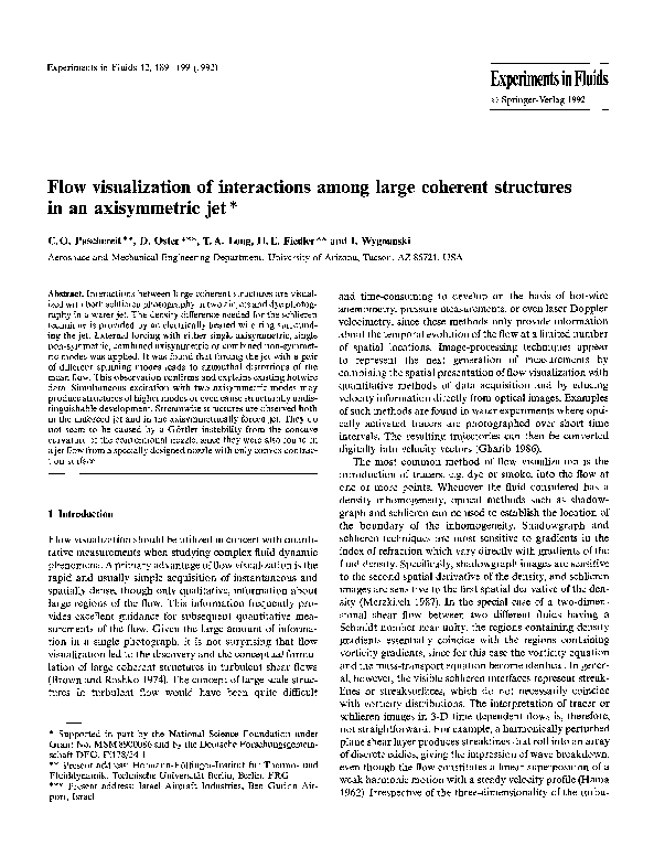
Fig. 3a-d. A side view of a jet forced
by a single mode; a mode m=0 forcing
a snapshot; b mode m= 1 forcing - a
snapshot; c mode m=0 forcing an
ensemble averaged picture; d mode
m = 1 forcing - an ensemble averaged
picture
The dye reservoir was located above the test section of the
jet. It was connected to the nozzle extension with four tubes
which entered the settling chamber of the nozzle extension at
locations spaced 90 ~ apart around the circumference of the
extension. The dye was then injected through a circumferential slit into the nozzle boundary layer by static pressure
from the elevated dye reservoir.
4 Results
4.1 Single mode Jbreing
By forcing a jet column in an axisymmetric mode, the vortex
sheet coinciding with the boundary of the jet is rolled into a
large "ring-vortex" which is also axisymmetric in the mean.
The coherent structures seen in Fig. 3 a were obtained by
forcing the jet with mode 0 and taking a snapshot of the
schlieren image. The photograph represents an instantaneous image of the flow. This picture shows the projection of
the ring vortices and of the interconnecting sheet of vorticity.
The distance between adjacent vortices can be deduced from
the horizontal lines on the photograph which mark intervals
of one nozzle diameter. The longitudinal streaks observed in
Fig. 3 a correspond to the instantaneous convolutions of the
heated sheet of fluid.
The snapshot of the jet forced with mode 1, shown in
Fig. 3 b, is not as sharp as the corresponding snapshot taken
of the jet forced with mode 0. The reduction in contrast, and
therefore in clarity, is attributed to two factors. First, the
incident light in the case of the axisymmetric forcing passes
through regions of similar density gradients twice, once as it
penetrates the ring vortex in the front of the jet, and once as
it leaves the ring vortex in the rear of the jet. For the helically
forced jet, however, the incident light only intersects the core
of a helical vortex filament once as it passes through the jet.
Second, the density gradients generated by the heated wire
degrade in the direction of streaming. Since the image of the
helical mode starts out at approximately half the strength of
the image of the axisymmetric mode, the helical vortex core
is not visible as far downstream as the axisymmetric structures.
Using stroboscopic illumination, ensemble-averaged photographs were taken of the predominant structures in the
forced jet. Figs. 3 c and d represent phase-averaged images of
the jet forced with axisymmetric and helical modes, respeclively. The striations visible in Fig. 3 c indicate that streamwise vortices reside in preferred azimuthal locations under
axisymmetric mode of forcing. The streamwise structures
may have been triggered by slight imperfections in the nozzle
surface, initiating a secondary, azimuthal instability of the
vortex rings (Widnall et al. 1974). Another possibility is that
�194
Experiments in Fluids 12 (1992)
4.2 Combined axisymmetric forcing
Fig. 4a-c. A side view of an axisymmetrically forced air jet; a forced
at the fundamental frequency; b forced at the subharmonic frequency; c combined forcing at the two frequencies
the streamwise structures are remnants of G6rtler instabilities in the concave portion of the contraction. When the jet
is forced with a helical mode, the vortex ring is replaced by
a helical vortex filament (Fig. 3 d). The secondary streamwise
vortices which are expected to be superposed on the primary
helical structure are not as clearly visible in either the snapshot or the ensemble-averaged picture. These secondary vortices might be inclined in different directions across the jet,
they might also rotate or oscillate in the azimuthal direction
and are thus obliterated in the phase-locked, ensemble-averaged photograph.
One may examine the visible effects on the structure of the
jet excited simultaneously with two axisymmetric modes at
different frequencies, a fundamental and its subharmonic. In
Fig. 4 a, the jet is forced with a single frequency corresponding to St = f D/U = 2.3. Three ring vortices are observed at
x/D < 1 which are separated by a distance equivalent to 0.2
diameters of the nozzle. Breakdown to turbulence under
these conditions (Re=13,000) occurs approximately one
diameter downstream of the nozzle. Forcing the jet at half
the frequency (St=l.15; Fig. 4b) while maintaining all
other parameters unchanged elongates both the distance
between adjacent ring vortices and the distance from the
nozzle at which breakdown occurs by a factor of 2, as seen
in Fig. 4a and b. Combined forcing under these circumstances (Stfund = 2.30, Stsu b = 1.15 ; Fig. 4 c) generates eddies
which are similar to the eddies generated by the subharmonic frequency alone (Fig. 4 b). These similarities are not sensitive to the initially imposed amplitude ratio, R = A J A s = 1.0.
Quantitative measurements (Paschereit and Wygnanski 1990)
have also shown that the relative forcing amplitude has only
little effect on the structure of the jet over the range
0.1 _<R _<1.6. The number of ring vortices observed remains
unaltered and the predominant distance between adjacent
vortices remains 0.4 diameters. An interaction between adjacent ring vortices can be seen approximately 0.6 diameters
from the nozzle exit. In addition, the ring vortex at x/D "~ 1.6
is clearly turbulent. Both observations are attributed to forcing the jet with a combination of fundamental and subharmonic axisymmetric modes. Since the three pictures shown
in this figure were not synchronized with the phase of the
forcing, one cannot compare the absolute distances from the
nozzle at which roll-up occurs.
The large coherent structures resulting from axisymmetric forcing of a jet were also examined in water by dye
visualization. Figures 5 a and b are side views of the water jet
with simultaneous forcing of fundamental and subharmonic
modes (Re = 5,000; Stfund = 1.0, Stsu b = 0.5). One may observe
the streakline pattern just before (Fig. 5a) and just after
(Fig. 5 b) a vortex interaction. The first three vortices in both
pictures are laminar. Note in Fig. 5 a that the second vortex,
which is being drawn through the center of the preceding
vortex, has developed large amplitude azimuthal variations.
The azimuthal waviness is also visible on the preceding
vortex buth with smaller amplitude (see also Fig. 6c). As
the second vortex is pulled through the center of the third
(Fig. 5 b), the strain field causes the amplitude of the azimuthal variations to increase drastically while the streamwise extent of the second vortex more than doubles.
The interaction rapidly destabilizes the eddies which become turbulent shortly thereafter. It should be noted that
beyond the region of interaction, the dye marking of the
eddies no longer has a toroidal shape. In addition, Figures
6a c demonstrate that in spite of the axisymmetric forcing,
the preferred structure of the jet further downstream need
�C.O. Paschereit et al.: Flow visualization of interactions among large coherent structures in an axisymmetric jet
195
Fig. 5a and b. A side view of an axisymmetrically forced water jet at two
frequencies; a before vortex interaction;
b after vortex interaction
not be axisymmetric. The jet may develop a helical mode of
either positive or negative sense (Figs. 6 a and b) or the jet
may have no distinguishable mode at all (Fig. 6 c).
Viewing the air jet axially, as shown in Fig. 7, reveals the
existence of streamwise structures in the flow. The dark region in the centers of Figs. 7 a e is due to the hole cut in the
mirror to allow it to sit flush with the nozzle exit. A schlieren
image of the unforced jet photographed at Re= 13,000 is
shown in Fig. 7a. The notable feature in this figure is the
existence of streamwise vortices around the circumference of
the shear layer, which appear as "horse-shoe" shapes, located between the nozzle and the heated wire. These structures
bear a strong resemblance to the azimuthal instability of a
vortex ring (Didden 1979; Glezer 1988). One should remember, however, that the image shown in Fig 7 a corresponds to
an integrated view of the potential core of the jet rather than
a single vortex ring. It was ascertained, by using the purely
convergent nozzle described above, that the azimuthal struc-
ture in an unforced jet need not to be triggered by the
G6rtler instability associated with the concave section of a
conventional contraction. The azimuthal structure is, therefore, a manifestation of a secondary instability of the large
coherent structures in the jet.
Schlieren images of the jet forced at the fundamental
frequency (Stfuna=2.30), and with the combination of the
fundamental and the subharmonic frequencies (Stfuna-- 2.30,
Sts,b= 1.15), are shown in Figs. 7b and c, respectively. The
subharmonic case is indistinguishable from the fundamental
case shown in Fig. 7 b and is thus not presented. When comparing Figures 7 a - c , it is seen that axisymmetric forcing
acts to stabilize the position of the streamwise vortices. Since
the fundamental and subharmonic forcing reveals essentially
identical secondary azimuthal structures, it can be concluded that, in the range of frequencies tested in this experiment,
the streamwise vortices do not depend on the frequency of
forcing. With this in mind, it is not surprising to find that
�196
E x p e r i m e n t s in F l u i d s 12 (1992)
Fig. 6 a - c . T h e e m e r g e n c e of helical
m o d e in the jet despite a x i s y m m e t r i c
forcing; a m = 1 ; b m = -- 1 ; e n o distinct
lower m o d e
�C.O. Paschereit et al.: Flow visualization of interactions among large coherent structures in an axisymmetric jet
197
Fig. 7 a - f . A top view of the air jet; a no forcing; b axisymmetric forcing at the fundamental frequency; e axisymmetric forcing at two
frequencies, a fundamental and a subharmonic; d forcing simultaneously at mode rn1=2 and m2 = - - 1 ; e forcing simultaneously at mode
m 1=2 and rn2 = - 2 ; f contours of u'2 while the jet was simultaneously forced with m= _+2 mode
forcing the jet with a c o m b i n a t i o n of axisymmetric modes, as
in Fig. 7 c, has little or no effect on the azimuthal structure
of the jet, although the amplitude of the structures appears
to have increased with the increased forcing level of the
combined forcing case. One m a y conclude from Figs. 5, 6,
and 7 a - c , that the p r i m a r y vortex structure is d o m i n a t e d by
the s u b h a r m o n i c frequency while the streamwise vortex
structure is stabilized by axisymmetric forcing although it
does not scale with the Strouhal n u m b e r based on nozzle
diameter.
4.3 Azimuthal distortion of the mean flow
Azimuthal distortion of the mean flow can be accomplished
by forcing the jet at a single frequency with a pair of different
spinning modes, m 1 and m 2. The triad resonance conditions
predict that the resulting p e r t u r b a t i o n on the axisymmetric
mean flow will have the form cos [(ml-m2) ~b], where q5 is
the azimuthal angle. Cohen and Wygnanski (1987) calculat-
ed these distortions under inviscid parallel flow conditions
and d e m o n s t r a t e d their existence in an axisymmetric jet.
Long and Petersen (1990) refined this prediction, showing
that the pattern can be rotated at will by changing the phase
between the two forced modes. The azimuthal distortion was
visualized by taking schlieren pictures of r-~b cross sections
of the jet. W h e n the flow was excited with modes m 1--2
and m z = - 1, Figure 7d, the mean flow had the predicted
3 azimuthal lobes. Forcing the jet with m l = - m 2 = 2 ,
Figure 7 e, p r o d u c e d the expected 4 lobe pattern of the mean
flow.
Quantitative measurements by Petersen and Long (1990)
confirm the visual observations (Figs. 7 d and e), suggesting
that the small scale turbulent m o t i o n is primarily contained
within the large azimuthal lobes. The m o d u l a t i o n of b r o a d
b a n d turbulence by the coherent structures in the jet is both
a novel and a technologically significant effect. A sample of
the {u '2} fluctuations measured by Petersen and Long for the
4 lobe case is shown in Fig. 7 f. The plot represents contours
of equal turbulence intensity measured at x/D=2.0. This
�198
Experiments in Fluids 12 (1992)
layer. The two waves intersect at two azimuthal locations,
180 ~ apart because of symmetry, during each cycle of forcing.
The intersecting non-coplanar vortices produce 3-D vorticity fluctuations which lead to the increased turbulence levels
and thus locally increased spreading rates.
5 Conclusions
Fig. 8a and b. A side view of the air jet undergoing model interaction; a ~b=0 (minor axis); b q~=~/2 (major axis)
effect is accentuated by the flow visualization method because the schlieren image produced by the system shown in
Fig. 2 b integrates along the beam of light which, in this case,
coincides with the jet axis.
The effect of modal interaction on the streamwise evolution of the jet is seen in the streamwise views shown in Fig. 8.
In this case the jet was forced with m~ = + 1 and m 2 = - 1 to
produce a cos (2 ~b) distortion. Consequently, the characteristic width of the jet depends on the angle from which it is
viewed. The photographs shown in Figs. 8 a and b represent
views of the jet along minor (q~=qSo) and major (~b=~bo+
n/2) axes of the cos (2q~) distortion, respectively. The large
structures viewed in this manner appear as if they were
triggered by an axisymmetric excitation. These large eddies,
however, are not toroidal and many also appear while the
flow is contracting towards the center (Fig. 8 a) and not only
during divergence (e.g. Fig. 3a). The jet viewed along the
minor axis is narrower at 1 < x/D < 2, and at x/D -~ 2 downstream it is approximately 2 0 - 2 5 % wider along the major
axis than on the minor axis of the distorted flow. One may
also notice that the shear layer spreads into the core of the
jet at a much smaller downstream distance in Fig. 8b as
compared to Fig. 8 a. This effect results from the interaction
of the two helical disturbances of opposite sign in the shear
A thin sheet of locally heated fluid was used in conjunction
with schlieren photography to visualize both large coherent
structures and small scale turbulence in a jet. In unsteady
flows both schlieren and the dye images must be interpreted
carefully, since both methods show streaklines rather than
the interface between the jet and the surrounding fluid.
Nonetheless, both schlieren and dye photographs have led to
an increased understanding of known phenomena, and have
suggested new directions of research.
An instability manifested by an array of streamwise vortices was observed in an unforced jet as well as in an axisymmetrically forced jet. Although the streamwise structures are
affected by the forcing, they did not appear to scale with the
Strouhal number based on the forcing frequency and the
conditions at the nozzle (i.e. St=f D/U). While the streamwise striations observed in the various photographs could be
triggered by a G6rtler instability associated with the concave
curvature of a conventional nozzle design, the latter is probably not the leading mechanism for their appearance.
Streamwise striations were also seen in a flow emerging from
a strictly convex contraction, in which the G6rtler instability
does not exist. This proves that the streamwise vortices observed represent a secondary instability inherent to the perturbed shear layer surrounding the jet column. Exciting the
jet simultaneously with two axisymmetric modes did not
affect the azimuthal structure of the forced flow over the
observed range of Strouhal numbers. The streamwise development of the flow, however, was altered due to interaction
between neighboring vortices.
Mean flow distortion of the jet column resulting from
simultaneous excitation with two different azimuthal modes
at the same frequency was observed by this technique. Since
schlieren images are sensitive to the first derivatives of the
density with respect to space, the azimuthal modulation of
the "small scale turbulence" residing inside the large coherent eddies was also observed. Since the bulk of the small
scale motions in the shear layer were contained inside the
large scales, the mixing process, which depends strongly
on small scale activity, may be significantly manipulated
through control of the large eddies alone.
Acknowledgements
The authors would like to acknowledge the assistance of Professor
Ari Glezer of the Aerospace and Mechanical Engineering Department at the University of Arizona for the loan of the spherical
mirror and the video camera used in the schlieren system. Professor
�C. O. Paschereit et al.: Flow visualization of interactions among large coherent structures in an axisymmetric jet
Glezer also provided assistance in the design of the optical system.
The authors would also like to acknowledge the assistance of Mr.
Eli Horev, Visiting Research Scientist, for the design and construction of the forcing mechanism used for the water jet visualization.
Mr. Horev also assisted in the photography of the dye visualizations.
References
Brown, G. L.; Roshko, A. 1974: On density effects and large structures in turbulent mixing layers. J. Fluid Mech. 64, 775 816
Clough, R. C. 1989: Vortex interactions in an axisymmetric water
jet. University of Arizona (Masters Thesis)
Cohen, J.; Wygnanski, I. J. 1987: The evolution of instabilities in the
axisymmetric jet. Part 2: The flow resulting from the interaction
between two waves. J. Fluid Mech. 176, 221-235
Didden, N. 1979: On the formation of vortex rings: rolling-up and
production of circulation. J. Appl. Math. Phys. (ZAMP) 30, 101116
199
Gharib, M. 1986: Flow velocity measurements by image processing
of optically modulated tracers. AGARD-CP-413, 22
Glezer, A. 1988: The formation of vortex rings. Phys. Fluids 30,
3532-3542
Hama, E R. 1962: Streakline in a perturbed shear flow. Phys. Fluids
5, 644 650
Long, T. A.; Petersen, R. A. 1990: Controlled interactions in a forced
axisymmetric jet. Part 1 : The distortion of the mean flow. (submitted to J. Fluid Mech.)
Merzkirch, W. 1987: Flow visualization, pp. 126-137. London:
Academic Press
Paschereit, C. O.; Wygnanski, I. J. 1990: On instabilities in the
axisymmetric jet: subharmonic resonance. (submitted to AIAA)
Petersen, R. E.; Long, T. A. 1990: Controlled interactions in a forced
axisymmetric jet. Part 2: The modulation of broadband turbulence. (submitted to J. Fluid Mech.)
Widnall, S. E.; Bliss, D. B.; Tsai, C. Y. 1974: The instability of short
waves on a vortex ring. J. Fluid Mech. 66, 35-47
Received July 18, 1991
�
 Berl Oster