Module 3
- 1. Foundations
- 2. • Parts of building are classified into 2 categories • Sub structure- It is the lowest portion of the building which is usually considered to be located below the ground level • Transmit the load of super structure to the soil • Super structure-Portion which is constructed above the sub structure
- 3. • Substructure –Nothing but the foundation which is provided to give stability to the building and to distribute the load coming from super structure. • Subsoil –is weak –the load –transferred to –deep strong strata- by means of long vertical members called piles.
- 5. Purposes of foundation 1. Even distribution of load-Distributes load from superstructure over a large area 2. Reduction of differential settlement-All non uniform load distributed properly on subsoil by foundation ,settlement is minimized. 3. Safety against sliding and overturning- Due to lateral loads. 4. Safety against undermining-Due to flood water or burrowing 5. Firm and level surface-provide for the construction of superstructure
- 6. Bearing capacity of soils • The maximum load per unit area which the soil or rock can carry without yielding or displacement is termed as the bearing capacity of soils. (The supporting power of soil without any failure is called bearing capacity.) • Soil properties like shear strength, density, permeability etc., affect the bearing capacity of soil. • Selection of suitable foundation is an important task • Type, depth, shape and size of the foundation are to be determined. • Load from the structure are finally transmitted to soil. • So it is important to study strength and behavior of soil
- 7. Important in design of foundations • It depends on :- 1. Properties of soil like cohesion ,angle of friction 2. Allowable and differential settlement 3. Position of water table 4. Physical features of foundation like type ,size shape and rigidity 5. Depth of strong strata.
- 8. • Ultimate bearing capacity is the theoretical maximum pressure which can be supported without failure • Allowable bearing capacity is the ultimate bearing capacity divided by a factor of safety. Factor of safety adopted is 2-5
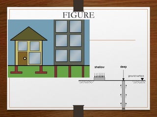
- 9. TYPES OF FOUNDATIONS Divided into two categories Shallow foundation -When the depth of the foundation is less than or equal to the width. • Open foundation -normally constructed by way of open excavations Deep foundation -have depth more than width
- 10. Shallow foundation/spread foundation • Placed immediately below the part of the superstructure supported by it • Footing –often used along with foundation. • Foundation unit constructed in masonry or concrete under the base of the column or wall. • Have one or more footings
- 11. FIGURE
- 12. Various types of shallow foundations 1) Isolated or column footing 2) Wall or strip footing 3) Combined footing 4) Continuous footing 5) Cantilever footing 6) Inverted arch footing 7) Grillage foundation 8) Raft or mat foundation
- 13. 1. Isolated or column footing • Provided for column to transfer the load safely to the soil beneath. • When the load on the column is less a spread is given under the column • This is called isolated footing. • Simple footing-adopted for light load • Stepped or sloped footing-adopted for medium and heavy column loads.
- 15. 2.Wall or strip footing • Provided for through out the length of continuous structure. • Normally adopted for load bearing walls. • Simple or stepped
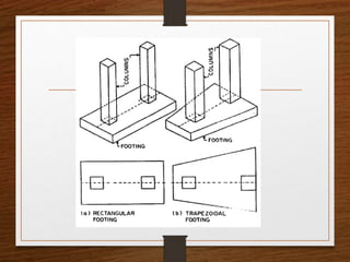
- 17. 3. Combined footing • Footing is constructed for two or more columns . • Shape-rectangular or trapezoidal • Centroid of the footing area coincides with centre of gravity of the loads on footing. • Adopted for lift well column, water tank supporting column, bus shelter supporting columns. • Adopted incase of two individual footing overlapping, bearing capacity of soil less i.e. require more area, when footing constructed near boundary.
- 19. 4.Continuous footing • Single continuous reinforced concrete slab is provided as foundation for three or more columns in a row. • It is more suitable to prevent the differential settlement in the structure and for safety against earthquake
- 21. 5. Strap/ Cantilever footing • Consists of an eccentric footing for the exterior column and a concentric column for the interior column. • A strap or a cantilever beam connects them. • Used when it is impossible to place a footing directly below the column because of limitations of boundary of site or eccentric loading conditions
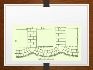
- 23. 6.Inverted arch footing • Used to transmit load above an opening to the supporting walls • Constructed between the two walls at the base • The end columns are to be designed to resist the outward pressure caused by arch action. • Commonly used for bridge piers, reservoirs tanks and support for drainage work
- 25. 8.Raft or mat foundation • Combined footing which covers entire area beneath the structure. • Consists of a single continuous reinforced concrete slab or inverted beam and slab construction. • These are adopted when 1. Load is heavy and bearing capacity is less. 2. Isolated footing of each column requires large area, 3. In highly compressible soils 4. To counteract the effect of hydrostatic pressure
- 27. Deep foundations • Very large depth compared to width • Various types Pile foundation Well foundation
- 28. Pile foundation • Normally installed by driving by hammer or any other suitable method • Usually placed in groups to provide foundation for structure • Pile group may be subjected to vertical and horizontal load or combination of both • Classified according to the material composition, installation method, ground effect and their function as a foundation
- 29. Classification based on their function as a foundation • End bearing pile-when the top soil is soft or too weak to support the super structure, piles are used to transmit the load to the underlying bed rock • Friction pile-if the bed rock is not existing at a suitable depth below the ground surface, the load is transferred through the friction along the pile shaft such piles are called friction piles
- 31. • Compaction piles-Piles are used to densify loose soils • Sheet piles-used to retain the earth or to reduce seepage flow of water in hydraulic structures.(made up of steel timber or concrete) • Batter piles-inclined piles to resist the inclined forces, constructed at ports harbors and oat jetties • Anchor piles-provide anchorage against pulling or pushing forces due to retaining earth
- 32. Under reamed pile • It is a type of bored cat in situ concrete pile with large base • The enlarged base is termed as bulb or under ream • Have one two or more bulb
- 34. DRILLED PIERS • They are structural members of relatively large diameter massive structures constructed of concrete placed in pre- excavated hole • Called as bored piles, large diameter piers, foundation piers
- 36. BRICK MASONARY
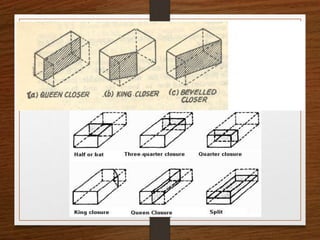
- 37. Masonry – defined as the construction of building units like bricks, stones or concrete blocks bonded together with mortar Brick masonry – brick units bonded togther with mortar Strecher - A brick laid with its length parallel to the direction of wall Header – A brick laid with its length perpendicular to the direction of wall Course – horizontal layer of brick or stone Closer – portion of a brick, either cut from a regular brick or manufactured according to required shape, helps in preventing the joint overlapping in successive courses, may be of various types
- 38. King closer – portion of brick, cut such that the width of one end is half that of a full brick, obtained by cutting a triangular piece between the center of one end and the other Queen closer – obtained by cutting a brick into two equal half lengthwise, have half the width of the full brick Bat – portion of brick cut along the width
- 40. Bonds – method of arranging the bricks in course so that individual bricks are locked together Various types of bonds are distinguished by their elevation or face appearance Improper arrangements will result in continuous vertical joints, their by reduction in strength and stability
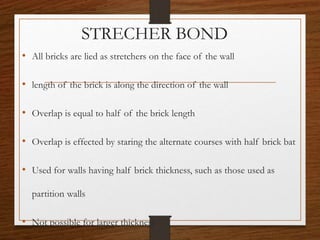
- 41. STRECHER BOND • All bricks are lied as stretchers on the face of the wall • length of the brick is along the direction of the wall • Overlap is equal to half of the brick length • Overlap is effected by staring the alternate courses with half brick bat • Used for walls having half brick thickness, such as those used as partition walls • Not possible for larger thickness
- 42. STRETCHER BOND
- 43. HEADER BONDS All the bricks are laid as headers on faces of walls The width of the brick is along the direction of the wall Can be made only when thickness of the wall is equal to one brick Suitable for partition walls Also used for curved brick work
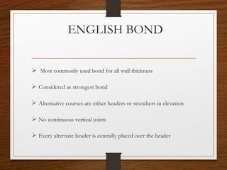
- 45. ENGLISH BOND Most commonly used bond for all wall thickness Considered as strongest bond Alternative courses are either headers or stretchers in elevation No continuous vertical joints Every alternate header is centrally placed over the header
- 47. POSITIONING OF DOORS & WINDOWS KTU syllabus based
- 48. POSITION OF DOORS AND WINDOWS• Number of doors and windows should be kept minimum • The location & size of building should be based on functional requirement • For good ventilation and air circulation doors should be located in opposite walls facing each other. • Doors should be placed at corner of room. • Location, size and number of windows are decided considering various factors, like, desired daylight, desired vision of outside, privacy, natural ventilation etc. • For good ventilation, windows should be given in opposite walls whenever possible • For max daylight, windows should be located in northern side • Sill height of windows should be located at a height of 0.75 to 1m from floor. In case of bathrooms etc. it is located at a higher level(privacy).
- 49. 1. Aesthetics• The placement of your doors will directly affect the aesthetics of your home, and can completely change the look and feel of any part of your home. • handing and swing direction, as both of these factors will change the way space can be used in the room when the door is open. • The position of your front door will define the entire look of the facade of your home, just as the positioning (and size) of your home's rear doors will affect the way they open onto your back yard.
- 50. 2. Positioning and security • Good design will place the hinges of your front door on the inside of your home, protecting them from being tampered with from the outside. • Depending on how your home's designed, you may also need to consider how visible your front door is from the street - in some cases, having the door visible from the street or from a neighbour's yard can serve as a deterrent to would-be thieves.
- 51. 3. Clearance and space • You will need an area that has enough clearance room for a door to open and enough space to get around it if it’s sitting at 90 degrees to the wall. The frame will need to have enough space for the door, but also a little clearance on all sides for swing room. Think carefully about which way the door is to be handed, having the handle on the wrong side could cause damage to the walls and paintwork. • Doors should be positioned so that they don't interfere with each other, or open into hallways or accessways
- 52. 4. Door position, ventilation and airflow • Another important factor to think about is the airflow through your house. Aligning doors and windows through rooms and hallways can create a wind tunnel effect when the doors are open. While this is very useful for effective wind ventilation, it may also be disruptive or uncomfortable if it's too breezy. By staggering doors, even slightly, you can break up the tunnel’s flow and reduce the speed of a draught. This can also circulate the air better, encouraging it to circulate throughout the room or house instead of directly through it. • Doors that open to the outside should also open inwards if facing the windier side of the house. A door opening outwards in a strong gale can put great strain on the hinges, and may even loosen the door from the frame.
- 53. OPEN SPACE REQUIREMENTS • As per KBR 1999( Kerala building rules) • Exterior open spaces Every building up to 10m height shall have 1. Minimum Front Yard Of 3m Depth 2. Minimum Back Yard Of 2m Depth 3. 1.2m And Not Less Than 1 M In Sides
- 54. Buildings above 10m height • Front open space – 3m + 0.5m per every additional 3m above 10m • Rear open space – 2m + 0.5m per every additional 3m above 10m • Side open space – 1.2m/1m + 0.5m per every additional 3m above 10m
- 55. For buildings above 4 storeys • A minimum of 5m should be given in any one side contiguous to front side • Plot are less than 125sq.m. • Front yard – 1.8m • Rear yard – 1 m • Side yard 0.9m in one side & 0.6m in other side For buildings in small plots
- 56. INTERIOR OPEN SPACES • Any habitable room not abutting on front, rear or side open spaces, shall abut on an interior open space with a minimum width of 2.4m • If the total height of the residential building is less than 7m, then the interior open space shall have 1.5m width
- 57. SIZE OF ROOMS • From the view of health and ventilation NBC specifies the minimum sizes for the habitable rooms in houses and apartments as follows Habitable Room • Minimum area of 9.5m2 , with minimum width 2.4m, when there is only one room • If there 2 rooms, minimum area for one room is 9.5m2 and of other room is 7.5m2, with minimum width of 2.4m
- 58. SIZE OF ROOMS • Kitchen • For kitchen cum store, minimum area is 5.5m2 with minimum width 1.8m • For kitchen with separate store, minimum area is 4.5m2 and width 1.8m • For kitchen cum dining room, minimum area 9.5m2, and width 2.4m
- 59. SIZE OF ROOMS • Bathrooms & Water closet • Bathrooms minimum size – 1.5m x 1.2m & area 1.8m2 • Water closet, minimum area 1.1m2 • Bathroom combined with water closet- Minimum area = 2.8m2 • Minimum Width 1.2m
- 60. SIZE OF ROOMS • Mezzanine floor Minimum area of mezzanine floor if used as living room is 9.5 m2 and shall not exceed one third of the plinth area of the building
- 63. ROOF • A roof is the uppermost part of a building whose main function is to enclose space and to protect the same from the effects of whether elements such as rain, wind, sun, heat and snow. • Requirements of an ideal roof Strength and stability Weather resistance Heat insulation Sound insulation Fire resistance Waterproof & good drainage arrangement. 63
- 64. TERMS USED • Span: clear distance between the supports of roof • Rise: vertical distance between top of the ridge and wall plate • Pitch: It is the slope of the roof. It is obtained as the ratio of rise to span. • Ridge: Apex line of sloping roof. • Eaves: Lower edge of inclined roof surface. • Hip: Ridge formed by joining two sloping surfaces, external angle is greater than 180. • Valley: Reverse of hip. Formed by the intersection of two roof surfaces, making an external angle less than 180. • Principal rafter: This is the inclined member running from the ridge to the eaves. 64
- 65. 65
- 66. 66
- 67. 67 • Purlins: These are horizontal wooden or steel members, used to support roofing material of a roof. Purlins are supported on trusses or walls. • Wall plates: These are long wooden members, which are provided on the top of stone or brick wall, for the purpose of fixing the feet of principal rafters. • Battens: These are thin strips of wood, called scantlings, which are nailed to the rafters for lying roof materials above. • Cleats: These are short sections of wood or steel, which are fixed on the principal rafters of trusses to support the Purlins. • Truss: A roof truss is a framework, usually of well-formed triangles, designed to support the roof covering or ceiling over rooms.
- 68. 68
- 69. 69
- 70. 70 • The roofs should be well designed and constructed to meet the requirements of different climates and the covering materials available • The roofs may be classified as follows: 1) Pitched or sloping roofs 2) Flat roofs 3) Shell roofs 4) Domes DIFFERENT TYPES OF ROOFS
- 71. 71 • Pitched roofs or sloping roofs are very suitable in coastal regions where rainfall is heavy and flat roofs are suitable in plains where rainfall is low and temperatures are high.
- 72. PITCHED ROOF OR SLOPING ROOF Different types of pitched roofs are, 1. Lean to roof 2. Couple roof 3. Couple close roof 4. Collar beam roof 5. Collar and tie roof 6. King post truss 7. Queen post truss 8. Mansard truss 9. Steel trusses 72
- 73. Lean to roof • Simplest type of pitched roof. • Consists of rafters that slope in one direction only. • Generally, it is used to cover the verandah of a building and projects from the main wall of building. • It is suitable for spans up to 2.5 m. 73
- 74. 74
- 75. Couple roof • In this type of roof, each couple or pair of common rafters is made to slope upwards from the opposite walls and they are supported at the upper ends by ridge piece or ridge board in the middle. 75
- 76. 76 • The lower ends of the common rafters are fixed to the wall plates embedded in the masonry on the top of the walls. • The use of this form of roof is not favoured as it has a tendency to spread at the feet and thrust out the walls. • Therefore adopted only for a height of 3.5 m.
- 77. Couple close roof• Similar to a couple roof except that the legs of common rafters are closed by a horizontal tie known as tie beam. • The tie beam is connected at the feet of common rafters to check their tendency of spreading outwards and hence saves the walls from the danger of overturning. • Under normal conditions this type of roof can be used for a maximum span of 4.5 m. • However, for increased spans or greater loads the rafters have a tendency to sag in the middle. 77
- 78. Collar beam roof • Used for spans between 4 and 5.5 m. • A collar of same width as rafter is fixed to every pair of rafters and is attached at a height of half to one-third of the vertical height between the wall and ridge. 78
- 79. 79 • The collar is dovetailed with the rafter and the bolts can be used for additional safety. • Desirable to place collar as low as possible to provide maximum strength to the roof.
- 80. King post truss• For spans greater than 4.8 m, when no intermediate supporting walls for the purlins are available, framed structures known as trusses are used. • Spacing between trusses depends on the load coming on the roof, material of the truss, span and location of cross walls. 80
- 81. 81 • In king post truss, the central vertical post called as king post provide support for tie beam. • The inclined members are known as struts and are used to prevent the principal rafters from bending at the centre. • King post truss can be used economically for spans 5-8 m.
- 82. 82 • Joint between the king post and the tie beam is an ordinary mortise and tenon joint. • Bridle joint is provided to connect the principal rafter with the tie beam.
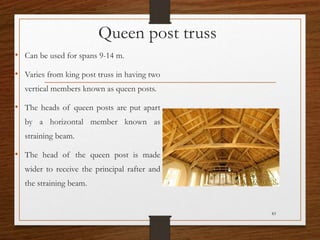
- 83. Queen post truss • Can be used for spans 9-14 m. • Varies from king post truss in having two vertical members known as queen posts. • The heads of queen posts are put apart by a horizontal member known as straining beam. • The head of the queen post is made wider to receive the principal rafter and the straining beam. 83
- 84. Mansard trusses • Combination of king post truss and queen post truss. • Upper portion has the shape of king post truss and lower portion resembles a queen post truss. • The truss has two pitches. 84
- 85. 85 • The upper pitch varies from 30 to 40 degree and the lower pitch varies from 60 to 70 degree. • This type of truss is economical and in the span an extra room may be provided. • This type of truss is now rarely used because of its ugly appearance. • Construction of various joints is similar to that of the king post trusses.
- 86. Steel trusses• Their use has become economical for spans greater than 12 m. • Various standard sizes and shapes of rolled steel are available for the fabrication of steel trusses. • When large column free areas are required. 86
- 87. 87 • T sections are best suited for use as principal rafters, where as angle iron or channel section is used as struts. • The members of a truss are joined by rivets or by welding plates known as gusset plates.
- 88. 88 The relative advantage of steel trusses over timber sloping trusses are; 1. Steel trusses forming the roof are light in weight and can be fabricated in different shapes and sizes. Suits the structural as well as architectural requirements. 2. Steel sections made of mild steel sections are free from the attack of white ants and dry rot. 3. These trusses are fire resistant and can be used where fireproof construction is desired. 4. Much stronger than timber trusses and they are usually strong in tension and compression.
- 89. 89 • Steel trusses are used for structures requiring large spans such as industrial buildings, large sheds, assembly halls, hangers and auditoriums. Timber trusses can only be used up to minimum span of 14 m or so, whereas there is no span restriction in case of steel trusses. • Sections forming a steel truss can be easily machined and shaped in the workshop and subsequently packed and transported to site for assembling. There is no wastage in cutting. • Erection of steel trusses from the rolled sections is very easy, rapid and economical.
- 90. FLAT ROOFS • A roof which is approximately flat is called flat roof. • It may be constructed in RCC, flagstone supported on rolled steel joist, bricks, concrete or tiled arches. • Flat roofs are suitable in plains where rainfall is low and temperatures are high. 90
- 91. Advantages of flat roof: • Can be used as a terrace for playing or sleeping or for other domestic purposes. • Construction and maintenance is simpler. • Provides better architectural appearance to the building. • Easier to make fire resistant. • Good insulating properties. • Avoids need for false ceiling. • Construction work of upper floors can be readily taken. • Pitched roofs need more area of roofing material than flat roofs. 91
- 92. Disadvantages of flat roof • Cannot be used for long spans without using columns and beams. • Not suitable for heavy rainfall areas. • Initial cost is more. • Due to greater variations in the temperature cracks sometimes develop on surfaces of the roof, which is difficult to repair. • Speed of construction is slower than that of a pitched roof. • If proper slope is not provided on the roof to drain off rainwater , pockets of water are formed on the surface of the roof, which leads to leakage in the roof. 92
- 93. Reinforced concrete slab roof • An average of 10-13 cm thick LC terracing with some waterproofing compound is provided over the RCC slab to make the roof leak proof. • At the junctions with walls, the lime terracing is taken inside the wall for 10-15 cm depth and round shape such that water may not accumulate. • The lime terracing is provided with a slope(1 in 60 or 1 in 100) to drain off the rainwater easily from the roof. 93
- 94. 94
- 95. SHELL ROOF • Shell roofs are very useful for covering large structures, e.g., assembly halls, recreation centers, libraries, theaters and factories. • Very less quantity of materials are required to build up a shell roof compared to other conventional methods of roofing for same span. 95
- 96. 96 • The design of the shell is made as thin as practical requirements will allow, such that the dead load is decreased and the shell act as a membrane free from large bending stresses. • Common types of shell roof are as follows: 1. North light shell roof is used mostly in factories, workshops and places where good daylight is desired.
- 97. 97 2. If good day lighting is not a requirement, long cylindrical shells with feather edge beams may be useful. 3. Double curved shells are structurally more efficient than single curved shells, but it presents difficulties in preparing the centering for it.
- 98. DOMES • A dome is a special type of shell roof of semi spherical or semi elliptical shape. • Mainly divided into two: 1. Smooth shell domes 2. Ribbed domes • Smooth shell domes may be divided into: 1. Domes with shells of uniform thickness 2. Domes with shells of uniformly varying thickness 98
- 99. 99 • Smooth shell domes are constructed by brick, stone, concrete or tile. • Ribbed domes may be built in steel, concrete or wood.
- 100. Selecting a right roofing There are many things to take into account when selecting a new roof system. These includes; 1.Pitch 2.Cost 3.Durability 4.Aesthetics 5.Architectural style 6.Types of structure you are covering
- 101. 1. PITCH It is the angle of the roof`s incline, measured in inches per foot Eg; a 4 in 12 pitched roof means that for every 12 inches horizontal run there are 4 inches of rise in height PITCHRISE RUN
- 102. 2. COST Cost on a new roof depends mainly on 2 factors - i.e.; material cost and labor cost E.g.; roofing shingles come with a variety of warranties 25year, 30year and lifetime. But labor cost applied is same. Because of this it may actually be less expensive over the life span of the roof to install a more durable product.
- 103. 3. DURABILITY - It is a key factor in maintenance and cost. - Roofing that is easily damaged ,may need to be repaired frequently or possibly replaced - Be sure to look at the warranty of various roofing materials, as it is an indication of how long your roof will cost
- 104. 4. Aesthetics - Aesthetics are something to consider when selecting a new roof. - Because the roofing area may be up to 50% of the exposed exterior of your home ,you should select roofing that coordinates with your siding and will provide a timeless look
- 105. 5, ARCHITECTURAL STYLE IT IS SOMETHING THAT IS NOT FREQUENTLY CONSIDERED WHEN WORKING ON A BUDGET , HOWEVER TO DO THE JOB RIGHT, YOU SHOULD SELECT A ROOFING MATERIAL THAT FITS WITH STYLE OF YOUR HOME e.g.; wood shakes on a contemporary style home may not achieve the look and feel you desire
- 106. ROOFING MATERIALS WOOD SHINGLES AND SHAKES
- 107. Terms Thatch is roofing made of plant stalks in overlapping layers Wheat straw, widely used in England, France and other parts of Europe Seagrass, used in coastal areas where there are estuaries such as Scotland. Has a longer life than straw. Claimed to have a life in excess of 60 years. Rye straw, commonly used in a barn. Raffia palm leaves:A well organised raffia palm leaves is mainly used as roof houses in Nigeria especially among the Igbos. Rice straw, commonly used in Eastern Asia. Water reed, commonly used in Ireland for Thatching.
- 108. •MODULE 6 BASIC INFRASTRUCTURE AND SERVICES Basic infrastructure and services - Elevators, escalators, ramps, air conditioning, sound proofing (Civil engineering aspects only) Towers, Chimneys, Water tanks (brief discussion only).
- 109. Elevator (Lift) Escalator Ramp Air conditioning Sound proofing
- 110. RAMP
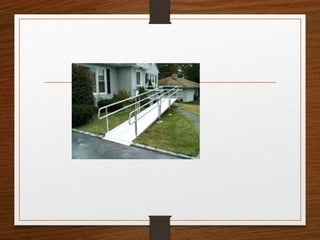
- 112. • They are sloping surfaces used to provide an easy connection between floors • They are especially used when large number of people or vehicles have to be moved from floor to floor • They are usually provided at places such as garages, railway stations, stadium, town halls, office buildings and exhibition halls • Sometimes, they are provided in special purpose buildings such as schools for physically handicapped children
- 114. • They should be constructed with non slippery surface • They are given a slope of 15% • But a slope of 10% is usually preferred • The space required for ramp is more • The ramp need not be straight for the whole distance • Ramp can be curved, zigzagged or spiral
- 117. • Level landings, with a length of at least 1.1m in the direction of travel should be provided at the door openings and where ramps change slope or direction abruptly • Landing should be at least as wide as ramp • Ramps and landings should be designed for a live load of at least 21.2 kg/cm2 • Minimum width of pedestrian ramp is 75 cm for heights between landings not exceeding 3.6 m • Powered ramps, or moving walks, carrying standing passengers may operate on slopes up to 8˚ at speeds up to 60m/min and slopes up to 15˚ at speeds up to 47 m/min
- 119. ESCALATOR
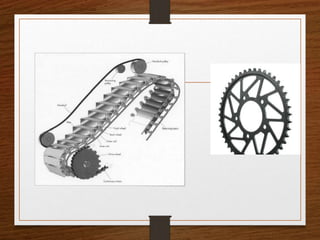
- 120. • They are powered stairs • They are used when large number of people are required to move from floor to floor • These stairs have continuous operation without the need of operators • They have large capacity with low power consumption • The escalators are in the form of an inclined bridge spanning between the floors • Components of escalator: 1. A steel trussed frame work 2. Hand rail 3. Endless belt with steps
- 122. • At the upper end of an escalator there is a pair of motor driven sprocket wheels and a worm gear driving machine • At the lower end there is a matching pair of sprocket wheel • Two precision made roller chains travel over the sprockets pulling the endless belt of steps • Escalators are reversible in direction • They are generally operated at a speed of 30 or 40 m/min • Slope of stairs is standardized at 30˚ • For a given speed of travel, width of step determines the capacity of powered stairs
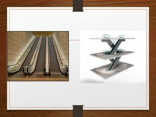
- 124. • Escalators should be installed were traffic is heaviest and where it is convenient for passengers • In the design of a new building, adequate space should be allotted for powered stairs • Structural framing should be made adequately to support them • Escalators are generally installed in pairs • One of them is used for carrying up going traffic • Other one used for carrying traffic moving down • Arrangement of escalators in each story can be either parallel or criss cross • Criss cross arrangement is more compact
- 127. • Criss cross arrangement is preferred over parallel arrangement • Because, it reduces walking distance between stairs at various floors to a minimum Number of floors Speed 4-5 0.5-0.75 m/s 6-12 0.75-1.5 m/s 13-20 above1.5 m/s
- 128. Elevator
- 129. • They are used in building having more than 4 storeys • Used for providing vertical transportation of passengers or freight • 2 types of lift: 1. Electric traction elevators 2. Hydraulic elevators
- 130. Hydraulic elevators • They are generally used for low rise freight service which rises up to 6 storeys • They may also be used for low rise passenger service
- 131. Electric traction elevators • They are used exclusively in tall buildings • Components: 1. Car or cab 2. Hoist wire rope 3. Driving machine control equipment 4. Counterweight 5. Hoistway rails 6. Penthouse 7. pit
- 132. Classification – Based on purpose Passenger lift Designed for the transportation of passengers Hospital lift: Installed in hospitals Designed to accommodate one number of bed or stretcher along its depth minimum of 3 attenders lift operator Goods lift: For the transportation of goods Also carry a lift attendant or other persons necessary for loading and unloading of goods
- 133. Service lift A passenger cum goods lift Used to carry goods along with people Fireman's lift It has the following standards Lift car area not less than 1.44 m2 Minimum capacity 544 kg Doors should have automatic operation Minimum fire resistance of 1 hour
- 134. • Car is the load carrying element of the elevator • A cage of light metal is supported on a structural frame, to the top of which the wire ropes are attached • The ropes raise and lower the car in the shaft • They pass over a grooved, motor driven sheave and are fastened to the counter weights • The paths of both the counter weight and car controlled by separate sets of T shaped guide rails • Control and operating machinery may be located in a penthouse above the shaft or in the basement • Safety springs or buffers are placed in the pit, to bring the car or counterweight to a safe stop
- 135. • For elevators serving more than 3 floors, means should be provided for venting smoke and hot gases from the hoist ways to the outer air in case of fire • Vent may be located in the enclosure just below the uppermost floor, with direct openings to the outside or with non combustible duct connections to outside • Vent area should be at least 35% of the hoistway cross sectional area
- 136. Design considerations Key considerations that affect elevator system design are: 1. Number of floors to be served 2. Floor to floor distance 3. Population of each floor 4. Location of building 5. Specialist services within the building 6. Type of building occupancy 7. Maximum peak demand in passenger per 5 minute period
- 137. Design parameters There are numerous parameters which can be used to judge elevator system performance The principle one is based on quality of service and quantity of service Quality of service It is related to time interval a passenger has to wait It is the expected interval between the arrival of elevators in the main floor For a large building, the quality of service can be categorized as: 1. Average time interval 20-25 seconds - excellent 2. Average time interval 35-40 seconds - fair 3. Average time interval 45 seconds – poor 4. Average time interval over 45 seconds – unsatisfactory
- 138. Population Total building population and its future projections are required for design Probable population density may be obtained from building owner In the absence of other data, an average of 1 person per 5m2 is assumed
- 139. Location of elevators Most efficient method of locating elevators to serve an individual building is to group them together A group has a lower average interval between car arrivals than a single elevator Groups should be located: 1. For easy access to and from the main building entrance 2. Centrally for general ease of passenger journey If a building has areas which give long distance to the central group elevator, then it may be efficient to provide an additional elevator for local areas
- 140. AIR CONDITIONING
- 141. • It is the process of treating air so as to control simultaneously its temperature, humidity, purity and distribution to meet the requirements of the conditioned space, such as comfort and health of human beings and other needs of the situation
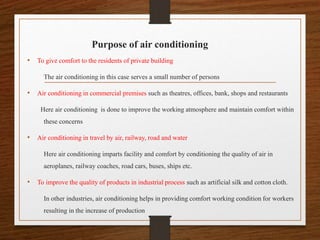
- 142. Purpose of air conditioning • To give comfort to the residents of private building The air conditioning in this case serves a small number of persons • Air conditioning in commercial premises such as theatres, offices, bank, shops and restaurants Here air conditioning is done to improve the working atmosphere and maintain comfort within these concerns • Air conditioning in travel by air, railway, road and water Here air conditioning imparts facility and comfort by conditioning the quality of air in aeroplanes, railway coaches, road cars, buses, ships etc. • To improve the quality of products in industrial process such as artificial silk and cotton cloth. In other industries, air conditioning helps in providing comfort working condition for workers resulting in the increase of production
- 143. Classification Based on function Comfort air conditioning Air inside room are created to give maximum human comfort Industrial air conditioning Atmospheric conditions are created, controlled and maintained suitable for material processing, manufacturing and storage etc. rather than comfort
- 144. Based on air conditioning process Summer air conditioning During summer temperature outside is higher Cycle of air conditioning operation involve: air cooling, dehumidifying, air distribution & air cleaning Winter air conditioning During winter temperature outside is lower Cycle of air conditioning operation involve: air heating, humidifying, air distribution & air cleaning Composite air conditioning It requires to provided for whole year irrespective of outside temperature Cycle of operation involves humidifying together with air distribution and air cleaning
- 145. Steps Involved 1. Sucking air through a filtering media 2. Cooling it in summer or heating it in winter 3. Dehumidification if it is to be cooled, or humidifying, if it is to be heated 4. Forcing it into the room for proper circulation 5. Used air is collected through an exhaust and mixed with some outside fresh air and sucked again through the filtering medium, thus completing the cycle
- 146. Principle of comfort air conditioning Principle of air conditioning involve proper control of temperature, humidity and air velocity 1. Temperature control: Comfortable zone is the temperature range suitable for majority of the people The comfortable zone are different for summer and winter due to the clothing worn in these two seasons The effective temperature zone for summer is 20-23˚C The effective temperature zone for winter is 18-22˚C A temperature of is 21-25˚C required for comfort conditions regardless of the out size temperature
- 147. 2. Air velocity control: • Air velocity control is an important factor • The increase in velocity results in the decrease of inside effective temperature below the outside temperature • Hence, velocity of air is generally taken as 6-9m/s, which is relatively considered as stiff air 3. Humidity control: • Dry air imparts great strain for human body • Due to this reason moisture is added to the heated air in case of winter air conditioning
- 148. • Moisture is extracted from cool air in case of summer air conditioning • Average value of relative humidity between 40% and 60% is considered desirable • During summer season 40-50% is comfortable • For winter 50-60% is suggested
- 149. Systems of air conditioning Depending on the location of air conditioning equipment, the system of air conditioning is classified as follow: 1. Central system 2. Self contained or unit system 3. Semi contained or unitary central system 4. Combined system The choice of a particular type of air conditioning system depends upon several factors: 1. Size of structure 2. Method of heating 3. Volume and type of air conditioning unit 4. Period of year for which air conditioning is required etc.
- 150. 1. Central system In this system all the equipment's pertaining to the air conditioning are installed in a central place Then the conditioned air is distributed to all the rooms by ducts In this system maintenance is easy and requires less space for its installation It is economical as compared to provision of separate units of air conditioning for every room However, it requires ducts of large size and they occupy more space
- 151. 2. Self contained or unit system • In this system, special portable attractive cabinets which fit in with the decorations of modern rooms are placed inside the room near ceiling or enclosures • The conditioned air is then directly thrown into room without the help of any ducts
- 152. 3. Semi contained or unitary central system In this system, every room is provided with an air conditioning unit • The room unit obtain its supply from central system • Such a system results in smaller size of ducts In another form of this system, the conditioned air is supplied from a central unit • But heating or cooling may take place in the room itself
- 153. 4. Combined system • This system may consist of: 1. Central and self contained system 2. Central and semi contained system 3. Self contained and semi contained system
- 154. Water tank
- 155. Used to store water for daily requirements It has to be ensured that concrete does not crack on its water surface Cracking is mainly caused due to free expansion and contraction of concrete due to temperature and swelling due to moisture effects
- 156. Classification: Based on placement of tank 1. Tanks resting on ground 2. Elevated tanks 3. Underground tank Based on shape: 1. Circular tank – Used for bigger capacities 2. Rectangular tank- Used for smaller capacities Longer side should not be greater than 2 times smaller side
- 157. 3. Spherical tank- Water pressure is evenly distributed within tank Requires less reinforcement Less surface area and hence less material is needed 4. Intze tank- Constructed to reduce project cost Lower dome in this resists horizontal thrust 5. Circular tanks with conical bottom
- 158. Based on placement of tank Elevated water tank Underground water tank Tanks resting on ground
- 159. Circular tank Intze tankSpherical tank
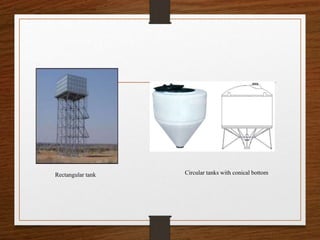
- 160. Rectangular tank Circular tanks with conical bottom
- 161. Concrete water tank Concrete tanks are most commonly used Imperviousness of concrete is very important Imperviousness depends on water cement ratio As water cement ratio increases, permeability increases
- 162. To achieve Imperviousness the following thinks are done: 1. Water cement ratio should be kept as minimum as possible Without affecting the workability of concrete 2. Efficient compaction using vibration 3. A cement content of more than 330 kg/m3 but less than 230 kg/m3 4. A concrete mix of not less than M20 grade is normally used
- 163. 5. Correct placement of reinforcement and use of small size bars Small size bar give better resistance against cracking 6. Care should be taken to avoid segregation and honey combing of concrete at joints to avoid leakages 7. A minimum cover of 25mm or diameter of the main bar which ever is greater is provided for normal conditions In the presence of sea water cover may be increased by 12 mm
- 164. Honey combing of concrete Segregation
- 165. TOWER
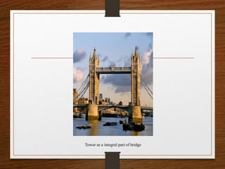
- 166. Tower as a integral part of bridge
- 167. Clock tower Transmission tower Telecommunication tower
- 168. Telecommunication tower Types of communication tower: 1. Based on structural action 2. Based on cross section of tower 3. Based on type of material sections 4. Based on placement of tower 5. Based on number of segments
- 169. Based on structural action A. self supporting B. guide towers C. Monopole towers
- 170. self supporting
- 171. Transmission tower
- 173. syllabus • Concept of intelligent buildings.
- 174. • Reach of Technology • Artificial intelligence & smart programs • Building industry • Intelligent & green buildings
- 175. • An intelligent building is in essence one that integrates various systems ( such as lighting, heating, air conditioning, voice and data communication and other building functions ) to effectively manage resources in a coordinate mode to maximize occupant performance, investment and operating cost, savings and flexibility – Rnee Vedamuthu, facility member school of Architecture & Planning, Anna University Chennai • Intelligent building is one which the building fabric, space, services and information system can respond in an efficient manner to the initial and changing demand of the owner, the occupier and be in harmony with the environment – Agith G, Editor –in – Chife, The Master Builder
- 177. • Intelligent building system concept system – cost of construction is not the true cost of building • Must include the operational and the maintenance cost through out the its life span. • I.B optimizes the cost over all these years by optimizing energy use through automated control, communication and management system • Following features are accepted in a new intelligent building
- 178. 1) High-speed fiber optic communication network for data, video and BAS (Building Administrative System) 2) Flexible HVAC system with modular distribution and 100% outdoor air capability to take advantage of free cooling as well as to allow flushing of the building to dilute volatile off-gassing contaminants 3) Individually controlled HVAC terminal units allowing occupant control flexibility through Intelligent Terminals Controllers at each workstation 4) Advanced integrated Energy Management & Control System (EMCS) utilizing direct digital control technology for HVAC, Lighting, Fire Alarm and other building support systems
- 179. 5) Dedicated circuit power distribution network complete with Uninterrupted Power Supply (UPS) units. 6) Maximum transparency and communication capabilities between subsystems. 7) Electrical design features tailored to Intelligent Building. 8) Generous stand by power generation 9) High efficiency filtration, energy recuperation and/or thermal storage features to improve indoor air quality and energy consumption performance. 10) Networked multi-user access incorporating structures password protection
- 180. Intelligent building model • Broadly subdivided into seven systems 1. Heating, ventilating and air conditioning (HVAC)system 2. Electrical power distribution system 3. Communication system 4. Lighting system 5. Vertical transport system 6. Security system 7. Life safety system
- 181. 1)Heating, ventilating and air conditioning (HVAC)system • This must be selected in such a way that it satisfies ventilation standard and occupant comfort control. • The personal environment controllers(PEC) are developed to be used in intelligent building to provide occupants with full control over their particular office work station environment • It allows the occupant to control temperature ,air flow volume and direction . • In PEC concept standard fixed position diffusers are replaced by one or more air jet strategically located to project cold air streams downward and away from the occupants
- 182. 2)Electrical power distribution system • It deals with major electrical components and electrical energy monitoring • Major elements under monitoring and control include the emergency power generator, Uninterrupted Power System(UPS),the Emergency lighting System, Individual tenant power metering units and other electrical loads
- 183. 3)Communication system • In intelligent building integrated communication is possible • The system, that may include I. traditional LAN based clients and servers, II. telephones and telephone switches, III. Videoconference devices and full range of EMCS devices for HVAC, IV. Security V. Lighting and Fire alarms
- 184. LIGHTING SYSTEM • In this system ,intelligent building must be integrated to EMCS in order to interact with other system. • In this buildings the occupancy mode ,during extended hours may be controlled from local PC terminal • The extent of lighting control distribution ,the use of motion detectors or infrared sensors and the use of lighting level sensors in in perimeter area ,to allow use of natural lighting whenever possible must be in cooperated
- 185. Vertical transport system • This system interacts with other system such as the life safety or the security system to define the number of elevators required, the mode of operation, and accessible floor level • To minimize energy consumption the number of activated elevators may also be reduced on the basis of time of day schedules, week or weekend days and statutory holidays.
- 186. Life safety system • Deals with Fire Alarms, The Emergency Lighting, Egress lighting system and the Smoke Evacuation System • Interfacing of life safety system with other system is very important to eliminate nuisance alarm or to start the smoke evacuation system • Also allow temporary transfer of spare emergency power not required at the time to other non -critical areas until such time as it is required
- 187. Security system • It may include system like automatic access monitoring, card access control guard tour monitoring or motion detectors • The card access security program may be interfaced with the lighting and HVAC subsystem to activate necessary lighting path and the specify room occupying mode. • Similarly the Light Safety Fire Alarm program may be interfaced with security to release specified locked doors under alarm conditions
- 188. GREEN BUILDING • “A green Building Is One Which Uses Less Water, optimizes Energy Efficiency, conserves Natural Resources ,generates Less waste And Provides Healthier Spaces For Occupants, as compared To A Conventional Building” • New approach to save water ,energy and material resources in the construction and maintenance of the buildings and can reduce or eliminate the adverse impact of buildings on the environment and occupants
- 189. • Green buildings are eco friendly structures • Helps the earth and people to retain nature to maximum extent possible in three ways with reference to the location of the building as below. • Retain the external environment at the location of the building • Improve internal improvement for the inhabitants • Preserve the environment at places far away from the building
- 190. • When building is planned to occupy a vast area ,the site selection should consider retention of • Local vegetation’ • Wolf life • Natural water courses • Site with biodiversity should be avoided or the building should be planned to minimize the site disturbance. Following aspects may be considers • LAND – landscaping and exterior design in green building shall utilize more shaded area and local species of plants are grown
- 191. • Water – green buildings by its design and layout shall not disrupt the natural water flows • It should orient and stands just like tree • Rain falling over the whole area of the building shall be harvested in a full either to replenish the groundwater table or to be utilized in in the services of building • Toilets shall be fitted with low water consuming flushes • Pluming systems should have separate lines for drinking and flushing • Grey water from kitchen and bath and laundry shall be treated and reused for irrigation or in cooling towers of air condition
- 192. • ENERGY- solar energy on a building is trapped to supplement the conventional energy • Natural light is allowed to enter in the intermediate floors to minimize the usage of electricity • Sunlight is restricted y the high grown trees outside the lower floor of the building • High efficiency light fixtures like LED lamps make alighting apart from saving energy • High efficiency windows and insulation in walls, ceilings ,and floors are used for the benefit for the better temperature control
- 193. Green buildings improve internal improvement for the occupants • LIGHT- in a designed green building the occupants shall feel as if they are in outdoor location .The interior and exterior design shall integrate blending the natural and artificial lighting • AIR- in the air conditioned environment a green boiling shall be especially equipped to ensure the indoor air quality for healthy atmosphere • Even the nasal feeling shall be pleasant from the odors of paints and furnishings. • This keep the people to more productive
- 194. Green buildings preserve the environment at places far away from the buildings • Building materials like cement ,sand ,steel stones, rick sand a lot of finishing materials are responsible for about 20% of green house gases emitted by building during its lifetime • Shall use the products that are non-toxic reusable, and recyclable wherever possible • Locally manufactured products are preferred so that the collective material environment of the locality remains a constant • This also saves fuel for the transport of materials
- 195. • Green wood-stanford team has found that Hemp fibers and biodegradable plastic e when pressed together and heated form layers and this materials is as strong as wood • It degrades faster • Microbes produce methane gas when they decompose this wood substitute and other debris thrown into landfills • This wood creates more raw materials when it breaks down • Another type of bacteria absorbs this gas and turns it into plastic that can e used to create anew wooden plank • By this cycle continuous source of raw material for this wood shall ensured
- 196. • Green cement- Bruce Constantz at Calera ,based in Los Gatos, has developed a green method to produce both cement and aggregate • This method removes carbon dioxide from power plant flues and mixes the gas with sea water to produce the mineral raw material for concrete • For every ton of green cement Calera manufacture half ton of fly ash from coal paints is used as a part from preventing production and emission of carbondioxie
- 197. • Other green building material • Renewable power plant materials like bamboo and straw ,lumber from forest ecology blocks, dimension stone ,recycled stone, reycled metal are some of the other materials used in green building confiscate


