PED 2016 - Design 101 - Week 2 - Handouts
•
11 likes•4,280 views

Design 101 http://goo.gl/wIql8w Week 2 Machine Element Design New Approach Course Objective =============== This is a fundamental course to discuss the criteria of Mechanical Design for both machine elements design and product design . The course will discuss the design as a process in making a lot of products by terms of manufacturing , sustainability and environmental aspects The Course is online and free to all Instructor Mohamed Mostafa Adam This course was presented by PED 2016 Production Engineering Department - Faculty of Engineering - Alexandria University - Egypt
Report
Share


PED 2016 - Design 101 - Week 2 - Handouts
- 1. Machine Element Design New Approach Week 2
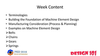
- 2. Week Content • Terminologies • Building the Foundation of Machine Element Design • Manufacturing Consideration (Process & Planning) • Examples on Machine Element Design Belts Chains Gears Springs
- 3. Terminologies • What is a Machine ? A device consisting of fixed and moving parts that modifies mechanical energy and transmits it in a more useful form
- 4. Terminologies What is an Element • All the machines are made up of elements or parts and units. • Each element is a separate part of the machine and it may have to be designed separately and in assembly. • Each element in turn can be a complete part or made up of several small pieces which are joined together by riveting, welding etc. • Several machine elements are assembled together to form what we call as complete machine.
- 5. Terminologies • What is (DFA) Design for Assembly is a process by which products are designed with ease of assembly in mind If a product contains fewer parts it will take less time to assemble
- 6. Building the Foundation of Machine Element Design • Types of Machines Mechanical Hydraulic Pneumatic Electrical Complex Systems Robotics
- 7. Building the Foundation of Machine Element Design • If we want to build up a machine what the main parameters to be consider ? Material Geometry Dimension But how to control this 3 factors Fourth Factor
- 8. The 4th Factor (Manufacturing) Historical Brief The word “manufacture” appeared in the 16th century and it is derived from the Latin “manu factus” which means “made by hand” . Manufacturing appeared at 5000-4000 BC, the earliest forms of manufacturing were invented by Sumerians around 3500 BC
- 9. Manufacturing Consideration • What is manufacturing? • A combination of processes applied on materials to convert it into products
- 10. Manufacturing Consideration • What is DFM? • DFM is abbreviation for Design For Manufacturing and it expresses a comprehensive approach to integrate the design with production methods. DFM includes the Manufacturing considerations
- 11. Manufacturing Considerations • was discussed from many points of view and classifications, no doubt that all these ones must be covered under the Manufacturing Plan. Here we will discuss the most common Considerations Cost Time Quality Safety Environment
- 12. The Role And Requirements Of Manufacturing Engineer • The main role is to carry out the design through planned manufacturing processes into the desired product so, the manufacturing engineer must have these abilities : designing new systems and processes for the introduction of new products or for the improvement of existing ones working with other engineers, such as chemical engineers, mechanical engineers, electrical engineers, to ensure all product and system requirements examining and tendering for new equipment to ensure the highest quality at the best price organizing plant start-up and shut-down schedules
- 13. Examples on Machine Element Design • This Elements were chosen based on this 3 criteria Famous and can be found in most of machines Have many types and shapes Don’t need high based knowledge to design and manipulate
- 14. Belts • The belts or ropes are used to transmit power from • one shaft to another by means of pulleys which rotate at the • same speed or at different speeds
- 15. Belts • The amount of power transmitted depends upon the following factors The velocity of the belt. The tension under which the belt is placed on the pulleys. The conditions under which the belt is used.
- 16. Belts Classification Belt DrivesType of Belt Light Drives Medium Drives Heavy Drives Flat Belt V-Belt Circular or Robe Belt
- 17. Materials of Pulleys Cast Iron Cast Steel Paper Pulleys
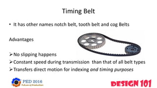
- 18. Timing Belt • It has other names notch belt, tooth belt and cog Belts Advantages No slipping happens Constant speed during transmission than that of all belt types Transfers direct motion for indexing and timing purposes
- 19. Material used for Belts Leather Belt Cotton BeltRubber Belt Balata belts
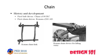
- 21. Chains • In order to avoid slipping, steel chains are used. The chains are made up of number of rigid links which are hinged together by pin joints in order to provide the necessary flexibility for wrapping round the driving and driven wheels.
- 22. Chain
- 23. Classification of Chains Hoisting and hauling Conveyor Chain Power Transmitting Block or bush chain Bush roller chain Silent chain
- 24. Power Transmitting Chains • These chains are used for transmission of power, when the distance between the centers of shafts is short. • These chains have provision for efficient lubrication.
- 25. Power Transmitting Chains • The power transmitting chains are of the following three types. 1. Block or bush chain 2. Bush roller chain 3. Silent chain
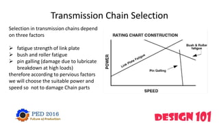
- 26. Transmission Chain Selection Selection in transmission chains depend on three factors fatigue strength of link plate bush and roller fatigue pin galling (damage due to lubricate breakdown at high loads) therefore according to pervious factors we will choose the suitable power and speed so not to damage Chain parts
- 27. Chain Failures
- 28. Chain Failures
- 29. Chain Failures
- 30. Gears The effect of slipping is to reduce the velocity ratio of the system In precision machines, in which a definite velocity ratio is of importance (as in watch mechanism), the only positive drive is by gears or toothed wheels. A gear drive is also provided, when the distance between the driver and the follower is very small.
- 31. Advantages and Disadvantages of Gear Drives Advantages • 1. It transmits exact velocity ratio. • 2. It may be used to transmit large power. • 3. It may be used for small center distances of shafts. • 4. It has high efficiency. • 5. It has reliable service.
- 32. Advantages and Disadvantages of Gear Drives Disadvantages 1. Since the manufacture of gears require special tools and equipment, therefore it is costlier than other drives. 2. The error in cutting teeth may cause vibrations and noise during operation. 3. It requires suitable lubricant and reliable method of applying it, for the proper operation of gear drives.
- 33. Gear Material The main characteristics considered in the design of gears are: • surface fatigue limit (Ssf). • root bending fatigue limit (Sbf). • wear resistance of tooth’s flank. • Machinability.
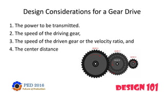
- 34. Design Considerations for a Gear Drive 1. The power to be transmitted. 2. The speed of the driving gear, 3. The speed of the driven gear or the velocity ratio, and 4. The center distance
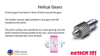
- 35. Helical Gears A helical gear has teeth in form of helix around the gear. The helixes may be right handed on one gear and left handed on the other. The pitch surfaces are cylindrical as in spur gearing, but the teeth instead of being parallel to the axis, wind around the cylinders helically like screw threads
- 36. Helical Gears Specifications Helical gear teeth "curved", teeth are cut at an angle Durable and ideal for high load applications Plastic, brass, steel, and aluminum are the materials generally used for manufacturing Helical gears operate with less noise and vibration than spur gears, and at any given time their load is distributed over several teeth, resulting in less wear.
- 37. Helical Gears Standards The Catalog Number for KHK stock gears is based on the simple formula listed below Caution in Selecting the Mating Gears. Right hand and left hand helical gears mate as a set.
- 39. Springs A spring is a resilient member capable of providing large elastic deformation. A spring is basically defined as an elastic body whose function is to distort when loaded and to recover its original shape when the load is removed. Mechanical springs are used in machines and other applications mainly To exert force To provide flexibility (Control of motion) To store or absorb energy. To measure forces
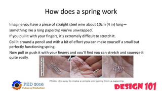
- 40. How does a spring work Imagine you have a piece of straight steel wire about 10cm (4 in) long— something like a long paperclip you've unwrapped. If you pull it with your fingers, it's extremely difficult to stretch it. Coil it around a pencil and with a bit of effort you can make yourself a small but perfectly functioning spring. Now pull or push it with your fingers and you'll find you can stretch and squeeze it quite easily.
- 41. Springs are great for storing or absorbing energy . When you use a pushing or pulling force to stretch a spring, you're using a force over a distance so, in physics terms, you're doing work and using energy. The tighter the spring, the harder it is to deform, the more work you have to do, and the more energy you need
- 42. Types of springs wire springs flat springs Special shaped springs
- 43. Spring manufacturing processes If springs are of very small diameter and the wire diameter is also small then the springs are normally manufactured by a cold drawn process through a mangle However, for very large springs having also large coil diameter and wire diameter one has to go for manufacture by hot processes. First one has to heat the wire and then use a proper mangle to wind the coils
- 44. Failure in springs Relaxation Corrosion Buckling Occurs when a spring is held at load or cycled under load. (Cyclic fatigue load). The absence of Coating Compression springs with a free length more than 4 times the mean coil diameter may buckle when compressed.
- 46. Machine Element Selection • Now we know many transmitting elements how we choose between them
- 47. Thank You