Closing the Design Cycle Loop with Executable Requirements and OSLC - IBM Internet of Things 2016
•
1 like•366 views

Motivation: Systems Engineering and Modeling and Simulation need to converge Open Standards we build on: Modelica, FMI, OSLC, SySML An Ideal Process to Integrate Systems Engineering with Model Based Design Continuous Integration to Close the Loop for Rapid Design Iterations First Steps to Automate Requirements Formalization Call to Action
Report
Share


Closing the Design Cycle Loop with Executable Requirements and OSLC - IBM Internet of Things 2016
- 1. 2016-11-23 1 CLOSING THE DESIGN CYCLE LOOP WITH EXECUTABLE REQUIREMENTS AND OSLC Hubertus Tummescheit, Modelon Bob Sherman, Procter & Gamble Juan Llorens, The Reuse Company Continuous Engineering for the Internet of Things Summit 2016
- 2. AGENDA • Motivation: Systems Engineering and Modeling and Simulation need to converge • Open Standards we build on: Modelica, FMI, OSLC, SySML • An Ideal Process to Integrate Systems Engineering with Model Based Design • Continuous Integration to Close the Loop for Rapid Design Iterations • First Steps to Automate Requirements Formalization • Call to Action
- 3. 23 November 2016 SYSTEMS ENGINEERING AND MODEL BASED DESIGN Two worlds that need to converge
- 4. Simulation-in-the-loop along the Design Flow of the Systems Engineering V Component Design Module Design Requirements & Performance Targets Finished Product Component Verification Module Integration & Verification System Integration & Validation System Design Modeling & Simulation IN THE V-MODEL is necessary Today But SE tools and Simulation tools Typically don’t Work together Many industries do this all the time, but the tools are not integrated! Systematically Building-up space of potential solutions1 Modelling and simulating potential solutions 2 Verifying against requirements and identifying the „best“ solution 3 Definition of top-level requirements and KPI derivation 0
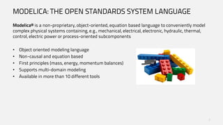
- 5. MODELICA: THE OPEN STANDARDS SYSTEM LANGUAGE Modelica® is a non-proprietary, object-oriented, equation based language to conveniently model complex physical systems containing, e.g., mechanical, electrical, electronic, hydraulic, thermal, control, electric power or process-oriented subcomponents • Object oriented modeling language • Non-causal and equation based • First principles (mass, energy, momentum balances) • Supports multi-domain modeling • Available in more than 10 different tools 5
- 6. FMI IN A NUTSHELL • What is FMI? an application programming interface and its semantics an xml schema that describes the model structure and capabilities the structure of a zip file that is used to package the model, its resources and documentation. • > 90 tools support FMI in 10 different categories. Supported by >90 tools: • 0/1-D ODE Simulators • Multibody Simulators • HIL Simulators /SIL tool chains • Scientific computation tools • Data analysis tools • Co-simulation backplanes • Software development tools • Systems engineering tools • Process integration and optimization tools • SDKs
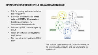
- 7. OPEN SERVICES FOR LIFECYCLE COLLABORATION (OSLC) • OSLC = reusing web standards for tool integration • Based on Web standards linked data and RESTful Web services • Create specifications for interactions between tools • Initiated by IBM, now managed by OASIS • Focus on software-and systems engineering • Not much traction (yet) with M&S tools 2016-11-23 7 We built an open-source OSLC-to-FMI connector to link simulation results and parameters to life cycle tools
- 8. AN IDEAL PROCESS TO INTEGRATE SYSTEMS ENGINEERING WITH MODEL BASED DESIGN 23 November 2016 8
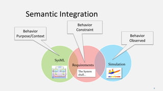
- 9. Semantic Integration 9 SysML SimulationRequirements Behavior ConstraintBehavior Purpose/Context Behavior Observed The System shall...
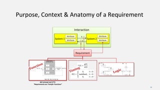
- 10. Purpose, Context & Anatomy of a Requirement 10 Interaction System 1 System 2 Requirement Attribute Attribute Attribute Attribute Bill Schindel (of ICTT): “Requirements are Transfer Functions” x y
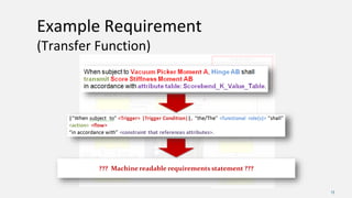
- 13. Example Requirement (Transfer Function) 13 ??? Machine readable requirements statement ???
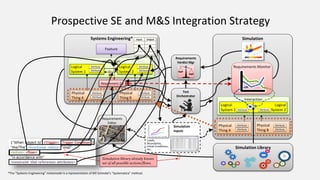
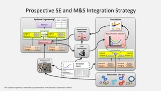
- 14. Simulation Prospective SE and M&S Integration Strategy *The “Systems Engineering” metamodel is a representation of Bill Schindel’s “Systematica” method. Simulation Library Systems Engineering* Interaction Logical System 1 Logical System 2 Requirement 2.1 Feature Physical Thing A Physical Thing B Attribute Attribute Attribute Attribute Attribute Attribute Attribute Attribute Interaction Physical Thing B Attribute Physical Thing A Attribute Attribute Attribute Logical System 1 Logical System 2 Requirements Verdict Mgr Requirements Monitor Requirements Editor Test Orchestrator Simulation Inputs Loads, Boundaries, Initial Conditions, etc. Attribute Attribute Requirement 2.1 Simulation library already knows set of all possible actions/flows.
- 15. Simulation Prospective SE and M&S Integration Strategy *The “Systems Engineering” metamodel is a representation of Bill Schindel’s “Systematica” method. Simulation Library Systems Engineering* Interaction Logical System 1 Logical System 2 Requirement 2.1 Feature Physical Thing A Physical Thing B Attribute Attribute Attribute Attribute Attribute Attribute Attribute Attribute Interaction Physical Thing B Attribute Physical Thing A Attribute Attribute Attribute Logical System 1 Logical System 2 Requirements Verdict Mgr Requirements Monitor Requirements Editor Test Orchestrator Simulation Inputs Loads, Boundaries, Initial Conditions, etc. Attribute Attribute Requirement 2.1
- 16. Implementation Space Functional Needs Space Prospective Mapping of Functional Architecture to Tool Suppliers Simulation Library Systems Engineering* System of Systems Logical System 1 Logical System 2 Requirement Feature Physical Thing A Physical Thing B Simulation LS Attribute LS Attribute LS Attribute LS Attribute LS Attribute LS Attribute LS Attribute LS Attribute Interaction Physical Thing B LS Attribute Physical Thing A LS Attribute LS Attribute LS Attribute Logical System 1 Logical System 2 Requirements Verdict Mgr Requirements Monitor Requirements Editor Test Orchestrator Test Orchestration Tool (InterCAX) Simulation Tool Systems Modeling Tool (IBM) Requirement Authoring Tool (Re-Use) Logical Modeling Tool (IBM) Standard Standard Standard Requirement Monitor Tool (Modelon) Requirement Verdicts Tool (???)
- 17. EXECUTABLE REQUIREMENTS Continuous feedback on compliance of requirements
- 18. Translate to Executable s IN-THE-LOOP REQUIREMENTS VERIFICATION Connect SE to MBD: Stakeholder Requirements Design Requirements All Pass? Test Cases Requirements Monitors Verifier Models Batch Execution Result Report Done Modify: • Reqs • System • Model Virtual SystemReal System Executable EnvironmentYes Requirements Manager No These exercise the system dynamics. Combining a test case with one or more monitors allows requirements to be verified.The complete set of executable verifier models can be tested automatically. Complete Coverage? When requirements are not met, modifications can be made to the system, model or even the requirements. These are the executable checks to verify the requirements are met. Specifying the requirements in a standard way, e.g. LTL, opens the possibility to automatically generate the executable monitors. The requirements manager should be able to verify that all requirements will be tested by the set of verifier models.The report shows a summary overview of the pass/fail results. Formalized Requirements These are low-level and testable. When possible also specified in a formal, open standard language.
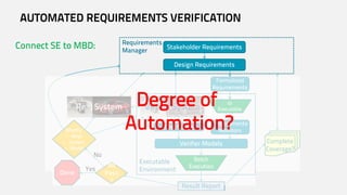
- 19. Translate to Executable s AUTOMATED REQUIREMENTS VERIFICATION Stakeholder Requirements Design Requirements All Pass ? Test Cases Requirements Monitors Verifier Models Batch Execution Result Report Done Modify: • Reqs • System • Model Virtual SystemReal System Executable EnvironmentYes Requirements Manager No Complete Coverage? Formalized Requirements Degree of Automation? Connect SE to MBD:
- 20. Automate Analysis & Deploy to team! AUTOMATED REQUIREMENTS VERIFICATION • Systems Engineering centric FMI-based workflow example: automated requirements verification for hardware and software requirements Requirements Formalized requirements Executable model of requirements (e.g. FMU) Physical plant Model of plant Deployable model of plant (FMU) Software spec Software model or prototype Deployable model of software (FMU) Development of a customized workflow to allow rapid iterations of plant & software configuration Operations Model of operations Model of operations / loads
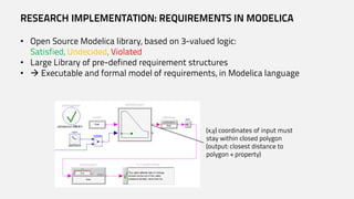
- 21. RESEARCH IMPLEMENTATION: REQUIREMENTS IN MODELICA • Open Source Modelica library, based on 3-valued logic: Satisfied, Undecided, Violated • Large Library of pre-defined requirement structures • Executable and formal model of requirements, in Modelica language (x,y) coordinates of input must stay within closed polygon (output: closest distance to polygon + property)
- 22. CONTINUOUS INTEGRATION OF REQUIREMENTS VERIFICATION Test Automation with Optimica Testing Tools (OTT)
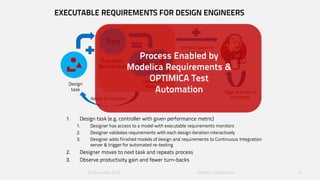
- 23. EXECUTABLE REQUIREMENTS FOR DESIGN ENGINEERS 1. Design task (e.g. controller with given performance metric) 1. Designer has access to a model with executable requirements monitors 2. Designer validates requirements with each design iteration interactively 3. Designer adds finished models of design and requirements to Continuous Integration server & trigger for automated re-testing 2. Designer moves to next task and repeats process 3. Observe productivity gain and fewer turn-backs 23 November 2016 Modelon Confidential 23 Design task Req Executable Requirements Validated Module Req Trigger & iterate on any changeRepeat for next task Add to CI server for continuous verificationProcess Enabled by Modelica Requirements & OPTIMICA Test Automation
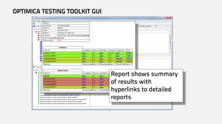
- 24. OPTIMICA TESTING TOOLKIT • Key features Modelica and FMI cross testing & execution platform Flexible test authoring, with GUI & scripts Simulation-specific automated validation Automated test execution and reporting • Architecture Core • Command line tool for running & automating tests • Integrated with Jenkins GUI • Tool for creating, updating and running tests • Reviewing and updating results
- 25. OPTIMICA TESTING TOOLKIT GUI Report shows summary of results with hyperlinks to detailed reports
- 26. TRANSFORMING NATURAL LANGUAGE TO A FORMAL REPRESENTATION Closing the gaps
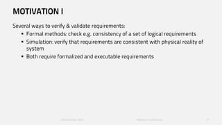
- 27. MOTIVATION I Several ways to verify & validate requirements: Formal methods: check e.g. consistency of a set of logical requirements Simulation: verify that requirements are consistent with physical reality of system Both require formalized and executable requirements 23 November 2016 Modelon Confidential 27
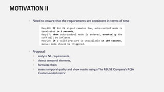
- 28. Need to ensure that the requirements are consistent in terms of time Proposal: analyze NL requirements, detect temporal elements, formalize them assess temporal quality and show results using aThe REUSE Company’s RQA Custom-coded metric MOTIVATION II
- 29. Method
- 30. Automatic Translation from Natural Language to Formal representation Method NL Requirement Conceptual graph representationRequirements Pattern Matching Formalized output Transformation Formal representation
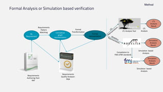
- 31. Formal Analysis or Simulation based verification Method NL Requirement Requirements Pattern Matching Formal Transformation LTL Analysis Result LTL Analysis Requirements Quality Analyzer: RQA Requirements Authoring Tool: RAT LTL Analysis Tool Conceptual graph representation Formal representation Simulation based Analysis Simulation Analysis Result Simulation based Analysis Simulation Analysis Result Compilation to FMU (FMI standard)
- 32. Create a Metric for LTL consistency: Custom Code in RQA RAT Overview
- 33. Example
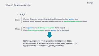
- 34. Shared Resource Arbiter SRA_2 When the flying engine activates, the propeller shall be canceled until the ignition starts When the aircraft departures, the wheels shall be closed until the electrical power system activates When ignition starts, electrical power system shall be stopped When electrical power system activates, ignition shall be deactivated G((flying_engine=1) X((propeller=0)U(ignition=1))); G((aircraft=1) X((wheel=0)U(electrical_power_system=1))); G((ignition=0) + (electrical_power_system=0)); Example Client Mutex
- 35. Shared Resource Arbiter SRA_3 When the flying engine activates, the propeller shall be canceled until the ignition starts When the aircraft launches, the wheels shall be closed until the electrical power system activates When the navigation system starts, the control mode shall be stopped until the gearshift enables When ignition starts, electrical power system and gearshift shall be stopped When electrical power system activates, ignition and gearshift shall be deactivated When gearshift begins, ignition and electrical power system shall be terminated G((flying_engine=1) X((propeller=0)U(ignition=1))); G((aircraft=1) X((wheel=0)U(electrical_power_system=1))); G((navigation_system=1) X((auto_control_mode=0)U(gearshift=1))); G(((electrical_power_system=0) * (gearshift=0)) + ((ignition=0) * (gearshift=0)) + ((ignition=0) * (electrical_power_system=0))); Example Client Mutex
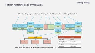
- 37. Pattern matching and Formalization Ontology Building When the flying engine activates, the propeller shall be canceled until the ignition starts «Time» «System» «Start» ADVERB NOUN «Stop» VERB VERB or «Start» «Stop» VERB VERB or Shall «System» NOUN VERB Until «System» «Start» NOUN «Stop» VERB VERB or Flying Engine Propeller «Stop» Ignition Attribute Value ReqType Client Flying Engine Activated Propeller Deactivated Ignition Activated G((flying_engine=1) X((propeller=0)U(ignition=1)));
- 38. RAT overview
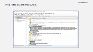
- 39. Plug-in for IBM rational DOORS RAT Overview
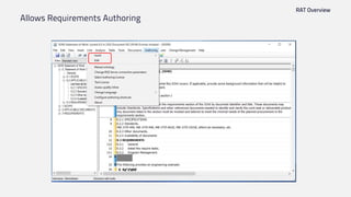
- 40. Allows Requirements Authoring RAT Overview
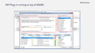
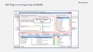
- 41. RAT Plug-in running on top of DOORS RAT Overview
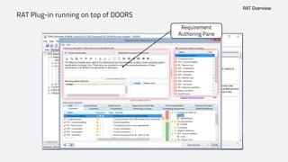
- 42. RAT Plug-in running on top of DOORS RAT Overview Requirement Authoring Pane
- 43. RAT Plug-in running on top of DOORS RAT Overview Quality Pane: Correctness
- 44. RAT Plug-in running on top of DOORS RAT Overview Decision Support Pane
- 45. RAT Plug-in running on top of DOORS RAT Overview Correctness Quality Value Structural Quality Value
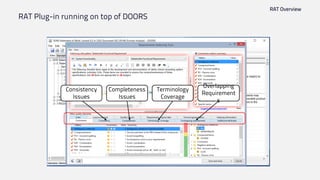
- 46. RAT Plug-in running on top of DOORS RAT Overview Overlapping Requirement s Terminology Coverage Completeness Issues Consistency Issues
- 47. WHERE DOES THIS LEAVE US OVER ALL? We have a vision of an integrated process and tool landscape to bring together Systems Engineering and Model Based Design A few good things can be done today: The RAT allows to write high quality requirements, integrated into requirements management We can use Modelica to make requirements executable We can give the requirements to design engineers and enable automated requirements verification with Optimica Testing Tools We can transform natural language requirements to a formal representation for formal or simulation based verification There are still many missing links to fill the gaps!
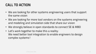
- 48. CALL TO ACTION • We are looking for other systems engineering users that support the same vision • We are looking for more tool vendors on the systems engineering and modeling and simulation side that share our vision • We strongly believe in open standards to connect SE & MBD • Let’s work together to make this a reality: We need better tool integration to enable engineers to design complex systems! 23 November 2016 48
Editor's Notes
- Architectures: unique to Modelica: Add FEM/CAD as fidelity level
- We discussed the Modelica for feature design and ROM for functional fidelity design, next is the Interfaces for multiple kinds simulation design including X-in-the-loop interfaces, and also dynamics integration, steady-state simulation, optimization, robust design,… The key is FMI. What is FMI?... There are currently 77 tools claimed to support FMI. And we can classify them into 7 categories. We see that FMI is actually not restricted within X-in-the-loop interface but has also affect to the interoperability at feature design and fidelity design.
- To 2: it really matters that FMI integrates EXISTING tools, leveraging investments already made.