


Usm unit 2
- 1. D.Palani Kumar, Assistant Prof. / Mech. Engg., Kamaraj College of Engg. & Tech. Virudhunagar.
- 2. Introduction USM is a mechanical type NTMP. It is employed to machine materials ( both conductive and non-conductive )hardness usually greater than 40 RC. The word ultrasonic describes a vibratory wave having frequency larger than upper frequency limit of human ear(usually greater than 20kHz). High velocity longitudinal waves are used in USM because they can easily propagate in solids, liquids and gases.
- 4. Main Components Slurry delivery and return system Feed mechanism to provide a downward feed force on the tool during machining The transducer, which generates the ultrasonic vibration The horn or concentrator, which mechanically amplifies the vibration to the required amplitude of 15 – 50μm and accommodates the tool at its tip . The ultrasonic vibrations are produced by the transducer.
- 6. Ultrasonic Transducer A device which converts any form of energy into ultrasonic waves called as Ultrasonic Transducer. In USM, it converts high frequency electrical signal into high frequency linear mechanical motion called as Vibration. The transducer for USM works on the following principle Piezoelectric effect Magnetostrictive effect Electrostrictive effect
- 7. Piezoelectric transducer These transducers generate a small electric current when they are compressed. Also when the electric current is passed though crystal it expands. When the current is removed, crystal attains its original size and shape. Such transducers are available up to 900 Watts. Piezo electric crystals have high conversion efficiency of 95%.
- 8. These also changes its length when subjected to strong magnetic field. These transducer are made of nickel, nickel alloy sheets. Their conversion efficiency is about 20-30%. Such transducers are available up to 2000 Watts. The maximum change in length can be achieved is about 25 microns. The most commonly used transducer in the USM.
- 10. Electrostrictive effect Electrostriction is a property of all dielectric materials, and is caused by the presence of randomly aligned electrical domains within the material. When an electric field is applied to the dielectric, the opposite sides of the domains become differently charged and attract each other, reducing material thickness in the direction of the applied field (and increasing thickness in the orthogonal directions characterized by Poisson's ratio). The resulting strain (ratio of deformation to the original dimension) is proportional to the square of the polarization. Reversal of the electric field does not reverse the direction of the deformation.
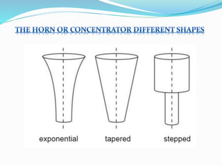
- 11. Horn or Concentrator The horn or concentrator is a wave-guide, which amplifies and concentrates the vibration to the tool from the transducer. The horn or concentrator can be of different shape like Tapered or conical Exponential Stepped Machining of tapered or stepped horn is much easier as compared to the exponential one.
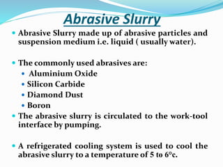
- 13. Abrasive Slurry Abrasive Slurry made up of abrasive particles and suspension medium i.e. liquid ( usually water). The commonly used abrasives are: Aluminium Oxide Silicon Carbide Diamond Dust Boron The abrasive slurry is circulated to the work-tool interface by pumping. A refrigerated cooling system is used to cool the abrasive slurry to a temperature of 5 to 6°c.
- 14. CONT…….. The size of the abrasive varies between 200 and 2000 grit. Coarse grades are good for roughing, where finer grades, say 1000 frit, are used for finishing. Fresh abrasives cut better and the slurry therefore be replaced periodically.
- 15. Slurry Media Properties The liquid to produce abrasive slurry should have the following properties: Good Wetting characteristics Low viscosity High thermal conductivity Anti corrosive property Approximately having equal density with abrasive Low cost
- 16. Mechanics of Cutting Material removal primarily occurs due to the indentation of the hard abrasive grits on the brittle work material. As the tool vibrates, it leads to indentation of the abrasive grits. During indentation, due to Hertzian contact stresses, cracks would develop just below the contact site, then as indentation progresses the cracks would propagate due to increase in stress and ultimately lead to brittle fracture of the work material under each individual interaction site between the abrasive grits and the work-piece. .
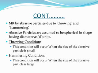
- 17. CONT………. MR by abrasive particles due to ‘throwing’ and ‘‘hammering’. Abrasive Particles are assumed to be spherical in shape having diameter as ‘d’ units. Throwing Condition: This condition will occur When the size of the abrasive particle is small Hammering Condition: This condition will occur When the size of the abrasive particle is large
- 18. CONT…… In both cases, a particle after hitting the work surface generates a crater with depth δw . The abrasive particles are characterized by the average grit diameter, dg. It is further assumed that the local spherical bulges have a uniform diameter, db and which is related to the grit diameter by db = μdg 2. Thus an abrasive is characterized by μ and dg.
- 19. CONT…
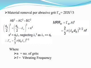
- 20. Material removal per abrasive grit Гw= 2ΠX3/3 Where n = no. of grits f = Vibrating Frequency
- 22. Where F = Feed Force n = no. of abrasive grits C = Volume Concentration of abrasive grit A = Contact area of the tool
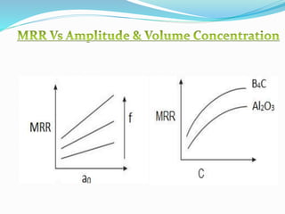
- 24. Parameters affecting the MRR Amplitude of vibration (ao) – 15 – 50 μm Frequency of vibration (f) – 19 – 25 kHz Feed force (F) – related to tool dimensions Feed pressure (p) Abrasive size – 15 μm – 150 μm Abrasive material – Al2O3 - SiC - B4C - Boronsilicarbide - Diamond Flow strength of work material Flow strength of the tool material Contact area of the tool – A Volume concentration of abrasive in water slurry – C
- 26. MRR Vs Feed Force MRR α F 3/4
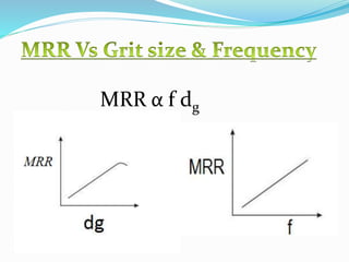
- 27. MRR α f dg
- 29. Case Study
- 30. Introduction Titanium and its alloys are alternative for many engineering applications due to their superior properties such as chemical inertness, high strength and stiffness at elevated temperatures, high strength to weight ratio, corrosion resistance, and oxidation resistance. Titanium and its alloys are poor thermal conductors. As a result, the heat generated when machining titanium cannot dissipate quickly; rather, most of the heat is concentrated on the cutting edge and tool face. The surface finish achieved by a single machining process (no finishing operations) is poor. Therefore, there is a crucial need for reliable and cost- effective machining processes for titanium and its alloys.
- 31. CONT……… Nontraditional machining processes such as EDM and LBM have been applied to the machining of titanium and its alloys in recent times, but even these processes have their own limitations; the most prominent are the surface finish and dimensional inaccuracies besides their undesirable effects on the machined surface such as heat affected zone, thermal stresses, etc. Ultrasonic Machining (USM) could be another alternative machining process that can be applied commercially to the machining of titanium; as this process is known to be free from all these adverse effects on the machined component, and the repeated impacts of abrasive grains on the work surface lead to a favorable compressive surface stress thereby improving the fatigue life of titanium components along with the surface integrity.
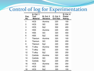
- 32. Materials Pure titanium (ASTM grade-i) has been used as the work material . Five type of tools made of high carbon steel, high speed steel, cemented carbide, titanium (ASTM grade-i) and titanium alloy (ASTM grade-v) with straight cylindrical geometry (diameter 8 mm) are used. All the tools except cemented carbide were made as one piece unit and attached to the horn by tightening the threaded portion of the tool with the horn. Three types of abrasive materials were used: silicon carbide, aluminum oxide and boron carbide. Three different grit sizes were selected for each abrasive material: 220, 320 and 500
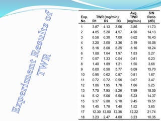
- 33. Experiment To measure the tool wear rate (TWR), the time taken for drilling each hole was recorded using stop watch. The tool was weighed before and after drilling each hole using electronic balance. The weight loss for drilling each hole was thus recorded. TWR was calculated by taking the ratio of weight loss of tool per hole to the product of drilling time per hole. The surface roughness of the machined surface was evaluated by using Perthometer. Three observations were taken for each hole and were averaged to obtain the value of roughness.
- 35. Control of log for Experimentation
- 38. TWR Analysis It can be observed from figure that the tool material affects the rate of wear of the tool very significantly. Moreover, the different tool materials used in the experimentation can be ranked in the order of increasing tool wear rate as Ti alloy, Titanium, HSS, HCS, Cemented carbide. The lowest tool wear has been recorded for titanium alloy (ASTM Grade –V). This can be attributed to its excellent combination of high fracture toughness and optimum hardness (42 RC) from the point of view of USM process. The use of a coarser grit size promotes the increase in tool wear rate further use of coarse abrasive grains results in stronger impacts on the tool surface and hence the rate of fracture increases.
- 39. It is clear from slide no. 37 that tool wear rate (TWR) is lowest at the fourth level of tool material parameter (A4), first level of abrasive material parameter (B1), third level of the grit size (C3) and also the first level of power rating (D1). It has also been observed that for a given tool material, TWR is maximum at that particular grit size-power level combination which corresponds to maximum MRR. In other words, TWR is maximum at the points of maximum MRR.
- 40. Surface Roughness The lowest tool wear has been recorded for titanium alloy (ASTM Grade –V). This can be explained on the basis of the Machining rate obtained with different tool materials. In USM process, as the machining rate increases, the surface quality deteriorates, the reason being formation of larger micro cavities at the time of machining. The larger micro cavities give rise to rougher surface. As the use of titanium alloy tool involves least machining rate, it also promotes the reduction in surface roughness, thereby generating better surface finish.
- 41. APPLICATIONS Used for machining hard and brittle metallic alloys, semiconductors, glass, ceramics, carbides etc. Used for machining round, square, irregular shaped holes and surface impressions. Machining, wire drawing, punching or small blanking dies.
- 42. Advantages It can be used machine hard, brittle, fragile and non conductive material No heat is generated in work, therefore no significant changes in physical structure of work material Non-metal (because of the poor electrical conductivity) that cannot be machined by EDM and ECM can very well be machined by USM. It is burr less and distortion less processes. It can be adopted in conjunction with other new technologies like EDM,ECG,ECM.
- 43. Disadvantages Low Metal removal rate It is difficult to drill deep holes, as slurry movement is restricted. Tool wear rate is high due to abrasive particles. Tools made from brass, tungsten carbide, MS or tool steel will wear from the action of abrasive grit with a ratio that ranges from 1:1 to 200:1 USM can be used only when the hardness of work is more than 45 HRC.
- 44. References An experimental study on ultrasonic machining of pure titanium using designed experiments by Jatinder Kumar and J. S. Khamba Non-Conventional Machining Methods ( NTMM), NPTEL Material