IRJET- Heat Exchanger Analysis and Method to Improve its Effectiveness
•
0 likes•32 views

This document discusses heat exchanger analysis and methods to improve heat exchanger effectiveness. It begins with an abstract that outlines analyzing heat exchangers using the log-mean temperature difference and number of transfer unit methods. It then discusses varying the mass flow rates of the hot and cold fluids in a counter flow heat exchanger and analyzing the effects on parameters like effectiveness, heat transfer coefficient, and capacity ratio. The key findings are that decreasing the mass flow rates of both the hot and cold fluids leads to increased heat exchanger effectiveness.
Report
Share
IRJET- Heat Exchanger Analysis and Method to Improve its Effectiveness
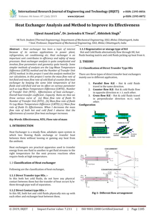
- 1. International Research Journal of Engineering and Technology (IRJET) e-ISSN: 2395-0056 Volume: 06 Issue: 07 | July 2019 www.irjet.net p-ISSN: 2395-0072 © 2019, IRJET | Impact Factor value: 7.211 | ISO 9001:2008 Certified Journal | Page 1185 Heat Exchanger Analysis and Method to Improve its Effectiveness Ujjwal Anand Jain 1 , Dr. Jeetendra K Tiwari 2 , Abhishek Singh 3 1M.Tech. Student (Thermal Engineering), Department of Mechanical Engineering, SSGI, Bhilai, Chhattisgarh, India 2,3Asst. Professor, Department of Mechanical Engineering, SSGI, Bhilai, Chhattisgarh, India ----------------------------------------------------------------------------***----------------------------------------------------------------------------- Abstract - Heat exchanger has been a topic of interest because of its various applications in power plant, refrigeration, air conditioning etc. Heat exchanger is an important unit contributes to efficiency and safety of many processes. Heat exchanger analysis is quite complicated and involves flow parameters and geometry quite heavily. Some simpler methods of analysis are the Log-Mean Temperature Difference (LMTD) method and the Number of Transfer Unit (NTU) method. In this project I used this analysis method for our calculation, in this project I varies the mass flow rate of hot fluid and mass flow rate of cold fluid of counter flow heat exchanger by keeping the same inlet temperature of hot fluids and cold fluid and see its effect on various parameter such as Log-Mean Temperature Difference (LMTD) , Number of Transfer Unit (NTU) , Effectiveness of heat exchanger , Overall heat transfer coefficient , Capacity Ratio etc then we Draw various curve of (a) Mass flow rate of fluids Vs Number of Transfer Unit (NTU) , (b) Mass flow rate of fluids Vs Log-Mean Temperature Difference (LMTD) (c) Mass flow rate of fluids Vs Effectiveness. When I decreases the mass flow rate of both hot and cold fluid I observe that the effectiveness of counter flow heat exchanger increases. Key Words: Effectiveness, NTU, Flow rate of mass 1. INTRODUCTION Heat Exchanger is a steady flow, adiabatic open system in which two flowing fluids exchange or transfer heat between them without loosing or gaining any heat from the ambient. Heat exchangers are practical apparatus used to transfer energy from one fluid to another to get fluid streams to the right temperature for the next process reactions often require feeds at high temperature. 1.1 Classification of Heat exchanger Following are the classification of heat exchanger, 1.1.1 Direct Transfer type HEs. :- In this both hot cold fluids, do not have any physical contact between them but the transfer of heat occurs b/w them through pipe wall of separation. 1.1.2 Direct Contact type HEs. :- In this HE, both hot and cold fluids physically mix up with each other and exchanger heat between them. 1.1.3 Regenerative or storage type of H.E Hot and Cold fluids alternatively flow through HE, hot fluids heating matrix and cold fluids picking up heat from it. 2. THEORY 2.1 Classification of Direct Transfer Type HEs There are three types of direct transfer heat exchangers mainly use in different application, 1. Parallel flow H.E - Hot & cold fluids travel in the same direction. 2. Counter flow H.E- Hot & cold fluids flow in opposite direction w. r. t. each other. 3. Cross flow H.E - Hot & cold fluids travel in perpendicular direction w.r.t. each other. Configuration Fig-1- Different flow arrangement
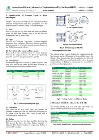
- 2. International Research Journal of Engineering and Technology (IRJET) e-ISSN: 2395-0056 Volume: 06 Issue: 07 | July 2019 www.irjet.net p-ISSN: 2395-0072 © 2019, IRJET | Impact Factor value: 7.211 | ISO 9001:2008 Certified Journal | Page 1186 3. Specification of Various Parts of Heat Exchanger- The flow rate of mass of both hot and cold streams, their terminal temperatures and fluid properties are the primary inputs of thermal design of heat exchangers. 3.1 Shell Shell is the pot for the fluid and the tubes are placed inside the shell. Shell diameter must be elected in such a way to give a seal fit of the tubes. 3.2 Tube Tube OD of 0.75 inc and 1 inc are very common to design a compact heat exchanger. The most pleasant condition for heat transfer is to have the utmost number of tubes in the shell to increase turbulence. 3.3 Tube pitch, tube-layout and tube-count Tube pitch is the smallest centre to centre distance between the adjacent tubes. The tubes are generally placed in square or triangular patterns (pitch). 3.4 Tube passes The number of passes is chosen to get the required tube side fluid velocity to obtain greater heat transfer co- efficient and also to reduce scale formation. Fig 2- Dimensions and pitch type 3.5 Tube sheet The tubes are set with tube sheet that creates the blockade between the tube and shell fluids. The tubes can be joined with the tube sheet using ferrule and a malleable metal packing ring. 3.6 Baffles Baffles are used to raise the fluid speed by diverting the flow across the tubes to obtain higher transfer co- efficient. The distance between neighboring baffles is called baffle-spacing. Fig 3- Different types of baffles 3.7 Fouling Considerations The majority of the process fluids in the exchanger foul the heat transfer surface. The material deposited decreases the effective heat transfer rate due to relatively low thermal conductivity. Therefore, net heat transfer rate with clean surface should be higher to compensate the reduction in performance during operation. Fig 4 – Fouling Factors of different fluids 3.8 Selection of fluids for tube and the shell side The routing of the shell side and tube side fluids has significant effects on the heat exchanger design Fig5- General guidelines for positioning the fluids
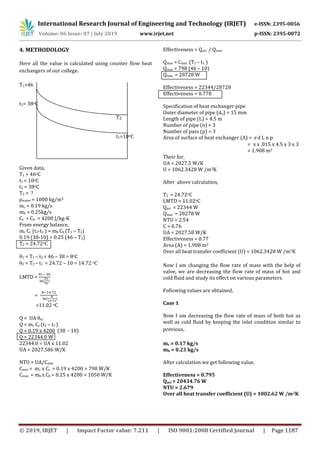
- 3. International Research Journal of Engineering and Technology (IRJET) e-ISSN: 2395-0056 Volume: 06 Issue: 07 | July 2019 www.irjet.net p-ISSN: 2395-0072 © 2019, IRJET | Impact Factor value: 7.211 | ISO 9001:2008 Certified Journal | Page 1187 4. METHODOLOGY Here all the value is calculated using counter flow heat exchangers of our college. T1=46 t2= 38oC T2 t1=10oC Given data, T1 = 46oC t1 = 10oC t2 = 38oC T2 = ? ρwater = 1000 kg/m3 mc = 0.19 kg/s mh = 0.25kg/s Cc = Ch = 4200 J/kg-K From energy balance, mc Cc (t2-t1 ) = mh Ch (T1 – T2) 0.19 (38-10) = 0.25 (46 – T2) T2 = 24.72oC 1 = T1 – t2 = 46 – 38 = 8oC 2 = T2 – t1 = 24.72 – 10 = 14.72 oC LMTD = = =11.02 oC Q = UA m Q = mc Cc (t2 – t1 ) Q = 0.19 x 4200 (38 - 10) Q = 22344.0 W 22344.0 = UA x 11.02 UA = 2027.586 W/K NTU = UA/Cmin Cmin = mc x Cc = 0.19 x 4200 = 798 W/K Cmax = mh x Ch = 0.25 x 4200 = 1050 W/K Effectiveness = Qact / Qmax Qmax = Cmin (T1 – t1 ) Qmax = 798 (46 – 10) Qmax = 28728 W Effectiveness = 22344/28728 Effectiveness = 0.778 Specification of heat exchanger pipe Outer diameter of pipe (do) = 15 mm Length of pipe (L) = 4.5 m Number of pipe (n) = 3 Number of pass (p) = 3 Area of surface of heat exchanger (A) = d L n p = x .015 x 4.5 x 3 x 3 = 1.908 m2 Their for, UA = 2027.5 W/K U = 1062.3428 W /m2K After above calculation, T2 = 24.72oC LMTD = 11.02oC Qact = 22344 W Qmax = 28278 W NTU = 2.54 C = 0.76 UA = 2027.58 W/K Effectiveness = 0.77 Area (A) = 1.908 m2 Over all heat transfer coefficient (U) = 1062.3428 W /m2K Now I am changing the flow rate of mass with the help of valve, we are decreasing the flow rate of mass of hot and cold fluid and study its effect on various parameters. Following values are obtained, Case 1 Now I am decreasing the flow rate of mass of both hot as well as cold fluid by keeping the inlet condition similar to previous. mc = 0.17 kg/s mh = 0.23 kg/s After calculation we get following value, Effectiveness = 0.795 Qact = 20434.76 W NTU = 2.679 Over all heat transfer coefficient (U) = 1002.62 W /m2K
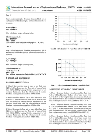
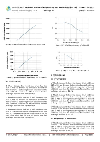
- 4. International Research Journal of Engineering and Technology (IRJET) e-ISSN: 2395-0056 Volume: 06 Issue: 07 | July 2019 www.irjet.net p-ISSN: 2395-0072 © 2019, IRJET | Impact Factor value: 7.211 | ISO 9001:2008 Certified Journal | Page 1188 Case 2 Now I am decreasing the flow rate of mass of both hot as well as cold fluid by keeping the inlet condition similar to previous. mc = 0.15 kg/s mh = 0.21 kg/s After calculation we get following value, Effectiveness = 0.81 Qact = 18370 W NTU = 2.856 Over all heat transfer coefficient (U) = 943 W /m2K Case 3 Now I am decreasing the flow rate of mass of both hot as well as cold fluid by keeping the inlet condition similar to previous. mc = 0.13 kg/s mh = 0.19 kg/s After calculation we get following value, Effectiveness = 0.82 Qact = 16117.92 W NTU = 2.92 Over all heat transfer coefficient (U) = 816.97 W /m2K 5. RESULT AND DISCUSSIONS 5.1 EFFECT ON EFFECTIVENESS 1. When I decrease flow rate of mass of hot fluid from 0.25 to 0.23 and decrease the flow rate of mass of cold from 0.19 to 0.17 by keeping the inlet temperature of hot and cold fluids same then the effectiveness of counter flow heat exchanger increases from 0.77 to 0.795. 2. When I decrease the flow rate of mass of hot fluid from 0.23 to 0.21 and decrease the flow rate of mass of cold from 0.17 to 0.15 by keeping the inlet temperature of hot and cold fluids same then the effectiveness of counter flow heat exchanger increases from 0.795 to 0.81. 3. When I decrease the flow rate of mass of hot fluid from 0.21 to 0.19 and decrease the flow rate of mass of cold from 0.15 to 0.13 by keeping the inlet temperature of hot and cold fluids same then the effectiveness of counter flow heat exchanger increases from 0.81 to 0.82. Chart 1 - Effectiveness Vs Mass flow rate of cold fluid Chart 2 - Effectiveness Vs Mass flow rate of hot fluid 5.2 EFFECT ON ACTUAL HEAT TRANSFER RATE 1. When I decrease the flow rate of mass of hot fluid from 0.25 to 0.23 and decrease the flow rate of mass of cold from 0.19 to 0.17 by keeping the inlet temperature of hot and cold fluids same then the heat transfer rate of counter flow heat exchanger decreases from 22344 W to 20434.76 W. 2. When I decrease the flow rate of mass of hot fluid from 0.23 to 0.21 and decrease the flow rate of mass of cold from 0.17 to 0.15 by keeping the inlet temperature of hot and cold fluids same then the heat transfer rate of counter flow heat exchanger decreases from 20434.76 W to 18370 W. 3. When I decrease the flow rate of mass of hot fluid from 0.21 to 0.19 and decrease the flow rate of mass of cold from 0.15 to 0.13 by keeping the inlet temperature of hot and cold fluids same then the heat transfer rate of counter flow heat exchanger decreases from 18370 W to 16117 W.
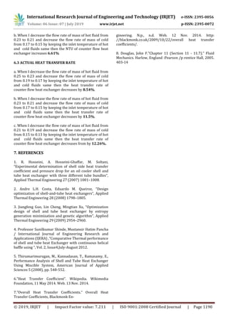
- 5. International Research Journal of Engineering and Technology (IRJET) e-ISSN: 2395-0056 Volume: 06 Issue: 07 | July 2019 www.irjet.net p-ISSN: 2395-0072 © 2019, IRJET | Impact Factor value: 7.211 | ISO 9001:2008 Certified Journal | Page 1189 Chart 3-Heat transfer rate Vs Mass flow rate of cold fluid Chart 4- Heat transfer rate Vs Mass flow rate of hot fluid 5.3 EFFECT ON NTU 1. When I decrease flow rate of mass of hot fluid from 0.25 to 0.23 and decrease the flow rate of mass of cold from 0.19 to 0.17 by keeping the inlet temperature of hot and cold fluids same then the NTU of counter flow heat exchanger increases from 2.541 to 2.679 2. When I decrease the flow rate of mass of hot fluid from 0.23 to 0.21 and decrease the flow rate of mass of cold from 0.17 to 0.15 by keeping the inlet temperature of hot and cold fluids same then the NTU of counter flow heat exchanger increases from 2.679 to 2.856. 3. When I decrease the flow rate of mass of hot fluid from 0.21 to 0.19 and decrease flow rate of mass of cold from 0.15 to 0.13 by keeping the inlet temperature of hot and cold fluids same then the NTU of counter flow heat exchanger increases from 2.856 to 2.92. Chart 5- NTU Vs Mass flow rate of cold fluid Chart 6- NTU Vs Mass flow rate of hot fluid 6. CONCLUSIONS 6.1 EFFECTIVENESS a. When I decrease the flow rate of mass of hot fluid from 0.25 to 0.23 and decrease the flow rate of mass of cold from 0.19 to 0.17 by keeping the inlet temperature of hot and cold fluids same then the effectiveness of counter flow heat exchanger increases by 3.24%. b. When I decrease the flow rate of mass of hot fluid from 0.23 to 0.21 and decrease the flow rate of mass of cold from 0.17 to 0.15 by keeping the inlet temperature of hot and cold fluids same then the effectiveness of counter flow heat exchanger increases by 1.88 %. c. When I decrease the flow rate of mass of hot fluid from 0.21 to 0.19 and decrease the flow rate of mass of cold from 0.15 to 0.13 by keeping the inlet temperature of hot and cold fluids same then the effectiveness of counter flow heat exchanger increases by 1.23%. 6.2 NTU (Number of transfer unit) a. When I decrease the flow rate of mass of hot fluid from 0.25 to 0.23 and decrease the flow rate of mass of cold from 0.19 to 0.17 by keeping the inlet temperature of hot and cold fluids same then the NTU of counter flow heat exchanger increases by 5.43%.
- 6. International Research Journal of Engineering and Technology (IRJET) e-ISSN: 2395-0056 Volume: 06 Issue: 07 | July 2019 www.irjet.net p-ISSN: 2395-0072 © 2019, IRJET | Impact Factor value: 7.211 | ISO 9001:2008 Certified Journal | Page 1190 b. When I decrease the flow rate of mass of hot fluid from 0.23 to 0.21 and decrease the flow rate of mass of cold from 0.17 to 0.15 by keeping the inlet temperature of hot and cold fluids same then the NTU of counter flow heat exchanger increases 6.61% 6.3 ACTUAL HEAT TRANSFER RATE a. When I decrease the flow rate of mass of hot fluid from 0.25 to 0.23 and decrease the flow rate of mass of cold from 0.19 to 0.17 by keeping the inlet temperature of hot and cold fluids same then the heat transfer rate of counter flow heat exchanger decreases by 8.54%. b. When I decrease the flow rate of mass of hot fluid from 0.23 to 0.21 and decrease the flow rate of mass of cold from 0.17 to 0.15 by keeping the inlet temperature of hot and cold fluids same then the heat transfer rate of counter flow heat exchanger decreases by 11.5%. c. When I decrease the flow rate of mass of hot fluid from 0.21 to 0.19 and decrease the flow rate of mass of cold from 0.15 to 0.13 by keeping the inlet temperature of hot and cold fluids same then the heat transfer rate of counter flow heat exchanger decreases from by 12.26%. 7. REFERENCES 1. R. Hosseini, A. Hosseini-Ghaffar, M. Soltani, “Experimental determination of shell side heat transfer coefficient and pressure drop for an oil cooler shell and tube heat exchanger with three different tube bundles”, Applied Thermal Engineering 27 (2007) 1001–1008. 2. Andre L.H. Costa, Eduardo M. Queiroz, “Design optimization of shell-and-tube heat exchangers”, Applied Thermal Engineering 28 (2008) 1798–1805. 3. Jiangfeng Guo, Lin Cheng, Mingtian Xu, “Optimization design of shell and tube heat exchanger by entropy generation minimization and genetic algorithm”, Applied Thermal Engineering 29 (2009) 2954–2960. 4. Professor Sunilkumar Shinde, Mustansir Hatim Pancha / International Journal of Engineering Research and Applications (IJERA) ,”Comparative Thermal performance of shell and tube heat Exchanger with continuous helical baffle using “, Vol. 2, Issue4,July-August 2012. 5. Thirumarimurugan, M., Kannadasan, T., Ramasamy, E., Performance Analysis of Shell and Tube Heat Exchanger Using Miscible System, American Journal of Applied Sciences 5 (2008), pp. 548-552. 6.”Heat Transfer Coefficient”. Wikipedia. Wikimedia Foundation, 11 May 2014. Web. 13 Nov. 2014. 7.”Overall Heat Transfer Coefficients.” Overall Heat Transfer Coefficients, Blackmonk En- gineering. N.p., n.d. Web. 12 Nov. 2014. http: //blackmonk.co.uk/2009/10/22/overall heat transfer coefficients/. 8. Douglas, John F.”Chapter 11 (Section 11 - 11.7).” Fluid Mechanics. Harlow, England :Pearson /p rentice Hall, 2005. 403-14